US2972466A - Discharge head - Google Patents
Discharge head Download PDFInfo
- Publication number
- US2972466A US2972466A US67727657A US2972466A US 2972466 A US2972466 A US 2972466A US 67727657 A US67727657 A US 67727657A US 2972466 A US2972466 A US 2972466A
- Authority
- US
- United States
- Prior art keywords
- passage
- valve member
- piston
- discharge head
- pressure
- Prior art date
- Legal status (The legal status is an assumption and is not a legal conclusion. Google has not performed a legal analysis and makes no representation as to the accuracy of the status listed.)
- Expired - Lifetime
Links
- 239000012530 fluid Substances 0.000 description 31
- 238000005192 partition Methods 0.000 description 16
- 230000001681 protective effect Effects 0.000 description 9
- 238000010276 construction Methods 0.000 description 7
- 230000004323 axial length Effects 0.000 description 5
- 238000007789 sealing Methods 0.000 description 4
- 239000003795 chemical substances by application Substances 0.000 description 3
- 238000009434 installation Methods 0.000 description 3
- CURLTUGMZLYLDI-UHFFFAOYSA-N Carbon dioxide Chemical compound O=C=O CURLTUGMZLYLDI-UHFFFAOYSA-N 0.000 description 2
- 230000006378 damage Effects 0.000 description 2
- 239000000463 material Substances 0.000 description 2
- 230000007246 mechanism Effects 0.000 description 2
- 238000013022 venting Methods 0.000 description 2
- 241001136792 Alle Species 0.000 description 1
- 206010012289 Dementia Diseases 0.000 description 1
- 208000027418 Wounds and injury Diseases 0.000 description 1
- 239000001569 carbon dioxide Substances 0.000 description 1
- 229910002092 carbon dioxide Inorganic materials 0.000 description 1
- 208000014674 injury Diseases 0.000 description 1
- 238000004519 manufacturing process Methods 0.000 description 1
- 230000002265 prevention Effects 0.000 description 1
- 229940101201 ringl Drugs 0.000 description 1
- 239000004404 sodium propyl p-hydroxybenzoate Substances 0.000 description 1
- 239000013589 supplement Substances 0.000 description 1
- XLYOFNOQVPJJNP-UHFFFAOYSA-N water Substances O XLYOFNOQVPJJNP-UHFFFAOYSA-N 0.000 description 1
Images
Classifications
-
- F—MECHANICAL ENGINEERING; LIGHTING; HEATING; WEAPONS; BLASTING
- F16—ENGINEERING ELEMENTS AND UNITS; GENERAL MEASURES FOR PRODUCING AND MAINTAINING EFFECTIVE FUNCTIONING OF MACHINES OR INSTALLATIONS; THERMAL INSULATION IN GENERAL
- F16K—VALVES; TAPS; COCKS; ACTUATING-FLOATS; DEVICES FOR VENTING OR AERATING
- F16K31/00—Actuating devices; Operating means; Releasing devices
- F16K31/12—Actuating devices; Operating means; Releasing devices actuated by fluid
- F16K31/36—Actuating devices; Operating means; Releasing devices actuated by fluid in which fluid from the circuit is constantly supplied to the fluid motor
-
- A—HUMAN NECESSITIES
- A62—LIFE-SAVING; FIRE-FIGHTING
- A62C—FIRE-FIGHTING
- A62C13/00—Portable extinguishers which are permanently pressurised or pressurised immediately before use
- A62C13/003—Extinguishers with spraying and projection of extinguishing agents by pressurised gas
-
- F—MECHANICAL ENGINEERING; LIGHTING; HEATING; WEAPONS; BLASTING
- F16—ENGINEERING ELEMENTS AND UNITS; GENERAL MEASURES FOR PRODUCING AND MAINTAINING EFFECTIVE FUNCTIONING OF MACHINES OR INSTALLATIONS; THERMAL INSULATION IN GENERAL
- F16K—VALVES; TAPS; COCKS; ACTUATING-FLOATS; DEVICES FOR VENTING OR AERATING
- F16K17/00—Safety valves; Equalising valves, e.g. pressure relief valves
-
- F—MECHANICAL ENGINEERING; LIGHTING; HEATING; WEAPONS; BLASTING
- F17—STORING OR DISTRIBUTING GASES OR LIQUIDS
- F17C—VESSELS FOR CONTAINING OR STORING COMPRESSED, LIQUEFIED OR SOLIDIFIED GASES; FIXED-CAPACITY GAS-HOLDERS; FILLING VESSELS WITH, OR DISCHARGING FROM VESSELS, COMPRESSED, LIQUEFIED, OR SOLIDIFIED GASES
- F17C2205/00—Vessel construction, in particular mounting arrangements, attachments or identifications means
- F17C2205/03—Fluid connections, filters, valves, closure means or other attachments
- F17C2205/0302—Fittings, valves, filters, or components in connection with the gas storage device
- F17C2205/0308—Protective caps
-
- Y—GENERAL TAGGING OF NEW TECHNOLOGICAL DEVELOPMENTS; GENERAL TAGGING OF CROSS-SECTIONAL TECHNOLOGIES SPANNING OVER SEVERAL SECTIONS OF THE IPC; TECHNICAL SUBJECTS COVERED BY FORMER USPC CROSS-REFERENCE ART COLLECTIONS [XRACs] AND DIGESTS
- Y10—TECHNICAL SUBJECTS COVERED BY FORMER USPC
- Y10T—TECHNICAL SUBJECTS COVERED BY FORMER US CLASSIFICATION
- Y10T137/00—Fluid handling
- Y10T137/8593—Systems
- Y10T137/87917—Flow path with serial valves and/or closures
- Y10T137/88046—Biased valve with external operator
Definitions
- the present invention relates to an improved discharge head suitable for use on high pressure tire ⁇ extinguishing agent containers.
- the discharge head in accordance with the present invention is an improvement over that shown in Allen et al. Patents 1,827,723 and 2,051,589.
- lt is important that a discharge head for ire extinguishing uid have a high flow rate because a given quantity of fire extinguishing agent is most effective if ⁇ it, is rapidly applied to a iire. It is also important that the valve member of the discharge head be pressure sealed by stored medium so as to insure against leaks upon a pressure rise of the stored fluid. In order to quickly open the Valve of the discharge head with Va minimum of equipment, a construction generally is -provided in which energy of the stored uid is used.
- thermore the'discharge head ⁇ must be compact, so that h if attached to a conventional vhigh pressure uid container, a standard protective cap may be installed over at least the valve portion of the discharge head in position on the container during transportation thereof.
- the discharge head passage is closed by a frangibleidisc which is ruptured by a puncturing member, whichmay beactuated manually or by pressure operation, the pressure of released fluid being utilized tov assure complete .rupture of the disc.
- a puncturing member whichmay beactuated manually or by pressure operation, the pressure of released fluid being utilized tov assure complete .rupture of the disc.
- the lpresent invention aims to overcome the yforegoing diiiiculties and disadvantages land to meet theforegoing requirements by ⁇ providing a discharge-headfor a high pressure container several vof which are con- 4--4 of Figure -1.
- the discharge head the dischargepassage yiselosed by a kmain valve member normally held on Vits seat by the pressure in the container -acting against a pistonfpilot valve means actuable by a' small forcey being provided ⁇ to release the pressure behind the pistonso that pressure on the face of thefpistonmoves theI main valve away from ⁇ its seat and simultaneously closes .off a vpassage leading fluid behind. the piston so that the .fmaintvalye member is pneumatically held in thejopen position -b'y pressure Yagainst the face of the piston until'the, v'disk extending housing, 1-0, the lower end 11 2,972,466 Patented Feb. 21, 1961 tained by reason of vthe high discharge rate.
- Another object ofthe invention is to provide an improved high pressure discharge head which is simple and economical in'manufacture, eilicient in operation and durable in use.
- - Figure l1 is an elevational view of the discharge head in accordance with the invention imposition on a high pressure container (shown -broken away) with a portion of its-control' mechanism removed and a protective cylinder cap (shown in section) in position.
- Figure 2 is 1a sectionalaview: taken along the line 2f2'of Figure v1 :but additionally showing control mecha- -nism in positiony
- I f Figure 3 is -a -top plan View ⁇ of, the discharge head with circles indicatingthe various positions of the open ⁇ mouth of the protective cap as it is placed over the discharge head into theposition of Figure l.l v
- Figure 4 is a sectional view taken Y along the line yReferring to theidrawings, .there 'is shown in Figure 1 a discharge head 1 attached to the neck 2 of a high ⁇ pressure iluid container v4 sh'owl broken away.
- a spare parts box 7 is positioned in the inner end ofA the protective cap 5 secured in position by a screw f8, the spare ⁇ parts box 7 being adapted toreceive replacement gaskets, valvemembers, etc.v
- Vaccordi -1nc ⁇ se with the invention Vis of the type that may-be attached to a container of rate'suclr that a container so equipped-isgrated by the Underwriters Laboratories as equally'effectivejasa conlsquare portion ,l-bein'gprovided tto" facilitate engag'dement by. a t0ol, ,t,he y enlarged portion thereby'4 providing a verticallyextendingnuid passagel V19.
- a main 'valve seat 22 forrned with a conventional rounded by forming outlet ud passage means.
- a safety check 27 about the safety check 27 is an outlet boss 29 in uid communication with 'the out- ⁇ let passages 24.
- a ring-shaped seat member 30 On the outer end of the outlet boss 29 is a ring-shaped seat member 30 providing a safetvcheck seat 31 adapted to be engaged by the safety check 27, a
- the seat member 30 is thread edly engaged in the inner surface of the outlet bossp29 as indicated at 32.
- the cross-sectional areas of the bypass 19, the valve seat 22, the outlet 24,and space 34 between the outer edge of the safety check 27 andthe seat member 30 are at least as great as the area of the inlet fluid passage 14.
- a conventional safety assembly 36 is engaged in a. boss 37 about a fluid passage 39 in uid communication with the inlet portion of the discharge head at the upper end of the by-pass 19, the safety disc assembly is threadedly engaged in the boss 37 as indicated at 40 and is sealed by a gasket 41, a rupturable sealing disc 42 normally closes the sealing disc 42.
- the sealing disc 42 is rupturable upon a pressure rise to a predetermined amount thereby venting the high pressure uid through a plural- M ity of opposed recoil prevention openings 44.
- a filling assembly 45 is positioned on the housing 10 approximately at right angles to the sealing disc assembly 36 and is threadedly engaged in a filling boss 46 as indicated at 47, the fillingV bossr46 is positioned about a tiuid passage 49 in iiuid communication with the bypass 19 of the inlet portion of ⁇ the discharge head.
- the filling assembly includes a ring nut 50 having a filling valve seat 51 formed therein' engaged by a filling valve member 52.
- a gasket S4 seals against leaks.
- a cap member 55 may be threadedly engaged with the filling boss 46 as indicated at 56, the cap member 55 being made with vent vapertures 57.
- a cylinder is formed in an enlarged portion of the housing 10 to receive a piston valve member 62 yhaving onl its lower face a main valve contacting member 64 adapted to engage the main valve seat 22, the diameter of the piston valve member 62 being greater than the axial length thereof.
- the main valve contacting member ⁇ 64 is made of any suitable material well-known in the art and may be apertured and secured in position in a recess 65 by a screw member 66 threadedly engaged in the body of the piston valve member 62 as indicated at 67.
- a bleed fluid passage 69 extends from the lower end of the piston valveY member 62 outwardly of the valve member 64 upwardlyadjacent the center of thc piston valve member 62 terminating in arecess 70.
- the outer edge of therecess 70 is provided with a bleed fluid valve seat 71. liow through the bleed fluid passage 69, the upper end thereof as indicated at 72 is of reduced diameter rather than making the entire length of the fiuid passage 69 of the same diameter so as to prevent the possibility of Y In order to predetermined the rate of freeze-up, frictionallosses, and to providel less chance y of clogging of theV reduced portion of the passage.
- piston valve member 62 is slideably guided against the wall of the cylinder 60 by side wall 74, a gasket recess 75 being provided to receive anv O-ringl gasket 76.
- the,V axial length'of the side wall 74 1 is extremely short relative to the diameter of the piston valve member l'62, however, byreasonY of the equal dis'- tribution of the pressures acting on the piston valve member, ⁇ there is'notendency for it to cock and become jammed in thefcylinden
- This construction of the pis-v ton valve member 60 is very important in that it permits the usev of a considerably shorterrhousing than hereto foreusedf@ wall St) is recessed on its under surface as indicated at 82 to receive a Aspring 84 abutting at its upper end 85 against the bottom of the recess S2 and abutting at its lower end 86 against upper end 87 of the piston valve member 62.
- a downwardly directed bleed valve member 90 is positioned on the lower end of the end wall meniber 80 and provided with valve seat contacting material 91 apertured and secured in position in a recess 92 by means of a screw 94.
- vent passages 95 are provided extending 'from the Vunder side of the end wall member 8G to a recess 96 formed in the upper portion thereof.
- a partition member 97 apertured as indicated at 98 having a Ivent valve seat 99 on its inner side is threadedly engaged with the'wall of the recess as indicated at 190 to receive a vent valve member 101 having a stem 11a, the vent valve member 101, the downwardly directed bleed passage valve member 94 and the main valve member 64 being all in coaxial alignment with the center line of the inlet passage 14.
- the end wall member 80 is provided with a iiange 102 having a downwardly directed portion 1134 adapted to overlie a flange 105 of the housing upper end 77. Sealingmeans is provided by an O-ring gasket 106 received lin a gasket recess 107. Another gasket recess 169 is adapted to receive an O-ring 111i to complete the seal for ,the housing upper end 77, the end 77 having its end surface cut away at anangle to provide an annular iiuid passage 111.
- a tubular extension 112 forming a back pressure cylinder 114, fluid passage means for the seat back pressure cylinder 114 being provided from the outlet 24 through a horizontal passage 115, a vertical passage 116, the annular passage 111, a diagonal passage 117, and a vertical passage 118, the back pressure fluid passage being provided with a ball check valve 119 and a ball check Vvalve seat 120 placed at the intersection of the passages and 116.
- the check valve seat is placed about the passage 115 facing outwardly.
- a boss 121 is adapted to receive a nut V122 having a sprmg recess. 124 on the inner end thereof to force a spring 125 kinto engagement with the ballcheck 119.
- the outer end Vof the recessed nut 122 may be formed with an opening 126 toyreceive' a tool to secure the nut in position by threaded engagement as indicated at 127 with the inner surface of the boss 121.
- Venting means for the underside of the back pressure piston 130 are provided by meansof a iiuid passage 144 leading ⁇ to an annularv groove vformed about the lower end of the end wall Sti.-
- the annular4 ⁇ groove 145 is so vpositioned that when the end wall member 80 is inserted iny position, theV annular ,groove 145 isvin alignment with aiiuid passage 146 extending'through upper end '77 of the housing 10.
- a boss 147 is positioned about the end of the passage 146 and is adapted to threadedly receive a check assembly 149, having a shoulder 150 with a valve seat 151 onits outer surface to receive a sector-shaped valve member 152.
- the valve member 152 has an inwardly directed extension 154 to engage the inner end of a spring 155 abutting at its other end against the shoulder 150 adapted to hold the sector shaped valve member on its seat.
- This assembly permits the outward passage of uid released by operation of the vent valve member 101 or back pressure behind the piston 130.
- the valve member 152 prevents the entry of water or moisture into the various operating parts of the discharge head.
- the size of the passage 144 is such as to adequately relieve pressure vented behind the piston so that the piston 130 may be readily moved downward by the pressure of uid from the outlet transmitted to the top thereof through passages 115, 116, 111, and 118.
- the outer surface of the tubular extension 112 is threaded to receive the cap member 6 during transportation of the container with the discharge head attached and with the protective cap 5 in position.
- An arming connector is attached to anend of a flexible bend which provides the connection between the. discharge head and the header of the usual fire extinguishing system.
- the arming connector includes a tubular member having one end 161 adapted to overlie and threadedly engaged with the outlet boss 29.
- the other end 162 of the tubular member 160 is ⁇ connected through ball swivel means with a fitting 165 at the end of a flexible bend 166.
- the swivel means is provided by a plurality of balls 167 engaged in cooperating grooves 169 and 170.
- Inner end 171 of the fitting 165 is sealed by an O-ringv gasket 172 in a gasket recess 174.
- the end 161 has a shoulder 175 provided with a valve seat 176 on the inner face thereof.
- a gasket 177 provides a seal between the outer side of the -shoulder 175 and the end of the boss-29.
- anarrriing member Q60 180 having an enlarged portion 181 with a vvalve member surface 182 on one side thereof. Extending beyond the valve fseat is an Aarming rod 15d, the Iarming rodbel jing of a length so that when the arming connector Vis in position on the outlet boss 29., bo-th the check lvalve 27 and the valve member 182 ⁇ are unseated.
- L.vane guiding membersA On the opposite end of the arming member 180 lfrom the arming rod 184 is a plurality of L.vane guiding membersA preferably four in number equally Vspaced and,v each having a anged portion 185 with a sector shoe 1864 having streamlined 1in-the direction of ow from the arming -rod V184 past the valve member 182 and thence along a Vthe flexible bend 166 and actuating the back pressure piston 130.
- the discharge heads for the control containers include means forvthe opening of the main valve 90 positioned at the top of the vertically extending housing 10 after the cap member 6 has been removed.
- the control means ⁇ includes a tubular member 200 having its lower end 201 provided with a recess 2112 to receive a swivel ring 204, the swivel ring being engaged in ⁇ a cooperating recess 205 in a ring nut 206 threadedly engaged With end 112 of the housing 1i).
- Space 207 within the tubular member 20@ acts as a cylinder for the vrreciprocation of a piston 269 sealed with an O-ring 210 in aY gasket recess 211.
- An operating rod 212 at the bottom of the piston 211 is adapted to contact the back pressure piston 130.
- a boss 214 Approximately in the middle of the tubular member 200 is a boss 214 at one side and another boss 215 opposite thereto.
- the boss 214 is adapted to receive a standard pressure leak check assembly 216, which may be alternatively replaced by a conventional electric discharge plug, not shown.
- the boss 215 is fitted with a connector 217 which may lead toa source of pressure releasable in -any conventional manner; or alternatively Amaybe closed with a plug when the electric discharge f plug is used-in the boss 214, or still inanother construction both the pressure connection means and the electric discharge plug may Vact on the piston 211.
- a boss 220 having a passage 221k therethrough with a reduced portion 2,22 serving as a guideway for a manual operating rod V224.
- the manual operating rod 224 is formed with a-shoulder 225 receiving'a spring 226 in abutment therewith and with the shoulder 222, the spring 226 vnormally urging the' operating rod224 upwardly out of contact with the piston V211.
- the ⁇ exterior of the boss 22u is threaded to receive an annular iiange nut 227 having a -recess 229 to receive a swivel ring 230 also engaged in a cooperating recess 231 of a fitting 232 carrying on its upper surfacea pair of upwardly directed extensions 234 apertured to ,receive a pin l235 providing e pivot means for a manual operating handle 236.
- the manual operating handle 236 is provided with a stop A2.",'7'and ⁇ a'carn surface 239 providing clearance as indicated at 240 for the normal inoperative position.
- An enlargedportion 241 of the cam isfadapted, uponY e rod 22d-"for its Vdownward movement.
- the upper end of the operating rod ⁇ 22.4 is'grooved to provide a gasket Y recess 243 adapted V,to receive-an O-ring gasket 244.
- a locking ypin 245 is inserted in an aperture through ⁇ .the Vupwardly directed 4:extensions 23d-iso. as to normally .preventthe operation of the handle 236 until thesafe'ty pinl isf first removed.
- A' lA chain 246 is provided to prevent the Vloss of thesafety pin, afterit Vhas been removed. in
- aspring 247 is providedsecured between the an outer surface of a radius to conform to that of the inner. surface 187 ofwthe tubular member 160, the inner surface..187 together withthe sector shoe .186 forming Y guiding means'for the arming Ymember 189. lIt should pivot pin Y235 yand ventional manner.-
- pressure mayy be admitted to thepiston 211 through'pressunizing fitting E217 orybymeans rofthe actuation kofv anv elect-ric ⁇ discharge e ⁇ plug positioned in the boss 214. 1n the event-thepresbe noted thatthe-surfaceofthearmng lmember '180 $135; Sure SIISUCSU t0 'move ille' vPSSJIl'M1edQWnfVWHY;
- the operating handle236 in a icon aeralre assistance may be had .by operation of the manual operating handle *236 or, alternatively, the actuation of ⁇ the piston 211 downwardly may be had solely by movement of the operating handle 236.
- the downward movement of the piston 211 moves back pressure piston 130 downwardly in contact with the stem of the vent valve member 101 thereby releasing fluid through passages 95V from ythe space in back of the piston valve member 62.
- the piston valve member 90 is pneumatically locked in the open position by pressure of uid on the face thereof irrespective of whether or not the vent valve member 101 is maintained in the open position, the force of the spring 84 being predetermined so that the piston valve v member 62 will remain in the open position until the pressure within the inlet 14 drops to a desired value when substantially all of the contents of the container 4 have been evacuated.
- the container 4 may be relled with re extinguishing agent through the iilling assembly 45 through which fluid will flow inwardly down through by-pass 19 and inlet passage 14 into container 4.
- fluid will flow through the bleed passages 69 and 72 behind the piston valve member 62 urging the main valve member 64 against its ⁇ seat 22.
- a discharge head for use with a'high pressure uid container comprising a generally vertically extending housing, the lower end of the housing adapted to close the outlet of a high pressure container with which it is used, the lower end of the housing having a vertically extending inlet uid passage, apartition member extending across the passage, the upper portion of the housing enlarged in diameter thereby providing uid passage means by-passing said partition member, said by-pass passage offset from the inlet passage, an upwardly directed tubular extension for the partition member in alignment with the inlet passage, the exterior of the tubular extension with the inner wall of the enlarged portion of the housing defining said lluid passage by-pass, a main valve'seat formed at the upper edge of the tubular extension, the main valve seat in alignment with the inlet passage, the sidewall of the tubular extension aperture forming outlet uid passage means, a Ihorizontal extension for the housing defining an outlet boss in uid communication with the outlet passage, a piston valve
- ventV valve seat about the aperture on the lower side of the recess' partition member, ⁇ and, a Vent valve member positioned in said recess and adapted to engage the vent valve seat, the main valve member, the bleed passage valve member and the vent valve member being in coaxial alignment with the center line of the inlet passage, whereby the vent valve member may be unseated so that pressure may be vented behind the piston and the main valve opened by pressure on the face of the piston and the bleed valve passage is closed to prevent loss of fluid therethrough.
- a discharge head for use with a high pressure lluid container comprising a generally vertically extending honsing, the lower end of the housing adapted to close the outlet of a high pressure container with which it is used, the lower end of the housing having a vertically extending inlet fluid passage, a partition member extending across the passage, the upper portion of the housing enlarged in diameter thereby providing fluid passage means lay-passing said partition member, said bypass passage offset from the inlet passage, an upwardly directed tubular extension for the partition member in alignment with the inlet passage, the exterior of the tubular extension with the inner wall of the enlarged portion of the housing deiining said fluid passage by-pass, a main valve seat formed at the upper edge of the tubular extension, the main valve seat in alignment with the inlet passage, the sidewall of the tubular extension apertured forming outlet iluid passage means, a horizontal extension for the housing defining an outlet boss in uid communication with the outletpassage, a pair of horizontal extensions forrthe housing in ilui
- a discharge head for use with a high pressure fluid container comprising a generally 9 l viding fluid passage means by-passing said partition mem ber, an upwardly directed tubular extension for the partition member, the exterior of the tubular extension with the inner wall of the enlarged portion of the housing defining said uid passage by-pass, a main valve seat formed at the upper edge of the tubular extension and defining inlet and outlet portions of the passage, a horizontal extension for the housing defining an outlet boss in fluid communication with the outlet passage, a piston valve member carrying a main valve seat contacting member at the lower end thereof and adapted to engage the main valve seat, the diameter of the piston valve member greater than the axial length thereof, the inner wall of the housing above the main valve seat forming a main cylinder receiving the piston valve member, bleed fluid passage means extending from the lower end of the piston valve member outwardly of the main valve seat contacting member to the upper end of the piston valve member, an extension for the piston valve member, a bleed valve seat on the piston valve
Landscapes
- Engineering & Computer Science (AREA)
- General Engineering & Computer Science (AREA)
- Mechanical Engineering (AREA)
- Health & Medical Sciences (AREA)
- Public Health (AREA)
- Business, Economics & Management (AREA)
- Emergency Management (AREA)
- Closures For Containers (AREA)
Description
Feb. 21, F, B, ALLEN ET AL DISCHARGE HEAD Filed Aug. 9, 1957 2 Sheets-Sheet 2 T Lci- :llliiiliill INVENTO RS HPA/w( ALLE/v 30 Y #V44 rf@ MM45-a5? ATTORNEY DISCHARGE 'HEAD Filed Aug. 9, 1957, Ser. No. 677,276
3 Claims. (Cl. 251-35) The present invention relates to an improved discharge head suitable for use on high pressure tire `extinguishing agent containers. i
The discharge head in accordance with the present invention is an improvement over that shown in Allen et al. Patents 1,827,723 and 2,051,589.
lt is important that a discharge head for ire extinguishing uid have a high flow rate because a given quantity of fire extinguishing agent is most effective if `it, is rapidly applied to a iire. It is also important that the valve member of the discharge head be pressure sealed by stored medium so as to insure against leaks upon a pressure rise of the stored fluid. In order to quickly open the Valve of the discharge head with Va minimum of equipment, a construction generally is -provided in which energy of the stored uid is used. kFur- States Patent y" thermore, the'discharge head `must be compact, so that h if attached to a conventional vhigh pressure uid container, a standard protective cap may be installed over at least the valve portion of the discharge head in position on the container during transportation thereof.
In the Allen patents referred to above, the discharge head passage is closed by a frangibleidisc which is ruptured by a puncturing member, whichmay beactuated manually or by pressure operation, the pressure of released fluid being utilized tov assure complete .rupture of the disc. While the Allen discharge heads .have been generally satisfactory, in some installations a complex and unwieldy mechanical system has been required to provide the initial force to rupture the disc with the puncturing member. Further, the disc must be replaced before the container maygbe recharged.
The lpresent invention aims to overcome the yforegoing diiiiculties and disadvantages land to meet theforegoing requirements by` providing a discharge-headfor a high pressure container several vof which are con- 4--4 of Figure -1.
nected together to provide a bank of containers." In
the discharge head the dischargepassage yiselosed by a kmain valve member normally held on Vits seat by the pressure in the container -acting against a pistonfpilot valve means actuable by a' small forcey being provided `to release the pressure behind the pistonso that pressure on the face of thefpistonmoves theI main valve away from `its seat and simultaneously closes .off a vpassage leading fluid behind. the piston so that the .fmaintvalye member is pneumatically held in thejopen position -b'y pressure Yagainst the face of the piston until'the, v'disk extending housing, 1-0, the lower end 11 2,972,466 Patented Feb. 21, 1961 tained by reason of vthe high discharge rate. However, by reason of the high discharge rate, safety means must be incorporatedinto the discharge head so that there can'be no accidental discharge during transportation or installation of a container fitted with the discharge head as the high discharge rate would cause the container to rocket wildly about possibly causing injury to persons or damage to adjacent equipment. Furthermore, by reason vof the fact that a container fitted with the discharge head may be subjected to sub-zero temperatures with the lconsequent drop in pressure for :pressure operation means are incorporated to assist or supplement pressure operationof the discharge head.
Another object ofthe invention is to provide an improved high pressure discharge head which is simple and economical in'manufacture, eilicient in operation and durable in use. j
Other objects :and advantages of the invention will `be apparent from fthe following description and from -the accompanying drawings' which show, by'way of example, an embodiment of the invention.
-In the drawings:
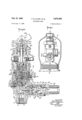
-Figure l1 is an elevational view of the discharge head in accordance with the invention imposition on a high pressure container (shown -broken away) with a portion of its-control' mechanism removed and a protective cylinder cap (shown in section) in position.
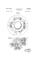
Figure 2 is 1a sectionalaview: taken along the line 2f2'of Figure v1 :but additionally showing control mecha- -nism in positiony I f Figure 3 is -a -top plan View `of, the discharge head with circles indicatingthe various positions of the open `mouth of the protective cap as it is placed over the discharge head into theposition of Figure l.l v
Figure 4 is a sectional view taken Y along the line yReferring to theidrawings, .there 'is shown in Figure 1 a discharge head 1 attached to the neck 2 of a high `pressure iluid container v4 sh'owl broken away. Aprotective cap 5 yis positioned Vabout 'the discharge head 1 which is shown the its ,upper portion removed and with acap ymember 6in position protecting the exposed `end of the container. A spare parts box 7 is positioned in the inner end ofA the protective cap 5 secured in position by a screw f8, the spare `parts box 7 being adapted toreceive replacement gaskets, valvemembers, etc.v
=In FigurejZithe completev discharge head 1 is` shown in vertical section and :includes'a generally vertically thereof exteriorly` threaded as indicatedfaty 12 for engagement with neck -2wof .thegcontairier ,4, the discharge head thereby closing the outlet of the container 4. At the lower end 11 ofvtheyhousing 10 is a vertically extendinginlet passagev 14 threaded asfindicated at 15 to receive the threaded upperend of a conventional syphon tube, not shown.
-Across the inlet-passage 14 is a partition member 16 extending across .,the width ofA the inlet 14, however,'by y, VApass "means, around-the partition Vmember 16 are pro-l yided ibyenlargingthe; .housing 10 a's-indicatedl atv 17,' a
charge is completed, the released pressure being utilized i to hold the pilot valve open to"y insure an' elective open-1 ingoperation. v Y 1 The discharge head in Vaccordi -1nc`se with the invention Vis of the type that may-be attached to a container of rate'suclr that a container so equipped-isgrated by the Underwriters Laboratories as equally'effectivejasa conlsquare portion ,l-bein'gprovided tto" facilitate engag'dement by. a t0ol, ,t,he y enlarged portion thereby'4 providing a verticallyextendingnuid passagel V19. Anupwardly I directed tubular extension 20 for the partition `member 16 fprins the :wallvof thefby-'pass passage19, or an alternativeconstrutionfis preferablyjus'ed '(see Figure 4)` in' i Y which the tubular lextension 20j-is made integral with the v housin ,-aA luralit .of verticall ext di i ftypoundsof carbon dioxide andlproduces'adischarge' g p 'y' y en ng passages 21 forming l'the by-pa'ss 19,;being bored or otherwisemade l therein'. At', thev top of fthje tubular 'extension "20? is fa main 'valve seat 22).forrned with a conventional rounded by forming outlet ud passage means. The tubular exwhich is adapted to slideably receive a guiding extension 26 for a safety check 27. About the safety check 27 is an outlet boss 29 in uid communication with 'the out- `let passages 24. On the outer end of the outlet boss 29 is a ring-shaped seat member 30 providing a safetvcheck seat 31 adapted to be engaged by the safety check 27, a
spring 33 being provided to abut between the outer surface of the tubular extension 20 and the inner surface of the safety check 27 normally urging the check valve 30 against its seat 31.. The seat member 30 is thread edly engaged in the inner surface of the outlet bossp29 as indicated at 32. The cross-sectional areas of the bypass 19, the valve seat 22, the outlet 24,and space 34 between the outer edge of the safety check 27 andthe seat member 30 are at least as great as the area of the inlet fluid passage 14. Y
' A conventional safety assembly 36 is engaged in a. boss 37 about a fluid passage 39 in uid communication with the inlet portion of the discharge head at the upper end of the by-pass 19, the safety disc assembly is threadedly engaged in the boss 37 as indicated at 40 and is sealed by a gasket 41, a rupturable sealing disc 42 normally closes the sealing disc 42. The sealing disc 42 is rupturable upon a pressure rise to a predetermined amount thereby venting the high pressure uid through a plural- M ity of opposed recoil prevention openings 44.
A filling assembly 45 is positioned on the housing 10 approximately at right angles to the sealing disc assembly 36 and is threadedly engaged in a filling boss 46 as indicated at 47, the fillingV bossr46 is positioned about a tiuid passage 49 in iiuid communication with the bypass 19 of the inlet portion of `the discharge head. The filling assembly includes a ring nut 50 having a filling valve seat 51 formed therein' engaged by a filling valve member 52. A gasket S4 seals against leaks. In
order to protect the filling assembly, a cap member 55 may be threadedly engaged with the filling boss 46 as indicated at 56, the cap member 55 being made with vent vapertures 57.
A cylinder is formed in an enlarged portion of the housing 10 to receive a piston valve member 62 yhaving onl its lower face a main valve contacting member 64 adapted to engage the main valve seat 22, the diameter of the piston valve member 62 being greater than the axial length thereof. The main valve contacting member `64 is made of any suitable material well-known in the art and may be apertured and secured in position in a recess 65 by a screw member 66 threadedly engaged in the body of the piston valve member 62 as indicated at 67. A bleed fluid passage 69 extends from the lower end of the piston valveY member 62 outwardly of the valve member 64 upwardlyadjacent the center of thc piston valve member 62 terminating in arecess 70. The outer edge of therecess 70 is provided with a bleed fluid valve seat 71. liow through the bleed fluid passage 69, the upper end thereof as indicated at 72 is of reduced diameter rather than making the entire length of the fiuid passage 69 of the same diameter so as to prevent the possibility of Y In order to predetermined the rate of freeze-up, frictionallosses, and to providel less chance y of clogging of theV reduced portion of the passage. The
piston valve member 62 is slideably guided against the wall of the cylinder 60 by side wall 74, a gasket recess 75 being provided to receive anv O-ringl gasket 76. It
should be noted that the,V axial length'of the side wall 74 1 is extremely short relative to the diameter of the piston valve member l'62, however, byreasonY of the equal dis'- tribution of the pressures acting on the piston valve member, `there is'notendency for it to cock and become jammed in thefcylinden This construction of the pis-v ton valve member 60 is very important in that it permits the usev of a considerably shorterrhousing than hereto foreusedf@ wall St) is recessed on its under surface as indicated at 82 to receive a Aspring 84 abutting at its upper end 85 against the bottom of the recess S2 and abutting at its lower end 86 against upper end 87 of the piston valve member 62.
In order to provide means for closing the bleed fluid passage 69, a downwardly directed bleed valve member 90 is positioned on the lower end of the end wall meniber 80 and provided with valve seat contacting material 91 apertured and secured in position in a recess 92 by means of a screw 94.
To vent fluid from behind the piston valve member 62, a plurality of vent passages 95 are provided extending 'from the Vunder side of the end wall member 8G to a recess 96 formed in the upper portion thereof. A partition member 97 apertured as indicated at 98 having a Ivent valve seat 99 on its inner side is threadedly engaged with the'wall of the recess as indicated at 190 to receive a vent valve member 101 having a stem 11a, the vent valve member 101, the downwardly directed bleed passage valve member 94 and the main valve member 64 being all in coaxial alignment with the center line of the inlet passage 14.
The end wall member 80 is provided with a iiange 102 having a downwardly directed portion 1134 adapted to overlie a flange 105 of the housing upper end 77. Sealingmeans is provided by an O-ring gasket 106 received lin a gasket recess 107. Another gasket recess 169 is adapted to receive an O-ring 111i to complete the seal for ,the housing upper end 77, the end 77 having its end surface cut away at anangle to provide an annular iiuid passage 111. On the upper end of the end wall mem Yber 80 is a tubular extension 112 forming a back pressure cylinder 114, fluid passage means for the seat back pressure cylinder 114 being provided from the outlet 24 through a horizontal passage 115, a vertical passage 116, the annular passage 111, a diagonal passage 117, and a vertical passage 118, the back pressure fluid passage being provided with a ball check valve 119 and a ball check Vvalve seat 120 placed at the intersection of the passages and 116. In order to maintain the ball check in pos1- tion so as to permit iiuid ow romthe outlet 24, but to vprevent fluid liiovv in the reverse direction, the check valve seat is placed about the passage 115 facing outwardly. A boss 121 is adapted to receive a nut V122 having a sprmg recess. 124 on the inner end thereof to force a spring 125 kinto engagement with the ballcheck 119. The outer end Vof the recessed nut 122 may be formed with an opening 126 toyreceive' a tool to secure the nut in position by threaded engagement as indicated at 127 with the inner surface of the boss 121.
i engaged between the upper surface of the partitionmern-y ber 97 'and the lower-surface of the back vpressure piston l130 to normally urge the backpressure piston 136 in the upper direction so that the operating rod 131 is clear of the vent valve member stem 101a. In order to retain the controlY piston 130 in its cylinder 114,`theinner sur-v face of the end of the cylinder wall is grooved as indicated at'137hr to receive afretaining member 139.
Venting means for the underside of the back pressure piston 130 are provided by meansof a iiuid passage 144 leading` to an annularv groove vformed about the lower end of the end wall Sti.- The annular4` groove 145 is so vpositioned that when the end wall member 80 is inserted iny position, theV annular ,groove 145 isvin alignment with aiiuid passage 146 extending'through upper end '77 of the housing 10. A boss 147 is positioned about the end of the passage 146 and is adapted to threadedly receive a check assembly 149, having a shoulder 150 with a valve seat 151 onits outer surface to receive a sector-shaped valve member 152.
The valve member 152 has an inwardly directed extension 154 to engage the inner end of a spring 155 abutting at its other end against the shoulder 150 adapted to hold the sector shaped valve member on its seat. This assembly permits the outward passage of uid released by operation of the vent valve member 101 or back pressure behind the piston 130. However, the valve member 152 prevents the entry of water or moisture into the various operating parts of the discharge head. It should be noted that the size of the passage 144 is such as to adequately relieve pressure vented behind the piston so that the piston 130 may be readily moved downward by the pressure of uid from the outlet transmitted to the top thereof through passages 115, 116, 111, and 118. The outer surface of the tubular extension 112 is threaded to receive the cap member 6 during transportation of the container with the discharge head attached and with the protective cap 5 in position.
The construction so far described is that shown in Figure 1 included Within the protective cap 5. The construction of the improved discharge head has been made such that it would iit within a standard sized protective cap 5 which has a 3-inch opening to engage the 3-inch diameter of the neck 2 of standard cylinders. In order to place the protective cap 5 in position over the construction so far described, it is necessary to move the cap member 5 around so that its opening may pass over the various bosses extending from the housing; Figure 3 is illustrated with circles and 141 showing the position of the mouth ofthe protective cap as it is slipped over the bosses,
circle 142 indicating the outer surface of the protectivek cap 35.
Because of the high discharge rate provided with the discharge head in accordance with the invention, it is necessary that the transportation and installation of the containers should be done in a non-armed condition; thus, with the construction so far described if an accidental discharge were had, the safety check valve member 27 would prevent fluid ow from the outlets 24.
An arming connector is attached to anend of a flexible bend which provides the connection between the. discharge head and the header of the usual fire extinguishing system. The arming connector includes a tubular member having one end 161 adapted to overlie and threadedly engaged with the outlet boss 29. The other end 162 of the tubular member 160 is `connected through ball swivel means with a fitting 165 at the end of a flexible bend 166. The swivel means is provided by a plurality of balls 167 engaged in cooperating grooves 169 and 170.
. Inner end 171 of the fitting 165 is sealed by an O-ringv gasket 172 in a gasket recess 174. The end 161 has a shoulder 175 provided with a valve seat 176 on the inner face thereof. A gasket 177 provides a seal between the outer side of the -shoulder 175 and the end of the boss-29.
Within the tubular member 169 is anarrriing member Q60 180 having an enlarged portion 181 with a vvalve member surface 182 on one side thereof. Extending beyond the valve fseat is an Aarming rod 15d, the Iarming rodbel jing of a length so that when the arming connector Vis in position on the outlet boss 29., bo-th the check lvalve 27 and the valve member 182 `are unseated. On the opposite end of the arming member 180 lfrom the arming rod 184 is a plurality of L.vane guiding membersA preferably four in number equally Vspaced and,v each having a anged portion 185 with a sector shoe 1864 having streamlined 1in-the direction of ow from the arming -rod V184 past the valve member 182 and thence along a Vthe flexible bend 166 and actuating the back pressure piston 130. However, in such a bank of containers it is necessary that one, and preferably two containers be provided with means to initiate a discharge whereby the slave container may be discharged by back pressure. The discharge heads for the control containers include means forvthe opening of the main valve 90 positioned at the top of the vertically extending housing 10 after the cap member 6 has been removed.
The control means `includes a tubular member 200 having its lower end 201 provided with a recess 2112 to receive a swivel ring 204, the swivel ring being engaged in `a cooperating recess 205 in a ring nut 206 threadedly engaged With end 112 of the housing 1i). Space 207 within the tubular member 20@ acts as a cylinder for the vrreciprocation of a piston 269 sealed with an O-ring 210 in aY gasket recess 211. An operating rod 212 at the bottom of the piston 211 is adapted to contact the back pressure piston 130.
Approximately in the middle of the tubular member 200 is a boss 214 at one side and another boss 215 opposite thereto. The boss 214 is adapted to receive a standard pressure leak check assembly 216, which may be alternatively replaced by a conventional electric discharge plug, not shown. The boss 215 is fitted with a connector 217 which may lead toa source of pressure releasable in -any conventional manner; or alternatively Amaybe closed with a plug when the electric discharge f plug is used-in the boss 214, or still inanother construction both the pressure connection means and the electric discharge plug may Vact on the piston 211.
At the upper endof the tubular member 290 is a boss 220 having a passage 221k therethrough with a reduced portion 2,22 serving as a guideway for a manual operating rod V224. The manual operating rod 224 is formed with a-shoulder 225 receiving'a spring 226 in abutment therewith and with the shoulder 222, the spring 226 vnormally urging the' operating rod224 upwardly out of contact with the piston V211. The` exterior of the boss 22u is threaded to receive an annular iiange nut 227 having a -recess 229 to receive a swivel ring 230 also engaged in a cooperating recess 231 of a fitting 232 carrying on its upper surfacea pair of upwardly directed extensions 234 apertured to ,receive a pin l235 providing e pivot means for a manual operating handle 236.
.Y The manual operating handle 236 is provided with a stop A2.",'7'and`a'carn surface 239 providing clearance as indicated at 240 for the normal inoperative position.
An enlargedportion 241 of the cam isfadapted, uponY e rod 22d-"for its Vdownward movement. The upper end of the operating rod `22.4 is'grooved to provide a gasket Y recess 243 adapted V,to receive-an O-ring gasket 244.
.A locking ypin 245 is inserted in an aperture through` .the Vupwardly directed 4:extensions 23d-iso. as to normally .preventthe operation of the handle 236 until thesafe'ty pinl isf first removed. A' lA chain 246 is provided to prevent the Vloss of thesafety pin, afterit Vhas been removed. in
o order to maintain the operating handle 236 in non-opera- H.tivey position, aspring 247; is providedsecured between the an outer surface of a radius to conform to that of the inner. surface 187 ofwthe tubular member 160, the inner surface..187 together withthe sector shoe .186 forming Y guiding means'for the arming Ymember 189. lIt should pivot pin Y235 yand ventional manner.-
In the'operation of thedischarge head, pressure mayy be admitted to thepiston 211 through'pressunizing fitting E217 orybymeans rofthe actuation kofv anv elect-ric` discharge e `plug positioned in the boss 214. 1n the event-thepresbe noted thatthe-surfaceofthearmng lmember '180 $135; Sure SIISUCSU t0 'move ille' vPSSJIl'M1edQWnfVWHY;
the operating handle236 in a icon aeralre assistance may be had .by operation of the manual operating handle *236 or, alternatively, the actuation of `the piston 211 downwardly may be had solely by movement of the operating handle 236. The downward movement of the piston 211 moves back pressure piston 130 downwardly in contact with the stem of the vent valve member 101 thereby releasing fluid through passages 95V from ythe space in back of the piston valve member 62. The pressure of fiuid in the by-pass 19 `on the face of piston valve member 62 moves it upwardly -against the action of the spring 84 and causes seating of the bleed valve member 9i on the bleed valve seat 71, thus, preventing further ilow of fluid through the passages 69 and 72 to the rear of the piston.
The piston valve member 90 is pneumatically locked in the open position by pressure of uid on the face thereof irrespective of whether or not the vent valve member 101 is maintained in the open position, the force of the spring 84 being predetermined so that the piston valve v member 62 will remain in the open position until the pressure within the inlet 14 drops to a desired value when substantially all of the contents of the container 4 have been evacuated. After a discharge the container 4 may be relled with re extinguishing agent through the iilling assembly 45 through which fluid will flow inwardly down through by-pass 19 and inlet passage 14 into container 4. At the same time fluid will flow through the bleed passages 69 and 72 behind the piston valve member 62 urging the main valve member 64 against its `seat 22.
While the invention has been described and illustrated with respect to a specific embodiment thereof, it will be understood that other embodiments may be resorted to without departing from the invention. form of the invention set out above should be considered as illustrative and not as limiting the scope of the following claims:
We claim:
l. A discharge head for use with a'high pressure uid container, the discharge head comprising a generally vertically extending housing, the lower end of the housing adapted to close the outlet of a high pressure container with which it is used, the lower end of the housing having a vertically extending inlet uid passage, apartition member extending across the passage, the upper portion of the housing enlarged in diameter thereby providing uid passage means by-passing said partition member, said by-pass passage offset from the inlet passage, an upwardly directed tubular extension for the partition member in alignment with the inlet passage, the exterior of the tubular extension with the inner wall of the enlarged portion of the housing defining said lluid passage by-pass, a main valve'seat formed at the upper edge of the tubular extension, the main valve seat in alignment with the inlet passage, the sidewall of the tubular extension aperture forming outlet uid passage means, a Ihorizontal extension for the housing defining an outlet boss in uid communication with the outlet passage, a piston valve member carrying a main valve seat contactingmember at the lower end thereof and adapted to engage the vmain valve seat, the diameter of the piston Valve member -greater than the axial length thereof, the inner wall of the housing above the main valve seat forming a main cylinder receiving the piston valve member, bleed fluid passage means extending from the lower end of the piston valve member outwardly of the main valve seat contacting member to the upper endrof 4the piston valve member, a bleed valve seat about the upper end of said bleed Vhuid passage on said piston valve member, an end wall member closing the upper end ofthe main cylinder, a downwardly directed bleed valve member positioned on said end wall member and adapted to be contacted by saidbleed passage valve seat to close the bleed passage, the end wall having f a recessY therein in its upper portion, an apertured partit non member closing the recess, vent fluid passage. means Therefore, the
the recess, a ventV valve seat about the aperture on the lower side of the recess' partition member, `and, a Vent valve member positioned in said recess and adapted to engage the vent valve seat, the main valve member, the bleed passage valve member and the vent valve member being in coaxial alignment with the center line of the inlet passage, whereby the vent valve member may be unseated so that pressure may be vented behind the piston and the main valve opened by pressure on the face of the piston and the bleed valve passage is closed to prevent loss of fluid therethrough.
2. A discharge head for use with a high pressure lluid container, the discharge head comprising a generally vertically extending honsing, the lower end of the housing adapted to close the outlet of a high pressure container with which it is used, the lower end of the housing having a vertically extending inlet fluid passage, a partition member extending across the passage, the upper portion of the housing enlarged in diameter thereby providing fluid passage means lay-passing said partition member, said bypass passage offset from the inlet passage, an upwardly directed tubular extension for the partition member in alignment with the inlet passage, the exterior of the tubular extension with the inner wall of the enlarged portion of the housing deiining said fluid passage by-pass, a main valve seat formed at the upper edge of the tubular extension, the main valve seat in alignment with the inlet passage, the sidewall of the tubular extension apertured forming outlet iluid passage means, a horizontal extension for the housing defining an outlet boss in uid communication with the outletpassage, a pair of horizontal extensions forrthe housing in iluid communication with the outlet passage, one of the pair of extensions dening a safety disc plug boss and the other of the pair of extensions detining a lling connection` boss, a piston valve member carrying a main valve seat contacting member at the lower end thereof and adapted to engage the main valve seat, the diameter of the piston valve member greater than the axial length thereof, the inner wall of the housing above the main valve seat forming a main passage means extending from the lower end of the piston valve member outwardly of the main valve seat contacting member to the upper end of the piston valve member, a bleed valve seat about the upper end of said bleed fluid passage on said piston valve member, an end wall member closing the upper end of the main cylinder, a downwardly directed bleed valve member positioned on said end wall member and adapted to be contacted by said bleed passage valve seat to close the bleed passage, the end wall having a recess therein in its upper portion, an apertured partition member closing the recess, vent fluid passage means extending through said end wall mem- ,berfrom the lower end thereof outwardly of said bleed valve member to the rceess, a vent valve seat about the aperture on the lower side of the recess partition member, and a vent valve member positioned in said recess and adapted to engage the vent valve seat, the main valve member, the bleed passage valve member and the vent valve member being in coaxial alignment with the center line of the inlet passage, whereby the Vent valve member may be unseated so that pressure may be vented behind the piston and the main valve opened by pressure on the face of the piston and the bleed valve passage is closed to prevent loss of fluidtherrethrough.
3. A discharge head for use with a high pressure fluid container, the discharge head comprising a generally 9 l viding fluid passage means by-passing said partition mem ber, an upwardly directed tubular extension for the partition member, the exterior of the tubular extension with the inner wall of the enlarged portion of the housing defining said uid passage by-pass, a main valve seat formed at the upper edge of the tubular extension and defining inlet and outlet portions of the passage, a horizontal extension for the housing defining an outlet boss in fluid communication with the outlet passage, a piston valve member carrying a main valve seat contacting member at the lower end thereof and adapted to engage the main valve seat, the diameter of the piston valve member greater than the axial length thereof, the inner wall of the housing above the main valve seat forming a main cylinder receiving the piston valve member, bleed fluid passage means extending from the lower end of the piston valve member outwardly of the main valve seat contacting member to the upper end of the piston valve member, an extension for the piston valve member, a bleed valve seat on the piston valve member extension about the upper end of said bleed fluid passage, an end wall member closing the upper end of the main cylinder, a downwardly depending extension for the end wall member, a downwardly directed bleed valve member positioned on said end wall member extension and adapted to be contacted by said bleed passage valve seat to close the bleed passage, the end wall having a recess therein in its upper portion, an apertured-partition member closing the recess, vent uid passage means extending through v 10 said end wall member from the lower end thereof to the recess, a vent valve seat about the aperture on the lower side of the recess partition member, and a vent valve member positioned in said recess and adapted to engage the vent valve seat, a spring urging the piston valve member in main Valve seat engaging position, the spring having one end overlying the piston-valve member extension, the other end of the spring overlying'the end wall extension, the main valve member and the vent valve member being in coaxial alignment with the center line of the inlet passage, whereby the vent valve member may be unseat'ed so that pressure may be vented behind 'the piston and the main valve opened by pressure on the face of the piston.
References Cited in the le of this patent UNITED VSTATES PATENTS 880,030 Leavitt Feb. 25, 1908 980,624 Gale Jan. 3, 1911 1,228,653 De Spirito June 5, 1917 1,651,689 Freeze Dec. 6, 1927 2,162,096 Marmorek June 13, 1939 2,492,165 Mapes Dec. 27, 1949 2,518,299 Fernandez Aug. 8, 1950 2,780,296 Heigis Feb. 5, 1957 2,830,784 Placette Apr. 15, 1958 FOREIGN PATENTS France May 1957
Priority Applications (1)
| Application Number | Priority Date | Filing Date | Title |
|---|---|---|---|
| US67727657 US2972466A (en) | 1957-08-09 | 1957-08-09 | Discharge head |
Applications Claiming Priority (1)
| Application Number | Priority Date | Filing Date | Title |
|---|---|---|---|
| US67727657 US2972466A (en) | 1957-08-09 | 1957-08-09 | Discharge head |
Publications (1)
| Publication Number | Publication Date |
|---|---|
| US2972466A true US2972466A (en) | 1961-02-21 |
Family
ID=24718047
Family Applications (1)
| Application Number | Title | Priority Date | Filing Date |
|---|---|---|---|
| US67727657 Expired - Lifetime US2972466A (en) | 1957-08-09 | 1957-08-09 | Discharge head |
Country Status (1)
| Country | Link |
|---|---|
| US (1) | US2972466A (en) |
Cited By (11)
| Publication number | Priority date | Publication date | Assignee | Title |
|---|---|---|---|---|
| US3411523A (en) * | 1965-07-26 | 1968-11-19 | Parker Hannifin Corp | Pressure regulator |
| EP0027310A3 (en) * | 1979-10-15 | 1981-10-28 | Caterpillar Tractor Co. | Fire extinguishing system |
| US5836352A (en) * | 1996-06-06 | 1998-11-17 | Pgi International, Ltd. | Environmental fill valve |
| US5996625A (en) * | 1996-06-05 | 1999-12-07 | Taema | Assembly for controlling and dispensing gas for a container of pressurized gas |
| US20090301581A1 (en) * | 2008-04-23 | 2009-12-10 | Macneal James R | Pressurized gas containing system |
| USD657849S1 (en) * | 2010-12-03 | 2012-04-17 | Finish Thompson, Inc. | Discharge head |
| US20120090853A1 (en) * | 2009-04-03 | 2012-04-19 | Managed Pressure Operations Pte. Ltd. | Drill pipe connector |
| USD658273S1 (en) * | 2010-12-03 | 2012-04-24 | Finish Thompson, Inc. | Discharge head |
| USD658274S1 (en) * | 2010-12-03 | 2012-04-24 | Finish Thompson, Inc. | Discharge head |
| EP3222329A1 (en) * | 2016-03-22 | 2017-09-27 | Kidde Technologies, Inc. | Automatic fire extinguisher system having a safety assembly |
| US20220178464A1 (en) * | 2019-04-26 | 2022-06-09 | Luxembourg Patent Company S.A. | Lever valve with securing hook |
Citations (10)
| Publication number | Priority date | Publication date | Assignee | Title |
|---|---|---|---|---|
| US880030A (en) * | 1907-02-16 | 1908-02-25 | Bliss E W Co | Starting-valve for automobile torpedoes. |
| US980624A (en) * | 1910-05-16 | 1911-01-03 | Howard A Broughton | Safety train-air-line cut-out cock. |
| US1228653A (en) * | 1913-08-21 | 1917-06-05 | James F De Spirito | Flushing device. |
| US1651689A (en) * | 1926-03-17 | 1927-12-06 | Otis A Freeze | Pressure-operated valve |
| US2162096A (en) * | 1938-08-06 | 1939-06-13 | Auto Cream Whip Corp | Device for producing whipped cream |
| US2492165A (en) * | 1945-12-21 | 1949-12-27 | Specialties Dev Corp | System for dispensing fluids |
| US2518299A (en) * | 1945-06-16 | 1950-08-08 | Dan T Fernandez | Coupling and servicing assembly |
| US2780296A (en) * | 1953-01-19 | 1957-02-05 | Specialties Dev Corp | Fluid dispensing system |
| FR1146390A (en) * | 1956-04-03 | 1957-11-12 | Safety device for connection taps for gas pipes or appliances and pressure-reducing valve for gas cylinders or the like fitted with this device | |
| US2830784A (en) * | 1954-09-30 | 1958-04-15 | Placette Theodore | General purpose flow valve with alternative fluid pressure or manual control |
-
1957
- 1957-08-09 US US67727657 patent/US2972466A/en not_active Expired - Lifetime
Patent Citations (10)
| Publication number | Priority date | Publication date | Assignee | Title |
|---|---|---|---|---|
| US880030A (en) * | 1907-02-16 | 1908-02-25 | Bliss E W Co | Starting-valve for automobile torpedoes. |
| US980624A (en) * | 1910-05-16 | 1911-01-03 | Howard A Broughton | Safety train-air-line cut-out cock. |
| US1228653A (en) * | 1913-08-21 | 1917-06-05 | James F De Spirito | Flushing device. |
| US1651689A (en) * | 1926-03-17 | 1927-12-06 | Otis A Freeze | Pressure-operated valve |
| US2162096A (en) * | 1938-08-06 | 1939-06-13 | Auto Cream Whip Corp | Device for producing whipped cream |
| US2518299A (en) * | 1945-06-16 | 1950-08-08 | Dan T Fernandez | Coupling and servicing assembly |
| US2492165A (en) * | 1945-12-21 | 1949-12-27 | Specialties Dev Corp | System for dispensing fluids |
| US2780296A (en) * | 1953-01-19 | 1957-02-05 | Specialties Dev Corp | Fluid dispensing system |
| US2830784A (en) * | 1954-09-30 | 1958-04-15 | Placette Theodore | General purpose flow valve with alternative fluid pressure or manual control |
| FR1146390A (en) * | 1956-04-03 | 1957-11-12 | Safety device for connection taps for gas pipes or appliances and pressure-reducing valve for gas cylinders or the like fitted with this device |
Cited By (20)
| Publication number | Priority date | Publication date | Assignee | Title |
|---|---|---|---|---|
| US3411523A (en) * | 1965-07-26 | 1968-11-19 | Parker Hannifin Corp | Pressure regulator |
| EP0027310A3 (en) * | 1979-10-15 | 1981-10-28 | Caterpillar Tractor Co. | Fire extinguishing system |
| US5996625A (en) * | 1996-06-05 | 1999-12-07 | Taema | Assembly for controlling and dispensing gas for a container of pressurized gas |
| US5836352A (en) * | 1996-06-06 | 1998-11-17 | Pgi International, Ltd. | Environmental fill valve |
| US9097387B2 (en) | 2008-04-23 | 2015-08-04 | Praxair Technology, Inc. | Pressurized gas containing system |
| US20090301581A1 (en) * | 2008-04-23 | 2009-12-10 | Macneal James R | Pressurized gas containing system |
| US9562650B2 (en) | 2008-04-23 | 2017-02-07 | Praxair Technology, Inc. | Pressurized gas containing system |
| US8336577B2 (en) * | 2008-04-23 | 2012-12-25 | Praxair Technology, Inc. | Pressurized gas containing system |
| US9091396B2 (en) | 2008-04-23 | 2015-07-28 | Praxair Technology, Inc. | Pressurized gas containing system |
| US20120090853A1 (en) * | 2009-04-03 | 2012-04-19 | Managed Pressure Operations Pte. Ltd. | Drill pipe connector |
| US9284800B2 (en) * | 2009-04-03 | 2016-03-15 | Managed Pressure Operations Pte Ltd. | Drill pipe connector |
| USD657849S1 (en) * | 2010-12-03 | 2012-04-17 | Finish Thompson, Inc. | Discharge head |
| USD658274S1 (en) * | 2010-12-03 | 2012-04-24 | Finish Thompson, Inc. | Discharge head |
| USD658273S1 (en) * | 2010-12-03 | 2012-04-24 | Finish Thompson, Inc. | Discharge head |
| EP3222329A1 (en) * | 2016-03-22 | 2017-09-27 | Kidde Technologies, Inc. | Automatic fire extinguisher system having a safety assembly |
| US10226656B2 (en) | 2016-03-22 | 2019-03-12 | Kidde Technologies, Inc. | Automatic fire extinguisher system having a safety assembly |
| US10987530B2 (en) | 2016-03-22 | 2021-04-27 | Kidde Technologies, Inc. | Automatic fire extinguisher system having a safety assembly |
| EP4008410A1 (en) * | 2016-03-22 | 2022-06-08 | Kidde Technologies, Inc. | Automatic fire extinguisher system having a safety assembly |
| US20220178464A1 (en) * | 2019-04-26 | 2022-06-09 | Luxembourg Patent Company S.A. | Lever valve with securing hook |
| US12117097B2 (en) * | 2019-04-26 | 2024-10-15 | Rotarex S.A. | Lever valve with securing hook |
Similar Documents
| Publication | Publication Date | Title |
|---|---|---|
| US4285495A (en) | Safety valve | |
| US3048194A (en) | Fire extinguisher head assembly | |
| ES2215914T3 (en) | INSTANT OPERATING VALVE RESISTANT TO SHOCK. | |
| US4073464A (en) | Cylinder valve for gas fire extinguishing system | |
| TWI607781B (en) | A fire suppression system | |
| US3903914A (en) | Gas release valve | |
| JPH0560126B2 (en) | ||
| CA1319584C (en) | Valve | |
| US6886593B2 (en) | Safety valve with pressure indicator | |
| EP0025150A1 (en) | Temperature controlled valve mechanism and method | |
| US3653406A (en) | Brake cylinder pressure retaining valve | |
| US2717042A (en) | Impact operated valve | |
| US2548750A (en) | Indicator | |
| US3052304A (en) | Fire extinguishing system | |
| US2719532A (en) | Valve | |
| US2363521A (en) | Valve device | |
| US3285288A (en) | Safety shut-off valve | |
| US2383961A (en) | Fluid release device | |
| US4136851A (en) | Valve for fire extinguishing system of gas distribution type | |
| JPS6039580B2 (en) | failure indication device | |
| US6053256A (en) | Fire extinguishing system | |
| US4559970A (en) | Pilot control relay valve apparatus | |
| US2674326A (en) | Pressure assisted fire extinguisher discharge valve | |
| US3532116A (en) | Brake cylinder pressure retaining valve | |
| US2607367A (en) | Valve |