US2961830A - Hydraulic torque converter - Google Patents
Hydraulic torque converter Download PDFInfo
- Publication number
- US2961830A US2961830A US632688A US63268857A US2961830A US 2961830 A US2961830 A US 2961830A US 632688 A US632688 A US 632688A US 63268857 A US63268857 A US 63268857A US 2961830 A US2961830 A US 2961830A
- Authority
- US
- United States
- Prior art keywords
- torque converter
- hydraulic torque
- converter
- blades
- dundore
- Prior art date
- Legal status (The legal status is an assumption and is not a legal conclusion. Google has not performed a legal analysis and makes no representation as to the accuracy of the status listed.)
- Expired - Lifetime
Links
Images


Classifications
-
- F—MECHANICAL ENGINEERING; LIGHTING; HEATING; WEAPONS; BLASTING
- F16—ENGINEERING ELEMENTS AND UNITS; GENERAL MEASURES FOR PRODUCING AND MAINTAINING EFFECTIVE FUNCTIONING OF MACHINES OR INSTALLATIONS; THERMAL INSULATION IN GENERAL
- F16H—GEARING
- F16H41/00—Rotary fluid gearing of the hydrokinetic type
- F16H41/24—Details
- F16H41/26—Shape of runner blades or channels with respect to function
Definitions
- HYDRAULIC TORQUE CONVERTER Filed Jan. '7, 1957 19 Sheets-$heet I5 PUMP- FIL rs Nov. 29, 1960 M. w. DUNDORE ETAL 2,961,830 HYDRAULIC TORQUE CONVERTER Filed Jan. 7, 1957 RBINE ,Z fid 1: 21 071 ard/(12W fiu/zdor'a 31917720274 Cafe/717211:
- Winn/tr WDazzda re. 4) 9710224 dfcrza de 1'.
- One object of the invention is to provide a hydraulic torque converter of the single stage, single phase type which is more particularly designed for industrial equipment such as, for example, power shovels, hoists, draglines, end loaders, and wheeled and tracked vehicles.
- a further object is the provision of a converter of the type indicated which is characterized by a relatively flat, primary torque curve and holds the power source, engine or motor, at or near the governed speed as the speed of the output shaft varies from racing to stall or zero speed, thus permitting the use of the maximum possible horsepower at all times.
- a further object is to provide a converter as above which embodies a novel shape of toroidal circuit that, in conjunction with positionings of the impeller and turbine blades, enables the liquid head of the turbine to oppose that of the impeller at relatively high speed ratios, thereby effecting a sudden shut off of flow in the circuit and a substantial reduction in the transmitted torque.
- a further object is to devise a converter as above and a connected cooler through which a basic, forced circulation is maintained at all times which is reinforced by the natural circulation in the converter circuit at relatively low speed ratios when maximum heat dissipation is required.
- a further object is to devise a converter of the type set forth in which the stator blades are adjustaby rotatable to accurately control the amount and direction of the liquid flow therebetween, thereby uniformly varying the torque absorption and transmission capacity of the unit and enabling the available horsepower to be divided as desired between the shaft connected to the converter and auxiliary equipment connectible to the power source.
- a further object is to provide an hydraulic torque converter having a blade system so designed that several combinations of impeller and turbine blades related to a common stator in the same unit will produce variations in torque capacity at a given speed of 2:1.
- a further object is to provide a single stage, rotating housing type of hydraulic torque converter which includes an impeller having principal blades radial curved forwardly in the direction of rotation and relatively shorter blades interposed between each pair of adjacent, principal blades to reduce the secondary flow between the principal blades and provide a larger torque capacity for any given principal blade shape and outlet angle.
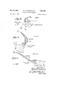
- Fig. l is a fragmentary, longitudinal elevation in section of one form of the hydraulic torque converter.
- Figs. 2, 3 and 4 are sectional elevations to reduced scale of the impeller, turbine and stator, respectively, all as shown in Fig. 1.
- Figs. 5, 6 and 7 are side elevations as viewed, respectively, in the directions of the correspondingly numbered arrows in Figs. 2, 3 and 4, parts being broken away to show a number of blades in each instance.
- Fig. 8 is an enlarged, schematic and fragmentary view of the turbine as viewed in Fig. 6 showing the limiting positions of the apertures through which the cooling flow is tapped from the toroidal circuit.
- Fig. 9 is a schematic View of the external cooling circuit for the converter shown in Fig. 1.
- Fig. 10 is a schematic illustration of the converter shown in Fig. 1 showing the shape of the toroidal circuit, the relation of the component bladed members, and the position of the mean stream flow line of the circuit.
- Fig. 11 is an exploded and developed, schematic view showing the relationship and mean stream flow line shapes of the impeller, turbine and stator blades in the Fig. 1 converter and also the Fig. 25 converter when the stator blades thereof are fully open.
- Figs. 12, 13 and 14 show vectorially the direction of the relative approach velocities of the working liquid in relation to the inlet tips of the impeller, turbine and stator blades, respectively.
- Figs. 15 and 16 are schematic, dimensioned views of the outer and inner, unbladed bends of the toroidal circuit.
- Figs. 17, 18 and 19 are enlarged, schematic views of several impeller core blades when viewed from the impeller ring side or in the direction of the arrow 5 in Fig. 2, of several turbine core blades when viewed from the turbine ring side or oppositely to the arrow 6 in Fig. 3, and of several stator blades when viewed from the stator core ring side or in the direction of the arrow 7 in Fig. 4, all respectively, each with suggested inlet and outlet angles (a, and a a suggested distance (b) between the impeller blades at their inlet, and a suggested distance (0) between the turbine and stator blades, respectively, at their outlets.
- suggested inlet and outlet angles a, and a a suggested distance (b) between the impeller blades at their inlet, and a suggested distance (0) between the turbine and stator blades, respectively, at their outlets.
- Figs. 20, 21 and 22 are dimensioned views of typical impeller, turbine and stator blades, respectively, the dimensions being tabulated with reference to X- and Y-axes and each blade being considered as lying along the X-axis, these views being related to the comparable blades shown in Figs. l7, l8 and 19, respectively.
- Fig. 23 shows typical performance curves of a 15" hydraulic torque converter embodying the invention and having a specific torque rating of 200 pds. ft.
- Fig. 24 shows further performance curves of the torque converter referred to in Fig. 23 when matched to a diesel engine having 126 net horsepower output at 2200 r.p.m., and embodying the blading shown in Figs. 17 to 22, inclusive.
- Fig. 25 is a fragmentary, longitudinal section of a modification of the converter in which the stator blades are adjustably mounted for variable control on the amount and direction of liquid flow in the torus circuit.
- Fig. 26 is a schematic view showing fully opened and closed positions of two adjacent, stator blades in Fig. 25.
- Fig. 27 is a section along the line 2727 in Fig. 25.
- Fig. 28 shows characteristic efficiency and torque curves in relation to variations in the stator blade positions for a typical converter of the Fig. 25 type.
- Figs. 29 to 31, inclusive are performance curves of a typical Fig. 25 converter when connected to an engine providing 91.5 hp. at 1800 r.p.m. and showing, respec-
Description
Nov. 29, 1960 Filed Jan. 7, 1957 M. W. DUNDORE ETAL HYDRAULIC TORQUE CONVERTER 19 Sheets-Sheet l In 061160 r'a War/4:72 W00 radon.
Nov. 29, 19 M. w. DUNDORE ETAL 2,961,830
HYDRAULIC TORQUE CONVERTER Filed Jan. 7, 1957 19 Sheets-Sheet 2 Nov. 29, 1960 M. w. DUNDORE ETAL 2,961,330
HYDRAULIC TORQUE CONVERTER Filed Jan. '7, 1957 19 Sheets-$heet I5 PUMP- FIL rs Nov. 29, 1960 M. w. DUNDORE ETAL 2,961,830 HYDRAULIC TORQUE CONVERTER Filed Jan. 7, 1957 RBINE ,Z fid 1: 21 071 ard/(12W fiu/zdor'a 31917720274 Cafe/717211:
19 Sheets-Sheet 4 Nov. 29, 1960 M. w. DUNDORE ETAL 2,961,830
- HYDRAULIC TORQUE CONVERTER Filed Jan. 7, 1957 19 Sheets-Sheet 5 $77770? FIX Ea THREINE rRmwsPo/nw T/ON Nov. 29, 1960 M. w. DUNDORE ETAL 2,961,830
HYDRAULIC TORQUE CONVERTER l9 Sheets-Sheet 6 Filed Jan. 7, 1957 HNGLES IMPELL E? 5 m Him T wfi 0 5f 6 H 2% w y w fl 5 p 0%.6 i w oZA/I a 0 10 on 4 Wm u\ 0% M? M ,M fi em w a W l a/ Nov. 29, 1 M. w. DUNDORE ETAL 2,961,830
HYDRAULIC TORQUE CONVERTER l9 Sheets-Sheet 7 Filed Jan. '7, 1957 TURBINE I I I I I 1 I xii 0 1950 M. w. DUNDORE ETAL 2, 61,830
HYDRAULIC TORQUE CONVERTER l9 Sheets-Sheet 8 Filed Jan. 7, 1957 Nov. 29, 19 M. w. DUNDORE ET AL 2,961,830
HYDRAULIC TORQUE CONVERTER Filed Jan. 7, 1957 19 Sheets-Sheet 12 INPUT SPEEa- TORQUE TORQUE INPU 7' 5PEED P. T F EFFICIENCY 60 7'0 25/?0 51 550 Rnrm- [N .M m I IIVGL5 .5 CONUERTE (NE S17E50 EEPOWER vsa 1-5 7 our war a e-0 vZR/ L Nov. 29, 1960 M. w. DUNDORE ETAL 2,961,830
HYDRAULIC TORQUE CONVERTER Filed Jan. 7. 19s? 19 Sheets-Sheet 13 N 1 w. DUNDORE ETAL 2,961,830
HYDRAULIC TORQUE CONVERTER 19 Sheets-Sheet 14 Filed Jan. 7, 1957 Nov. 29, 19 M. w. DUNDORE ETAL 2,961,830 HYDRAULIC TORQUE CONVERTER Filed Jan. 7, 1957 19 Sheets-Sheet 15 5 I7 OPf/Vl N6 N00 lava Nov. 29, 1960 M. w. DUND'ORE ETAL 2,961,830
HYDRAULIC TORQUE CONVERTER Filed Jan. '7, 1957 19 Sheets-Sheet 16 v III/7U OUT PUT FOWR [N5 SPEED H P ENGINE 60VERNED a flftar g n fora.
Nov. 29, 1960 M. w. DUNDORE ETAL 2,961,830
HYDRAULIC TORQUE CONVERTER Filed Jan. '7, 1957 v 19 Sheets-Sheet 17 IMP5LLER Earn TION Jru/erzfo r15.
Winn/tr: WDazzda re. 4) 9710224 dfcrza de 1'.
19 Sheets-Sheet 19 M. W. DUNDORE ETAL HYDRAULIC TORQUE CONVERTER Nov. 29, 1960 Filed Jan. 7, 1957 Patented Nov. 29, 1960 HYDRAULIC TORQUE CONVERTER Marvin W. Dundore and Raymond C. Schneider, Rockford, lll., assignors to Twin Disc Clutch Company, Racine, Wis., a corporation of Wisconsin Filed Jan. 7, 1957, Ser. No. 632,688
7 Claims. (Cl. 60-54) Our invention relates to a hydraulic torque converter of the single stage, rotating housing type which is characterized by an improved design.
One object of the invention is to provide a hydraulic torque converter of the single stage, single phase type which is more particularly designed for industrial equipment such as, for example, power shovels, hoists, draglines, end loaders, and wheeled and tracked vehicles.
A further object is the provision of a converter of the type indicated which is characterized by a relatively flat, primary torque curve and holds the power source, engine or motor, at or near the governed speed as the speed of the output shaft varies from racing to stall or zero speed, thus permitting the use of the maximum possible horsepower at all times.
A further object is to provide a converter as above which embodies a novel shape of toroidal circuit that, in conjunction with positionings of the impeller and turbine blades, enables the liquid head of the turbine to oppose that of the impeller at relatively high speed ratios, thereby effecting a sudden shut off of flow in the circuit and a substantial reduction in the transmitted torque.
A further object is to devise a converter as above and a connected cooler through which a basic, forced circulation is maintained at all times which is reinforced by the natural circulation in the converter circuit at relatively low speed ratios when maximum heat dissipation is required.
A further object is to devise a converter of the type set forth in which the stator blades are adjustaby rotatable to accurately control the amount and direction of the liquid flow therebetween, thereby uniformly varying the torque absorption and transmission capacity of the unit and enabling the available horsepower to be divided as desired between the shaft connected to the converter and auxiliary equipment connectible to the power source.
A further object is to provide an hydraulic torque converter having a blade system so designed that several combinations of impeller and turbine blades related to a common stator in the same unit will produce variations in torque capacity at a given speed of 2:1.
A further object is to provide a single stage, rotating housing type of hydraulic torque converter which includes an impeller having principal blades radial curved forwardly in the direction of rotation and relatively shorter blades interposed between each pair of adjacent, principal blades to reduce the secondary flow between the principal blades and provide a larger torque capacity for any given principal blade shape and outlet angle.
These and further objects of the invention will be set forth in the following specification, reference being had to the accompanying drawings, and the novel means by which the objects are effectuated will be definitely pointed out in the claims.
In the drawings:
Fig. l is a fragmentary, longitudinal elevation in section of one form of the hydraulic torque converter.
Figs. 2, 3 and 4 are sectional elevations to reduced scale of the impeller, turbine and stator, respectively, all as shown in Fig. 1.
Figs. 5, 6 and 7 are side elevations as viewed, respectively, in the directions of the correspondingly numbered arrows in Figs. 2, 3 and 4, parts being broken away to show a number of blades in each instance.
Fig. 8 is an enlarged, schematic and fragmentary view of the turbine as viewed in Fig. 6 showing the limiting positions of the apertures through which the cooling flow is tapped from the toroidal circuit.
Fig. 9 is a schematic View of the external cooling circuit for the converter shown in Fig. 1.
Fig. 10 is a schematic illustration of the converter shown in Fig. 1 showing the shape of the toroidal circuit, the relation of the component bladed members, and the position of the mean stream flow line of the circuit.
Fig. 11 is an exploded and developed, schematic view showing the relationship and mean stream flow line shapes of the impeller, turbine and stator blades in the Fig. 1 converter and also the Fig. 25 converter when the stator blades thereof are fully open.
Figs. 12, 13 and 14 show vectorially the direction of the relative approach velocities of the working liquid in relation to the inlet tips of the impeller, turbine and stator blades, respectively.
Figs. 15 and 16 are schematic, dimensioned views of the outer and inner, unbladed bends of the toroidal circuit.
Figs. 17, 18 and 19 are enlarged, schematic views of several impeller core blades when viewed from the impeller ring side or in the direction of the arrow 5 in Fig. 2, of several turbine core blades when viewed from the turbine ring side or oppositely to the arrow 6 in Fig. 3, and of several stator blades when viewed from the stator core ring side or in the direction of the arrow 7 in Fig. 4, all respectively, each with suggested inlet and outlet angles (a, and a a suggested distance (b) between the impeller blades at their inlet, and a suggested distance (0) between the turbine and stator blades, respectively, at their outlets.
Figs. 20, 21 and 22 are dimensioned views of typical impeller, turbine and stator blades, respectively, the dimensions being tabulated with reference to X- and Y-axes and each blade being considered as lying along the X-axis, these views being related to the comparable blades shown in Figs. l7, l8 and 19, respectively.
Fig. 23 shows typical performance curves of a 15" hydraulic torque converter embodying the invention and having a specific torque rating of 200 pds. ft.
Fig. 24 shows further performance curves of the torque converter referred to in Fig. 23 when matched to a diesel engine having 126 net horsepower output at 2200 r.p.m., and embodying the blading shown in Figs. 17 to 22, inclusive.
Fig. 25 is a fragmentary, longitudinal section of a modification of the converter in which the stator blades are adjustably mounted for variable control on the amount and direction of liquid flow in the torus circuit.
Fig. 26 is a schematic view showing fully opened and closed positions of two adjacent, stator blades in Fig. 25. Fig. 27 is a section along the line 2727 in Fig. 25.
Fig. 28 shows characteristic efficiency and torque curves in relation to variations in the stator blade positions for a typical converter of the Fig. 25 type.
Figs. 29 to 31, inclusive, are performance curves of a typical Fig. 25 converter when connected to an engine providing 91.5 hp. at 1800 r.p.m. and showing, respec-
Priority Applications (1)
| Application Number | Priority Date | Filing Date | Title |
|---|---|---|---|
| US632688A US2961830A (en) | 1957-01-07 | 1957-01-07 | Hydraulic torque converter |
Applications Claiming Priority (1)
| Application Number | Priority Date | Filing Date | Title |
|---|---|---|---|
| US632688A US2961830A (en) | 1957-01-07 | 1957-01-07 | Hydraulic torque converter |
Publications (1)
| Publication Number | Publication Date |
|---|---|
| US2961830A true US2961830A (en) | 1960-11-29 |
Family
ID=24536515
Family Applications (1)
| Application Number | Title | Priority Date | Filing Date |
|---|---|---|---|
| US632688A Expired - Lifetime US2961830A (en) | 1957-01-07 | 1957-01-07 | Hydraulic torque converter |
Country Status (1)
| Country | Link |
|---|---|
| US (1) | US2961830A (en) |
Cited By (10)
| Publication number | Priority date | Publication date | Assignee | Title |
|---|---|---|---|---|
| US3027720A (en) * | 1958-06-19 | 1962-04-03 | Gen Motors Corp | Transmission |
| US3118279A (en) * | 1964-01-21 | goudy | ||
| US3232580A (en) * | 1963-07-18 | 1966-02-01 | Birmann Rudolph | Centripetal turbine |
| US3503209A (en) * | 1967-09-02 | 1970-03-31 | Fichtel & Sachs Ag | Hydraulic torque converter |
| US3677003A (en) * | 1971-02-01 | 1972-07-18 | Twin Disc Inc | Aerodynamic torque converter |
| FR2337288A1 (en) * | 1975-12-31 | 1977-07-29 | Srm Hydromekanik Ab | HYDRODYNAMIC TORQUE CONVERTER, IN PARTICULAR FOR VEHICLE DRIVING |
| US6216454B1 (en) * | 1997-08-29 | 2001-04-17 | Aisin Seiki Kabushiki Kaisha | Torque converter |
| US20050262837A1 (en) * | 2004-05-27 | 2005-12-01 | Ford Global Technologies Llc | Hydrokinetic torque converter stator blade construction |
| US20080072997A1 (en) * | 2006-09-27 | 2008-03-27 | Kodiak Kutters | Land Clearing Apparatus |
| US20170030450A1 (en) * | 2015-07-30 | 2017-02-02 | Schaeffler Technologies AG & Co., KG | Torque converter with a flat annular core ring |
Citations (10)
| Publication number | Priority date | Publication date | Assignee | Title |
|---|---|---|---|---|
| US1760397A (en) * | 1926-11-27 | 1930-05-27 | Coats Allan | Rotary mechanism for the transmission of power |
| US2168862A (en) * | 1935-12-17 | 1939-08-08 | Lavaud Dimitri Sensaud De | Hydraulic device for the transmission of power |
| US2185498A (en) * | 1935-10-18 | 1940-01-02 | Amon H Carson | Hoist |
| US2190830A (en) * | 1936-01-04 | 1940-02-20 | Adiel Y Dodge | Hydraulic torque converter |
| US2292384A (en) * | 1936-08-01 | 1942-08-11 | Jarvis C Marble | Hydraulic power transmission |
| US2306758A (en) * | 1940-04-01 | 1942-12-29 | Schneider Brothers Company | Hydraulic torque converter |
| US2357338A (en) * | 1943-08-07 | 1944-09-05 | Jarvis C Marble | Hydraulic coupling |
| US2379015A (en) * | 1939-03-24 | 1945-06-26 | Jarvis C Marble | Hydraulic torque converter |
| FR1002800A (en) * | 1949-12-14 | 1952-03-10 | Lubrication of bearings | |
| US2694950A (en) * | 1947-10-08 | 1954-11-23 | Gen Motors Corp | Hydraulic torque converter transmission |
-
1957
- 1957-01-07 US US632688A patent/US2961830A/en not_active Expired - Lifetime
Patent Citations (10)
| Publication number | Priority date | Publication date | Assignee | Title |
|---|---|---|---|---|
| US1760397A (en) * | 1926-11-27 | 1930-05-27 | Coats Allan | Rotary mechanism for the transmission of power |
| US2185498A (en) * | 1935-10-18 | 1940-01-02 | Amon H Carson | Hoist |
| US2168862A (en) * | 1935-12-17 | 1939-08-08 | Lavaud Dimitri Sensaud De | Hydraulic device for the transmission of power |
| US2190830A (en) * | 1936-01-04 | 1940-02-20 | Adiel Y Dodge | Hydraulic torque converter |
| US2292384A (en) * | 1936-08-01 | 1942-08-11 | Jarvis C Marble | Hydraulic power transmission |
| US2379015A (en) * | 1939-03-24 | 1945-06-26 | Jarvis C Marble | Hydraulic torque converter |
| US2306758A (en) * | 1940-04-01 | 1942-12-29 | Schneider Brothers Company | Hydraulic torque converter |
| US2357338A (en) * | 1943-08-07 | 1944-09-05 | Jarvis C Marble | Hydraulic coupling |
| US2694950A (en) * | 1947-10-08 | 1954-11-23 | Gen Motors Corp | Hydraulic torque converter transmission |
| FR1002800A (en) * | 1949-12-14 | 1952-03-10 | Lubrication of bearings |
Cited By (13)
| Publication number | Priority date | Publication date | Assignee | Title |
|---|---|---|---|---|
| US3118279A (en) * | 1964-01-21 | goudy | ||
| US3027720A (en) * | 1958-06-19 | 1962-04-03 | Gen Motors Corp | Transmission |
| US3232580A (en) * | 1963-07-18 | 1966-02-01 | Birmann Rudolph | Centripetal turbine |
| US3503209A (en) * | 1967-09-02 | 1970-03-31 | Fichtel & Sachs Ag | Hydraulic torque converter |
| US3677003A (en) * | 1971-02-01 | 1972-07-18 | Twin Disc Inc | Aerodynamic torque converter |
| FR2337288A1 (en) * | 1975-12-31 | 1977-07-29 | Srm Hydromekanik Ab | HYDRODYNAMIC TORQUE CONVERTER, IN PARTICULAR FOR VEHICLE DRIVING |
| US6216454B1 (en) * | 1997-08-29 | 2001-04-17 | Aisin Seiki Kabushiki Kaisha | Torque converter |
| US20050262837A1 (en) * | 2004-05-27 | 2005-12-01 | Ford Global Technologies Llc | Hydrokinetic torque converter stator blade construction |
| US7083381B2 (en) * | 2004-05-27 | 2006-08-01 | Ford Global Technologies, Llc | Hydrokinetic torque converter stator blade construction |
| US20080072997A1 (en) * | 2006-09-27 | 2008-03-27 | Kodiak Kutters | Land Clearing Apparatus |
| US7857017B2 (en) * | 2006-09-27 | 2010-12-28 | Kodiak Kutters, Llc | Land clearing apparatus |
| US20170030450A1 (en) * | 2015-07-30 | 2017-02-02 | Schaeffler Technologies AG & Co., KG | Torque converter with a flat annular core ring |
| US9841093B2 (en) * | 2015-07-30 | 2017-12-12 | Schaeffler Technologies AG & Co. KG | Torque converter with a flat annular core ring |
Similar Documents
| Publication | Publication Date | Title |
|---|---|---|
| US2961830A (en) | Hydraulic torque converter | |
| US4117745A (en) | Torque converter and planetary gear set therefor | |
| US2755628A (en) | Hydraulic torque converter | |
| US3296891A (en) | Transmission | |
| US3354643A (en) | Hydrokinetic torque converter mechanism with variable geometry stator blading | |
| US3037459A (en) | Balanced pressure rotor vane | |
| US2186025A (en) | Power transmission | |
| US2637984A (en) | Turbine | |
| CA1092939A (en) | Universal toroidal circuit for hydraulic torque converters | |
| US2351517A (en) | Turbotransmission | |
| US3164961A (en) | Hydrodynamic fluid flow machine | |
| US3105396A (en) | Hydraulic torque converter | |
| CA1098417A (en) | Torque converter with internally reversible turbine shaft | |
| US4140029A (en) | Hydromechanical transmission | |
| US3016709A (en) | Single stage turbine hydraulic torque converter | |
| US3138923A (en) | Automotive gas turbine power power plant | |
| US3677003A (en) | Aerodynamic torque converter | |
| US2690054A (en) | Hydrodynamic torque converter | |
| US2898740A (en) | Transmission | |
| US2987940A (en) | Transmission | |
| US2229544A (en) | Power plant | |
| US2670823A (en) | Torque converter | |
| US3062074A (en) | Multi-phase transmission | |
| US3205661A (en) | Hydraulic torque converter | |
| JP5575707B2 (en) | Power transmission device |