US2956426A - Domestic appliance - Google Patents
Domestic appliance Download PDFInfo
- Publication number
- US2956426A US2956426A US668484A US66848457A US2956426A US 2956426 A US2956426 A US 2956426A US 668484 A US668484 A US 668484A US 66848457 A US66848457 A US 66848457A US 2956426 A US2956426 A US 2956426A
- Authority
- US
- United States
- Prior art keywords
- switch
- solenoid
- water
- tub
- selector switch
- Prior art date
- Legal status (The legal status is an assumption and is not a legal conclusion. Google has not performed a legal analysis and makes no representation as to the accuracy of the status listed.)
- Expired - Lifetime
Links
Images

Classifications
-
- D—TEXTILES; PAPER
- D06—TREATMENT OF TEXTILES OR THE LIKE; LAUNDERING; FLEXIBLE MATERIALS NOT OTHERWISE PROVIDED FOR
- D06F—LAUNDERING, DRYING, IRONING, PRESSING OR FOLDING TEXTILE ARTICLES
- D06F34/00—Details of control systems for washing machines, washer-dryers or laundry dryers
- D06F34/08—Control circuits or arrangements thereof
-
- D—TEXTILES; PAPER
- D06—TREATMENT OF TEXTILES OR THE LIKE; LAUNDERING; FLEXIBLE MATERIALS NOT OTHERWISE PROVIDED FOR
- D06F—LAUNDERING, DRYING, IRONING, PRESSING OR FOLDING TEXTILE ARTICLES
- D06F34/00—Details of control systems for washing machines, washer-dryers or laundry dryers
- D06F34/06—Timing arrangements
Definitions
- An object of the invention is to provide a washing machine with solenoid operated valve apparatus that operates to control the temperature of water being supplied to the tub of the machine, the control apparatus including a wash selector switch and a rinse selector 'switch both connected wtih a voltage supply and with the solenoid valve apparatus for controlling the temperature of both the wash water and rinse water that is supplied to the tub of the machine, and wherein the wash selector switch and the rinse selector switch may be preset prior to a washing operation.
- Another object of this invention is to provide a water temperature control system for a washing machine which includes a solenoid operated valve, a rinse selector switch, 'a wash selector switch, and a timer operated switch mecha nism all connected with a voltage supply, and wherein the timer operated switch mechanism alternately places the solenoid valve either under control of the wash selector switch or under control of the rinse selector switch.
- a further object of this invention is to provide a water temperature control system for a washing machine which includes a plurality of solenoid operated valves that control the passage of water between a plurality of the water inlet pipes and the tub of the machine, the system including a wash selector switch connected with the solenoids for controlling the passage of wash water into the tub, and a rinse selector switch connected with the solenoids :for controlling the passage of rinse water into the tub, "each switch having a plurality of temperature settings, lthere being switch means in the circuit for alternately :placing either the wash selector switch or the rinse selector switch in sole control of the solenoid operated valves.
- Still another object of this invention is to provide a" 1 water temperature control system for a washing machine which includes, a plurality of solenoid operated valves 'thatcontrol the passage of water between a plurality of water inlet pipes and the tub of the machine, the system 7 including a wash selector switch for controlling the solenoid valves and a rinse selector switch for controlling the solenoid valves, there being a timer operated switch mechanism for alternately directly connecting the sole- "noids of the valves in a circuit with the rinse selector switch or wash selector switch without the use of relays ,or other similar auxiliary circuit apparatus.
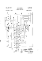
- FIG. 1 is a diagrammatic illustration of the washing ;machine of this invention showing the water supply apparatus for the washing machine; i
- the water filling apparatus for the washing machine includes a spout 22 having an outlet located over the top opening of tub 13. This spout is fed by a pipe 23 which is connected through solenoid valve apparatus to a hot water pipe 24 and a cold water pipe 25.
- the hot water pipe 24 and the cold water pipe 25 are connected with suitable hot and cold water supply means. These pipes are directly connected with a thermostatic mixing valve 27 of any well known construction, which mixes the hot and cold water to provide a water temperature that is intermediate the temperatures of the hot and cold water temperatures and which may be termed a warm tem- The warm Water exits from thermostatic mixing valve 27 into a pipe 28.
- the flow of water between pipes 24, 25 and 28 and pipe 23 is controlled by conventional solenoid operated valves 29, 30 and 31 which are normally closed and are operated to an open position by solenoids 32, 33 and 34.
- solenoid 32 When solenoid 32 is energized, hot water is supplied to the tub of the washing machine; When solenoid 33 is energized, warm water is supplied to the tub of the washing machine, and when solenoids 33 and 34 are both energized, water at a cool temperature is supplied to the tub of the washing machine.
- Fig. 2 a circuit diagram of the control circuit of the washing machine is shown.
- a sequential electrical controller or timer which includes an electric timer motor 35 that rotatably drives a shaft 36.
- the shaft 36 is connected with a control knob 37 which rotates with shaft 36.
- the control knob 37 and shaft 36 may also move axially to move an electric contactor 38 which cooperates with an electric contact to form a switch 39.
- the switch 39 is closed.
- the shaft 36 carries a plurality of cams designated, respectively, by reference numerals 40, 41, 42, 43 and 44. These cams, respectively operate electrical conducting contactors 45, 46, 47, 48 and 49.
- the contactor 45 is associated with two electrical contacts to form electric switches 51 and 52.
- contactors 46, 4,7, 48 and 49 cooperate with associated 7 3 electric contacts to form switches 53, 54, 55, 56, 57 and 58.
- the cams 40, 41, 42, 43 and 44 are designed to close the switches 51, '52, 53, 54, 55, 56, 57 and 58 during certain intervals of time, asindicated by' the chart in Fig. 3.
- timer motor '35 rotates shaft 36, the cams close the timer operated switches for predetermined intervals of time, as indicated by the chart in Fig. 3.
- the control circuit of Fig. 2 includes a selector switch generally designated by reference numeral 59, which controls the energization of solenoids 32, 33 and 34during the time when wash water is being supplied to the tub of the washing machine.
- This switch has a movable electrically conductive contactor 60 connected with a fixed contact or terminal 61.
- the contactor 60 is connected with an arcuate conductor portion 62 which selectively engages contacts 63, 64' and 65; When the movable contactor 60 is in the extreme -counter-clockwise position the contacts 61, 63- and 64 are connected together, whereas when the contactor 61 is in a vertical position, the contacts 61 and 64 are connected together. When the contactor 60 is in an extreme clockwise position, the contacts 61 and 65 are connected together.
- a similar selector switch generally designated by reference numeral 66 controls the energization of solenoids 32, 33 and 34 during the time rinse water is being supplied to the tub of the washing. machine.
- This switch includes fixed contacts 67, 68 and 69' and a movable elect-rical conductive contactor 70. When the movable contactor 70 is in the extreme counter-clockwise position the contacts 67 and 69 are connectedtogether and when the contactor 70 is in the extreme clockwise position, the contacts 68 and 69 are connected together. With the contactor 70 in a vertical position, the contacts 67, 68 and 69 are connected together.
- the electric motor 15 has one side connected directly to a power input line L and has its other side connected 7 with timer operated switch 57.
- the other power input line is designated by reference numeral L and the two power lines are connected with a suitable source of voltage.
- the movable contactor 49 is connected with a line 71 that is, in turn, connected with one side of.
- switch 56 The opposite side of switch 56 is connected to a line 72, that is in turn co'nnectedto a line 73 which leads to one side of switch 39.
- the opposite side of switch 39 is connected directly with power input line L
- the spin solenoid 17 has one side directly connected to line L and has its other side connected to one side of switch 52 via line 74.
- the opposite side ofswitch 52 is connected with a line 75 that is, in turn, connected with one side of switches 53 and 56.
- the opposite side of switch 53 is connected in series with lid operated switch 21 via a line 76. From an inspection of Figs. 2 and 3 it can be seen that the motor 15 is energized when switches 57, 56 and 39 are closed.
- the user of the washing machine desiring to set the machine into operation rotates the knob 3-7 to a start or wash-fill position and axially moves control shaft 36 to close switch 39.
- the switches 54, 56 and 58 are closed, as indicated by the sequence chart of Fig. 3 and the timer motor 35 is energized'to begin rotation of shaft 36.
- the wash selector swtitch 59 is in the position shown in-Fig. 2, the solenoids 34 and 33 are energized thereby providing the washing machine tub with water at a cool temperature.
- solenoid 33 in this position of the timer and selector switch 59 is energized. via line 79, switch '54, line 82,
- timer operatedswitch'58 When timer operatedswitch'58 opens, due to continued rotation of shaft 36, timer operated switch 57 closes to energize the electric motor 15, thereby vertically reciprocating agitator 14. Thisverticalreciprocation of agitator 14- agitates the clothes within tub 13 during the agitation cycle of the washing machine. Following the agitatmn cycle of the washing. machine, switches 52 andv 53 are closed .andswitch 56 opens to provide. anenergizing cirby the mixture of cold water and warm water frorn-pipes 25 and 28. The solenoid 33 is energized via l1ne 79,
- switch 55 line 83-, rinse selector.
- switch '66,v line 81, switch 51, switch 56 a and throughzswitch-39 to hne L -The'solenoid 34- is energized via line 84, rinse selector switch 66 Line 81', switch 51, switch 56and'through line switch 39 -to' line L If the movable contactor otrmse selector 66 were at this time. in the extreme counterclockwise position, only cold water would besupphed to the tub 13, as in this position only the soleno1d34 1s energized.
- solenoid 33 would be The solenoids32, 33 :,and34 that-operatevalves 29, 3i) energized to supply warm. waterfrom PiP to'the tub 13 of the washing machine. It thus can be seen that therinse selector switch 66 may be set at three difierent positions to provide for three ninse water temperatures for the washing machine.
- the wash selector switch 59 is connected with the solenoids 32, 33 and 34 during various settings of the switch by the timer perated switches 54, 56 and 58.
- the rinse selector switch 66 is at other times connected in circuit relationship with solenoids 32, 33 and 34 by timer operated switches 51, 55 and 56 for the various positions of the rinse selector switch.
- the wash selector switch 9 has exclusive control over the solenoids during the time the washing machine is being filled with wash water
- the rinse selector switch has exclusive control over the solenoids during the time the washing machine is being supplied with rinse water.
- the solenoid 32 is energized to provide hot water during the supplying of wash water to the washing machine.
- This circuit may be traced via line 78, through solenoid 32, through selector switch 59 via line 80, switch 58, switch 56, line 72, line 73, and back through line switch 39 to line L
- the rinse selector switch 66 is in an extreme counter-clockwise position so as to energize solenoid 34, cold water will be supplied to the washing machine during the rinse cycle.
- This circuit may be traced via line 78, through cold solenoid 34, via line 84, through rinse selector switch 66, through line 81, through switch 51, through switch 56, line 72, line 73, and via line 39 back to power input line L It can be seen that setting of the selector switch to provide hot water to the washing machine in no way aflEects the control by the rinse selector switch which was set to provide cold water during the rinse cycle of the washing machine. The same is true of the other settings of switches 59 and 60, and the switchm 59 and 66 thus have separate control over the solenoids during all settings of the switches.
- the switch 57 is closed, as indicated from the chart of Fig. 3, to provide vertical reciprocation of agitator 14 during the supplying of rinse water to the tub.
- the switches 52 and 53 are closed to provide for high speed spinning of the tub, whereupon the rinse water is centrifugally thrown into outer tub 12 and is exhausted to drain.
- the cycle of the machine ends when the high speed spin cycle is completed and this occurs when switches 5-2 and 53 open for the second time, as shown in the chart of Fig. 3.
- a washing machine having a tub, conduit means for conducting water to said tub, a cold water inlet pipe, a hot water inlet pipe, a mixed water inlet pipe, a first solenoid operated valve including a first solenoid connected between said cold water inlet pipe and said conduit means, a second solenoid operated valve including a second solenoid connected between said hot water inlet pipe and said conduit means, a third solenoid operated valve including a third solenoid connected between said mixed water inlet pipe and said conduit means, a timer, first, second, third and fourth timer operated switches periodically closed by said timer with said first and third switches being both closed during a certain periodof time and said second and fourth switches both being closed during a second ditferent period of time, an input power lead directly connected to one side of all of said solenoids, a wash selector switch having a first terminal connected with a movable contactor and having second, third and fourth terminals, said contactor having a first position wherein said first terminal is connected with said second and third and fourth
Description
Oct. 18, 1960 Filed June 27. 1957 K. O. SISSON DOMESTIC APPLIANCE 2 Sheets-Sheet 1 TIME III MINUTES [2 I8 26 30 56 42 INVENTOR.
/1 amid)! O. Sisson HIS ATTORNEY 0&. 18, 1960 Filed June 27, 1957 K. O. SISSON DOMESTIC APPLIANCE 2 Sheets-Sheet 2 HISATTORNEY DOMESTIC APPLIANCE Kenneth 0. Sisson, Dayton, Ohio, assignor to General Motors Corporation, Detroit, Mich., a corporation of Delaware Filed June 27, 1957, Ser. No. 668,484
1 Claim. (CI. 6812) This invention relates to a domestic appliance and more particularly to a water temperature control system for controlling the temperature of water being supplied to the tub of a washing machine. My copending application Serial No. 668,485 filed June 27, 1957, relates to another water control system for a washing machine. An object of the invention is to provide a washing machine with solenoid operated valve apparatus that operates to control the temperature of water being supplied to the tub of the machine, the control apparatus including a wash selector switch and a rinse selector 'switch both connected wtih a voltage supply and with the solenoid valve apparatus for controlling the temperature of both the wash water and rinse water that is supplied to the tub of the machine, and wherein the wash selector switch and the rinse selector switch may be preset prior to a washing operation.
Another object of this invention is to provide a water temperature control system for a washing machine which includes a solenoid operated valve, a rinse selector switch, 'a wash selector switch, and a timer operated switch mecha nism all connected with a voltage supply, and wherein the timer operated switch mechanism alternately places the solenoid valve either under control of the wash selector switch or under control of the rinse selector switch. A further object of this invention is to provide a water temperature control system for a washing machine which includes a plurality of solenoid operated valves that control the passage of water between a plurality of the water inlet pipes and the tub of the machine, the system including a wash selector switch connected with the solenoids for controlling the passage of wash water into the tub, and a rinse selector switch connected with the solenoids :for controlling the passage of rinse water into the tub, "each switch having a plurality of temperature settings, lthere being switch means in the circuit for alternately :placing either the wash selector switch or the rinse selector switch in sole control of the solenoid operated valves.
Still another object of this invention is to provide a" 1 water temperature control system for a washing machine which includes, a plurality of solenoid operated valves 'thatcontrol the passage of water between a plurality of water inlet pipes and the tub of the machine, the system 7 including a wash selector switch for controlling the solenoid valves and a rinse selector switch for controlling the solenoid valves, there being a timer operated switch mechanism for alternately directly connecting the sole- "noids of the valves in a circuit with the rinse selector switch or wash selector switch without the use of relays ,or other similar auxiliary circuit apparatus. Further objects and advantages of the present invention will be apparent from the following description, reference being had to the accompanying drawings, wherein a preferred form of the present invention is clearly shown. 7 In the drawings:
Figure 1 is a diagrammatic illustration of the washing ;machine of this invention showing the water supply apparatus for the washing machine; i
' perature.
2,956,426 Patented Oct. 18, 1960 motor 15 through a transmission 16. A spin solenoid 17 controls the transmission so as to provide for either vertical reciprocation of agitator 14 or high speed rotation of tub 13. When the electric motor 15 is energized the agitator 14 is vertically reciprocated and when the motor 15 and spin solenoid 17 are both energized, the tub 13 is rotated at high speed for spinning water out of the inner tub 13 into the outer tub 12. The transmission mechanism and spin solenoid may be of the type shown in the patent to Kendall Clark, 2,422,395, dated June 17, 1947. The'outer tub 12 is exhausted of water by a pump 18 that is driven by electric motor 15 and which 'is connected to the tub 12 by pipe 19. The top of the washing machine has an access opening that is closed by a'door 20 which is pivoted to the outer cabinet of the machine. The door actuates a normally open door switch 21 to its closed position when the door is in a closed position.
'The water filling apparatus for the washing machine includes a spout 22 having an outlet located over the top opening of tub 13. This spout is fed by a pipe 23 which is connected through solenoid valve apparatus to a hot water pipe 24 and a cold water pipe 25. The pipes 23,
24 and 25 and the solenoid valve apparatus are preferably located within the washing machine but are shown exteriorly thereof for clarity of explanation. The hot water pipe 24 and the cold water pipe 25 are connected with suitable hot and cold water supply means. These pipes are directly connected with a thermostatic mixing valve 27 of any well known construction, which mixes the hot and cold water to provide a water temperature that is intermediate the temperatures of the hot and cold water temperatures and which may be termed a warm tem- The warm Water exits from thermostatic mixing valve 27 into a pipe 28. The flow of water between pipes 24, 25 and 28 and pipe 23 is controlled by conventional solenoid operated valves 29, 30 and 31 which are normally closed and are operated to an open position by solenoids 32, 33 and 34. When solenoid 32 is energized, hot water is supplied to the tub of the washing machine; When solenoid 33 is energized, warm water is supplied to the tub of the washing machine, and when solenoids 33 and 34 are both energized, water at a cool temperature is supplied to the tub of the washing machine.
Referring now to Fig. 2, a circuit diagram of the control circuit of the washing machine is shown. The
various operations of the washing machine are controlled by a sequential electrical controller or timer which includes an electric timer motor 35 that rotatably drives a shaft 36. The shaft 36 is connected with a control knob 37 which rotates with shaft 36. The control knob 37 and shaft 36 may also move axially to move an electric contactor 38 which cooperates with an electric contact to form a switch 39. When the shaft 36 is pushed in so as to move it rightwardly in Fig. 2, the switch 39 is closed. The shaft 36 carries a plurality of cams designated, respectively, by reference numerals 40, 41, 42, 43 and 44. These cams, respectively operate electrical conducting contactors 45, 46, 47, 48 and 49. The contactor 45 is associated with two electrical contacts to form electric switches 51 and 52. In a like manner contactors 46, 4,7, 48 and 49 cooperate with associated 7 3 electric contacts to form switches 53, 54, 55, 56, 57 and 58. The cams 40, 41, 42, 43 and 44 are designed to close the switches 51, '52, 53, 54, 55, 56, 57 and 58 during certain intervals of time, asindicated by' the chart in Fig. 3. Thus, as timer motor '35 rotates shaft 36, the cams close the timer operated switches for predetermined intervals of time, as indicated by the chart in Fig. 3.
The control circuit of Fig. 2 includes a selector switch generally designated by reference numeral 59, which controls the energization of solenoids 32, 33 and 34during the time when wash water is being supplied to the tub of the washing machine. This switch has a movable electrically conductive contactor 60 connected with a fixed contact or terminal 61. The contactor 60 is connected with an arcuate conductor portion 62 which selectively engages contacts 63, 64' and 65; When the movable contactor 60 is in the extreme -counter-clockwise position the contacts 61, 63- and 64 are connected together, whereas when the contactor 61 is in a vertical position, the contacts 61 and 64 are connected together. When the contactor 60 is in an extreme clockwise position, the contacts 61 and 65 are connected together.
A similar selector switch generally designated by reference numeral 66 controls the energization of solenoids 32, 33 and 34 during the time rinse water is being supplied to the tub of the washing. machine. This switch includes fixed contacts 67, 68 and 69' and a movable elect-rical conductive contactor 70. When the movable contactor 70 is in the extreme counter-clockwise position the contacts 67 and 69 are connectedtogether and when the contactor 70 is in the extreme clockwise position, the contacts 68 and 69 are connected together. With the contactor 70 in a vertical position, the contacts 67, 68 and 69 are connected together.
The electric motor 15 has one side connected directly to a power input line L and has its other side connected 7 with timer operated switch 57. The other power input line is designated by reference numeral L and the two power lines are connected with a suitable source of voltage. The movable contactor 49 is connected with a line 71 that is, in turn, connected with one side of.
and 31 are connected together at a common tie-point 77. This common tie-point is connected directly to input power line L via line 78. The opposite side of solenoid 32 is connected directly with switch contact 65. The opposite side of solenoid 34 is connected directly with contact 63 of switch 59 and with contact 67 of switch 66. The solenoid 33 is connected to movable contactor 47 via line 79. The terminal 6-1 of switch 59 is connected to oneside of switch 58 via line 80. W The fixed contact 69 of switch'66' is-conncctedto one side of switch 51 via line 81. The fixed contact 64 of switch 59 is connectedto one side of switch 54 via line 82. The fixed terminal 68 of switch 66is directly connected to one side of switch 55 via line 83. j
The user of the washing machine desiring to set the machine into operation rotates the knob 3-7 to a start or wash-fill position and axially moves control shaft 36 to close switch 39. In this position the switches 54, 56 and 58 are closed, as indicated by the sequence chart of Fig. 3 and the timer motor 35 is energized'to begin rotation of shaft 36. Assuming that the wash selector swtitch 59 is in the position shown in-Fig. 2, the solenoids 34 and 33 are energized thereby providing the washing machine tub with water at a cool temperature. The
switch 59, line 80, switch 58, switch 56, and line switch 39. The solenoid 34 is energized via line 83, selector switch 59, switch 58, switch 56, and through line switch 39. In this position of wash selector switch 59 wash'water at a cool temperature is supplied to tub 13 due to the fact that warm water andcold water from lines- 28 and 25, respectively, are being-mixed and supplied to the tub 13. If the selector switch 59 were in its vertical intermediate position at this time, only warm water would be supplied to tub 13 as only the solenoid 3- 3 would be energized, as is apparent t'rom'the circuit of Fig. 3.- If the selector switch were in the extreme clockwise position so as to connect contacts 61' and 65, only solenoid 32 would be energized to supply hot water only to the till) 13. The tub continues to fill with water as long as timer operated switches 54, 56 andv 58'areclosed, and when switch 58 opensthe wash-fill cycle of the washing machine is ended.
When timer operatedswitch'58 opens, due to continued rotation of shaft 36, timer operated switch 57 closes to energize the electric motor 15, thereby vertically reciprocating agitator 14. Thisverticalreciprocation of agitator 14- agitates the clothes within tub 13 during the agitation cycle of the washing machine. Following the agitatmn cycle of the washing. machine, switches 52 andv 53 are closed .andswitch 56 opens to provide. anenergizing cirby the mixture of cold water and warm water frorn- pipes 25 and 28. The solenoid 33 is energized via l1ne 79,
switch 55, line 83-, rinse selector. switch '66,v line 81, switch 51, switch 56 a and throughzswitch-39 to hne L -The'solenoid 34- is energized via line 84, rinse selector switch 66 Line 81', switch 51, switch 56and'through line switch 39 -to' line L If the movable contactor otrmse selector 66 were at this time. in the extreme counterclockwise position, only cold water would besupphed to the tub 13, as in this position only the soleno1d34 1s energized. If the rinse selector switch-wereatrthis time in the extreme clockwise position, only, solenoid 33would be The solenoids32, 33 :,and34 that-operatevalves 29, 3i) energized to supply warm. waterfrom PiP to'the tub 13 of the washing machine. It thus can be seen that therinse selector switch 66 may be set at three difierent positions to provide for three ninse water temperatures for the washing machine.
It can be seen from the foregoing that the wash selector switch 59 is connected with the solenoids 32, 33 and 34 during various settings of the switch by the timer perated switches 54, 56 and 58. On the other hand, the rinse selector switch 66 is at other times connected in circuit relationship with solenoids 32, 33 and 34 by timer operated switches 51, 55 and 56 for the various positions of the rinse selector switch. With such an arrangement the wash selector switch 9 has exclusive control over the solenoids during the time the washing machine is being filled with wash water, and the rinse selector switch has exclusive control over the solenoids during the time the washing machine is being supplied with rinse water. Thus, assuming that the wash selector switch 59 is in a fully clockwise position to connect contacts 61 and 65-, the solenoid 32 is energized to provide hot water during the supplying of wash water to the washing machine. This circuit may be traced via line 78, through solenoid 32, through selector switch 59 via line 80, switch 58, switch 56, line 72, line 73, and back through line switch 39 to line L If at the same time the rinse selector switch 66 is in an extreme counter-clockwise position so as to energize solenoid 34, cold water will be supplied to the washing machine during the rinse cycle. This circuit may be traced via line 78, through cold solenoid 34, via line 84, through rinse selector switch 66, through line 81, through switch 51, through switch 56, line 72, line 73, and via line 39 back to power input line L It can be seen that setting of the selector switch to provide hot water to the washing machine in no way aflEects the control by the rinse selector switch which was set to provide cold water during the rinse cycle of the washing machine. The same is true of the other settings of switches 59 and 60, and the switchm 59 and 66 thus have separate control over the solenoids during all settings of the switches.
At some point very near the end of the rinse-fill cycle of the washing machine the switch 57 is closed, as indicated from the chart of Fig. 3, to provide vertical reciprocation of agitator 14 during the supplying of rinse water to the tub. After the rinse cycle is completed, the switches 52 and 53 are closed to provide for high speed spinning of the tub, whereupon the rinse water is centrifugally thrown into outer tub 12 and is exhausted to drain. The cycle of the machine ends when the high speed spin cycle is completed and this occurs when switches 5-2 and 53 open for the second time, as shown in the chart of Fig. 3.
While the form of embodiment of the invention as herein disclosed constitutes a preferred form, it is to be understood that other forms might be adopted, as may come within the scope of the claim which follows.
What is claimed is as follows:
In combination with a washing machine having a tub, conduit means for conducting water to said tub, a cold water inlet pipe, a hot water inlet pipe, a mixed water inlet pipe, a first solenoid operated valve including a first solenoid connected between said cold water inlet pipe and said conduit means, a second solenoid operated valve including a second solenoid connected between said hot water inlet pipe and said conduit means, a third solenoid operated valve including a third solenoid connected between said mixed water inlet pipe and said conduit means, a timer, first, second, third and fourth timer operated switches periodically closed by said timer with said first and third switches being both closed during a certain periodof time and said second and fourth switches both being closed during a second ditferent period of time, an input power lead directly connected to one side of all of said solenoids, a wash selector switch having a first terminal connected with a movable contactor and having second, third and fourth terminals, said contactor having a first position wherein said first terminal is connected with said second and third terminals, a second position wherein said first terminal is connected with said third terminal and a third position wherein said first terminal is connected with said fourth terminal, a rinse selector switch having a first terminal connected with a movable contactor and having second and third terminals, said rinse switch contactor having a first position wherein said first terminal is connected with said second and third terminals, a second position wherein said first terminal is connected with said second terminal and a third position wherein said first terminal is connected with said third terminal, means directly connecting an opposite side of said first solenoid with said second terminal of said wash selector switch and with said second terminal of said rinse selector switch, means directly connecting an opposite side of said second solenoid with the fourth terminal of said wash selector switch, means directly connecting the opposite side of said third solenoid with one side of said second and third timer operated switches, means connecting the third terminal of said wash selector switch to an opposite side of said second timer operated switch, means connecting the third terminal of said rinse selector switch to an opposite side of said third timer operated switch, means connecting the first terminal of said wash selector switch to one side of said fourth timer operated switch, means connecting the first terminal of said rinse selector switch with one side of said first timer operated switch, and a second power supply lead connected to the opposite side of said first and fourth timer operated switches.
References Cited in the file of this patent UNITED STATES PATENTS 2,503,901 Chace Apr. 11, 1950 2,561,348 Dunham July 24, 1951 2,636,372 Rand Apr. 28, 1953 2,662,384 Morrison Dec. 15, 1953 2,752,769 Clark July 3, 1956 2,841,003 Conlee July 1, 1958 2,858,687 Clark V.. Nov, 4, 1958
Priority Applications (1)
| Application Number | Priority Date | Filing Date | Title |
|---|---|---|---|
| US668484A US2956426A (en) | 1957-06-27 | 1957-06-27 | Domestic appliance |
Applications Claiming Priority (1)
| Application Number | Priority Date | Filing Date | Title |
|---|---|---|---|
| US668484A US2956426A (en) | 1957-06-27 | 1957-06-27 | Domestic appliance |
Publications (1)
| Publication Number | Publication Date |
|---|---|
| US2956426A true US2956426A (en) | 1960-10-18 |
Family
ID=24682481
Family Applications (1)
| Application Number | Title | Priority Date | Filing Date |
|---|---|---|---|
| US668484A Expired - Lifetime US2956426A (en) | 1957-06-27 | 1957-06-27 | Domestic appliance |
Country Status (1)
| Country | Link |
|---|---|
| US (1) | US2956426A (en) |
Cited By (2)
| Publication number | Priority date | Publication date | Assignee | Title |
|---|---|---|---|---|
| WO2004106617A1 (en) * | 2003-05-28 | 2004-12-09 | Electrolux Home Products Corporation N.V. | Clothes washing machine with an integrated arrangement of electromagnetic valves |
| US20110041561A1 (en) * | 2009-08-23 | 2011-02-24 | Adam Apel | Apparatus And Method For Supplying Hot, Cold Or Mixed Water To A Washing Machine Using A Single Water Supply Hose |
Citations (7)
| Publication number | Priority date | Publication date | Assignee | Title |
|---|---|---|---|---|
| US2503901A (en) * | 1943-12-09 | 1950-04-11 | Dole Valve Co | Fluid control system particularly for use with automatic clotheswashing machines |
| US2561348A (en) * | 1947-02-20 | 1951-07-24 | George W Dunham | Automatic timer for washing machines and the like |
| US2636372A (en) * | 1948-01-31 | 1953-04-28 | H J Rand Washing Machine Corp | Automatic washing machine |
| US2662384A (en) * | 1947-06-28 | 1953-12-15 | Whirlpool Co | Washing machine control mechanism |
| US2752769A (en) * | 1952-11-14 | 1956-07-03 | Gen Electric | Control circuits for automatic washing machines |
| US2841003A (en) * | 1955-01-17 | 1958-07-01 | Gen Electric | Control circuits for automatic clothes washing machines |
| US2858687A (en) * | 1954-09-20 | 1958-11-04 | Gen Electric | Control circuits for automatic clothes washing machines |
-
1957
- 1957-06-27 US US668484A patent/US2956426A/en not_active Expired - Lifetime
Patent Citations (7)
| Publication number | Priority date | Publication date | Assignee | Title |
|---|---|---|---|---|
| US2503901A (en) * | 1943-12-09 | 1950-04-11 | Dole Valve Co | Fluid control system particularly for use with automatic clotheswashing machines |
| US2561348A (en) * | 1947-02-20 | 1951-07-24 | George W Dunham | Automatic timer for washing machines and the like |
| US2662384A (en) * | 1947-06-28 | 1953-12-15 | Whirlpool Co | Washing machine control mechanism |
| US2636372A (en) * | 1948-01-31 | 1953-04-28 | H J Rand Washing Machine Corp | Automatic washing machine |
| US2752769A (en) * | 1952-11-14 | 1956-07-03 | Gen Electric | Control circuits for automatic washing machines |
| US2858687A (en) * | 1954-09-20 | 1958-11-04 | Gen Electric | Control circuits for automatic clothes washing machines |
| US2841003A (en) * | 1955-01-17 | 1958-07-01 | Gen Electric | Control circuits for automatic clothes washing machines |
Cited By (4)
| Publication number | Priority date | Publication date | Assignee | Title |
|---|---|---|---|---|
| WO2004106617A1 (en) * | 2003-05-28 | 2004-12-09 | Electrolux Home Products Corporation N.V. | Clothes washing machine with an integrated arrangement of electromagnetic valves |
| US20070220927A1 (en) * | 2003-05-28 | 2007-09-27 | Electrolux Home Products Corporation N.V. | Clothes Washing Machine with an Integrated Arrangement of Electromagnetic Valves |
| US7650765B2 (en) | 2003-05-28 | 2010-01-26 | Electrolux Home Products Corporation N.V. | Clothes washing machine with an integrated arrangement of electromagnetic valves |
| US20110041561A1 (en) * | 2009-08-23 | 2011-02-24 | Adam Apel | Apparatus And Method For Supplying Hot, Cold Or Mixed Water To A Washing Machine Using A Single Water Supply Hose |
Similar Documents
| Publication | Publication Date | Title |
|---|---|---|
| US3662186A (en) | Electronic control circuit for appliances | |
| US2561348A (en) | Automatic timer for washing machines and the like | |
| US2579598A (en) | Control for automatic washing machines | |
| US2608252A (en) | Domestic appliance | |
| US2662384A (en) | Washing machine control mechanism | |
| US3477258A (en) | Total sensing automatic washer | |
| US2447848A (en) | Cleaning and centrifuging apparatus | |
| US2425788A (en) | Laundry apparatus | |
| US2956426A (en) | Domestic appliance | |
| US2502823A (en) | Control switch means for clotheswashing machines | |
| US3648487A (en) | Washer load sensor control | |
| US2949759A (en) | Domestic appliance | |
| US3171045A (en) | Timer | |
| US3128615A (en) | Automatic washing machine having a two-speed electric motor | |
| US2426078A (en) | Washing machine transmission | |
| US2520695A (en) | Automatic sequential operation type clothes washing machine | |
| US2376901A (en) | Timing control | |
| US2554566A (en) | Fluid control means for automatic cleansing apparatus | |
| US3134385A (en) | Article washing and drying machine having reversing single-phase induction motor | |
| US2748585A (en) | Domestic appliance | |
| GB1089217A (en) | Control device for a washing machine | |
| US3344625A (en) | Plural level fill system for washer apparatus | |
| US3552156A (en) | Washing and spin-drying machine | |
| US1639368A (en) | Automatic washing machine | |
| US2477415A (en) | Water control mechanism for automatic washing machines |