US294635A - Extensible fire-escape - Google Patents
Extensible fire-escape Download PDFInfo
- Publication number
- US294635A US294635A US294635DA US294635A US 294635 A US294635 A US 294635A US 294635D A US294635D A US 294635DA US 294635 A US294635 A US 294635A
- Authority
- US
- United States
- Prior art keywords
- scaffold
- frame
- escape
- windlass
- extensible
- Prior art date
- Legal status (The legal status is an assumption and is not a legal conclusion. Google has not performed a legal analysis and makes no representation as to the accuracy of the status listed.)
- Expired - Lifetime
Links
- 230000000153 supplemental effect Effects 0.000 description 3
- 238000010276 construction Methods 0.000 description 1
- 238000004804 winding Methods 0.000 description 1
Images

Classifications
-
- E—FIXED CONSTRUCTIONS
- E06—DOORS, WINDOWS, SHUTTERS, OR ROLLER BLINDS IN GENERAL; LADDERS
- E06C—LADDERS
- E06C5/00—Ladders characterised by being mounted on undercarriages or vehicles Securing ladders on vehicles
- E06C5/02—Ladders characterised by being mounted on undercarriages or vehicles Securing ladders on vehicles with rigid longitudinal members
- E06C5/04—Ladders characterised by being mounted on undercarriages or vehicles Securing ladders on vehicles with rigid longitudinal members capable of being elevated or extended ; Fastening means during transport, e.g. mechanical, hydraulic
Definitions
- the invention consists of the novel construction and arrangement of parts hereinafter described aud claimed.
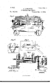
- Figure 1 is a side elevation of my improved extensible fire-escape and scafiold, partly in section.
- Fig. 2 is an end elevation of the same, showing the supportingframe in section on line 00 x of Fig. 1.
- Fig. 3 is a side elevation of the invention, showing the scaffold folded.
- Fig. 4 is a detail view of the guide-rope Windlass.
- Fig. 5 is an end view of the supporting-frame, showing the cam-sup ported brace or prop.
- Fig. 6 is a detail vertical section; and Fig. 7, a detail horizontal section, showing the means for inclining the scaffold to one side.
- A indicates the fire-escape or scaffold, and 13 its wheeled supporting-frame.
- the former consists of four series of. lazy-tongs arranged in pairs CD, which are connected together by the links E in such manner as to form a central open space, F, between the connectinglinks E at the sides and the pivotal rods G at the ends of the scaffold.
- the bottom of the scaffold is pivoted by means of the inner arms or bars, H, upon the two rods I, which are firmly supported in fixed bearings in the sides of the supplemental frame B, and the .outer bars, J, which are pivoted to the centers of the bars H, are adapted to slide on the segmental supports K in the adjustment of the scaffold.
- the lower ends of the bars J are provided with inwardly-extending elbows L, which are connected in .pairs by the rods M, and are adapted to be drawn inward to extend the scaffold by means of the Windlass N and the cords 0, connected to the'sleeves P on the said rods.
- the cords Q which are connected to the sleeves Band passed around pulleys R in the ends of frame B when it is desired to lower the scaffold or fold it for transportation.
- the windlass is provided with a pawl and ratchet to hold it at any clesi red position, and the links E are provided with stops S, against which the pivoted braces T will bear when the scaffold is raised to its highest extent, and thus render the entire frame-work rigid and compact.
- A the lower ends of which are wound on a Windlass, B which is adapted to tighten the ropes at any elevation of the scaffold.
- These ropes are guides for the basket 0, which is loosely connected thereto and adapted to be raised and lowered by a cord, D, passing over a pulley, E, and wind ing on a Windlass, F, supported on the frame B.
- a ladder, G may also be suspended from.
- the top of the scaffold and adapted to be wound on a windlass as the scaffold is lowered.
- This windlass N with its joint J, may also serve as a connection between the frames B B, to prevent said frames frombeing displaced with. respect to each other 5
- a cam-lever, O pivoted to frame B, is then turned down against the upper surface of the prop to hold it firmly against the ground.
- Vhen the props are in the guides N, they may be secured therein by catches P, pivoted to frame B and adapted to engage the same.
- the wheeled frame B is intended to be lowered at one end 011 inclined ground, to support the base of the scaffold on a level.
- the axle Q is supported in arms R, which are adjustable vertically by means of the screws S in the frame B.
- T T are slotted guides for the axle, and U is the brake-rod.
- W'hat I claim is 1.
Description
(No Model.) 3 sheets -sheet 1.
P. KINGSTON.
EXTENSIBLE .FIRE ESCAPE.
Patented Mar. 4, 1884.
l O M. N 4
ATTORNEYS. V
(No Model.) 3 Sheets-Sheet 2.
' P. KINGSTON.
EXTENSIBLE FIRE ESCAPE.
Patented Mar. 4, 1884;
WITNESSES ATTORNEYS.
( Model.) .3 Sheets-$114391; 3.
- P, KINGSTON.
EXTENSIBLE FIR-E ESCAPE.
Patented Mar. 4, 1884.
mmmmmmlllmnl ATTORNEYS.
n. PETERS. PIwlo-bthugnphur, Wnhinglcm n. c,
NITED STATES PATENT FFIGEe PAUL KINGSTOLK O'F HASTINGS, MINNESOTA.
EXTENSI BLE Fl RE-ESCAPE.
SPECIFICATION forming part'of Letters Patent No. 29%,635, dated March 4, 1884, Application filed May 5, 1883. (No model.)
To all whom it may concern:
Be it known that I, PAUL KINGSTON, of Hastings, in the county of Dakota and State of Minnesota, have invented a new and useful Improvement in Extensible Fire-Escapes andcapes and scaffolds which are formed of extensible parts,to adapt them for use at any desired elevation, and to enable them to be folded compactly when not in use.
The invention consists of the novel construction and arrangement of parts hereinafter described aud claimed.
In the drawings, Figure 1 is a side elevation of my improved extensible fire-escape and scafiold, partly in section. Fig. 2 is an end elevation of the same, showing the supportingframe in section on line 00 x of Fig. 1. Fig. 3 is a side elevation of the invention, showing the scaffold folded. Fig. 4 is a detail view of the guide-rope Windlass. Fig. 5 is an end view of the supporting-frame, showing the cam-sup ported brace or prop. Fig. 6 is a detail vertical section; and Fig. 7, a detail horizontal section, showing the means for inclining the scaffold to one side.
A indicates the fire-escape or scaffold, and 13 its wheeled supporting-frame. The former consists of four series of. lazy-tongs arranged in pairs CD, which are connected together by the links E in such manner as to form a central open space, F, between the connectinglinks E at the sides and the pivotal rods G at the ends of the scaffold. The bottom of the scaffold is pivoted by means of the inner arms or bars, H, upon the two rods I, which are firmly supported in fixed bearings in the sides of the supplemental frame B, and the .outer bars, J, which are pivoted to the centers of the bars H, are adapted to slide on the segmental supports K in the adjustment of the scaffold. The lower ends of the bars J are provided with inwardly-extending elbows L, which are connected in .pairs by the rods M, and are adapted to be drawn inward to extend the scaffold by means of the Windlass N and the cords 0, connected to the'sleeves P on the said rods. On the same windlass are to be wound the cords Q, which are connected to the sleeves Band passed around pulleys R in the ends of frame B when it is desired to lower the scaffold or fold it for transportation. The windlass is provided with a pawl and ratchet to hold it at any clesi red position, and the links E are provided with stops S, against which the pivoted braces T will bear when the scaffold is raised to its highest extent, and thus render the entire frame-work rigid and compact.
To the upper and innermost cross-rods, G,
are secured two ropes, A, the lower ends of which are wound on a Windlass, B which is adapted to tighten the ropes at any elevation of the scaffold. These ropes are guides for the basket 0, which is loosely connected thereto and adapted to be raised and lowered by a cord, D, passing over a pulley, E, and wind ing on a Windlass, F, supported on the frame B. A ladder, G, may also be suspended from.
the top of the scaffold, and adapted to be wound on a windlass as the scaffold is lowered.
"To adapt the fire-escape and scaffoldto be inclined to one side in case the wheeled supporting-frame cannot be placed close to the wall of a house, I adapt the supplemental frame B to be lowered at one side by means of a vertical supporting-screw, H, to vwhich the said frame is connected. This screw is to be operated by a hand-wheel, I. The side of the frame B which is not to be lowered I is to be supported loosely on any suitable support or ledge attached to the stationary frame B 5 or it 8 5 may be flexibly connected thereto inany suitable manner. The shaft of the Windlass N is provided with a universal joint, J, to allow one part of it to be inclined with the scaffold,
while the other part, which is supported in 0 one side of the supporting-frame B, shall remain stationary. This windlass N, with its joint J, may also serve as a connection between the frames B B, to prevent said frames frombeing displaced with. respect to each other 5 As a means of still further brac- IOO end on the ground. A cam-lever, O, pivoted to frame B, is then turned down against the upper surface of the prop to hold it firmly against the ground.
Vhen the props are in the guides N, they may be secured therein by catches P, pivoted to frame B and adapted to engage the same.
The wheeled frame B is intended to be lowered at one end 011 inclined ground, to support the base of the scaffold on a level. For this purpose the axle Q is supported in arms R, which are adjustable vertically by means of the screws S in the frame B. T T are slotted guides for the axle, and U is the brake-rod.
W'hat I claim is 1. The combination of the series of lazytongs arranged in pairs connected by crossrods, and the connecting-links E, having stops thereon, and the braces T, adapted to engage with the stops when the device is extended, whereby the same may be rendered rigid and firm, substantially as shown and described.
2. The combination, with the lazy-tongs having the inner cross-bars, H, pivoted 011 stationary rods I, and the segmental supports K, the 25 outer cross-bars, J, having elbows L, and the rods M, sleeves P, cords O Q, pulleys R, and Windlass N, substantially as shown and described.
3. The co1nbination,with the extensible fire 30 escape, of the guide-ropes A, adapted to be adjusted and held byawindlass to correspond to the desired height of the scaffold, and the basketO,connected totheropesA,andadapted to be raised or lowered by the cord D, sub- 35 stantially as shown and described.
4. The combination, with the supportingframe B and the scaffold A, of the supplemental frame 13, adapted to be lowered at one side to incline the scaffold, and the windlass- 4o operated stay-cords K and cam-supported props M, substantially as shown and described.
PAUL KINGSTON.
Vitnesses:
A. G. LYNE,, SoLoN C. Kmrox.
Publications (1)
| Publication Number | Publication Date |
|---|---|
| US294635A true US294635A (en) | 1884-03-04 |
Family
ID=2363822
Family Applications (1)
| Application Number | Title | Priority Date | Filing Date |
|---|---|---|---|
| US294635D Expired - Lifetime US294635A (en) | Extensible fire-escape |
Country Status (1)
| Country | Link |
|---|---|
| US (1) | US294635A (en) |
-
0
- US US294635D patent/US294635A/en not_active Expired - Lifetime
Similar Documents
| Publication | Publication Date | Title |
|---|---|---|
| US107225A (en) | Improvement in adjustable lifting-ladder | |
| US936681A (en) | Ladder. | |
| US483001A (en) | Combined water-tower and fire-escape | |
| US202426A (en) | Improvement in extension-ladders | |
| US440827A (en) | Fire-escape tower | |
| US294635A (en) | Extensible fire-escape | |
| US459613A (en) | Nelson newman | |
| US295269A (en) | miller | |
| US581197A (en) | Fire-escape | |
| US1003967A (en) | Combined water-tower and fire-escape. | |
| US197324A (en) | Improvement in firemen s lad | |
| US1025972A (en) | Portable fire-escape. | |
| US837006A (en) | Portable scaffold. | |
| US204893A (en) | Improvement in fire-escape ladders | |
| US800806A (en) | Adjustable scaffold. | |
| US346406A (en) | hutceings | |
| US836868A (en) | Fire-escape. | |
| US396175A (en) | Fire-escape | |
| US232968A (en) | hofele | |
| US268608A (en) | Fire-escape | |
| US283650A (en) | Madison m | |
| US285273A (en) | Fire-escape ladder | |
| US291378A (en) | Fire-escape | |
| US394625A (en) | wells | |
| US264577A (en) | Smith |