US2944629A - Tobacco separating apparatus - Google Patents
Tobacco separating apparatus Download PDFInfo
- Publication number
- US2944629A US2944629A US677314A US67731457A US2944629A US 2944629 A US2944629 A US 2944629A US 677314 A US677314 A US 677314A US 67731457 A US67731457 A US 67731457A US 2944629 A US2944629 A US 2944629A
- Authority
- US
- United States
- Prior art keywords
- ducts
- air
- tobacco
- dust
- air stream
- Prior art date
- Legal status (The legal status is an assumption and is not a legal conclusion. Google has not performed a legal analysis and makes no representation as to the accuracy of the status listed.)
- Expired - Lifetime
Links
- 235000002637 Nicotiana tabacum Nutrition 0.000 title description 36
- 244000061176 Nicotiana tabacum Species 0.000 title 1
- 239000000428 dust Substances 0.000 description 36
- 241000208125 Nicotiana Species 0.000 description 35
- 239000000463 material Substances 0.000 description 7
- 239000002245 particle Substances 0.000 description 4
- 238000009825 accumulation Methods 0.000 description 3
- 210000001520 comb Anatomy 0.000 description 3
- 238000005096 rolling process Methods 0.000 description 3
- 210000003746 feather Anatomy 0.000 description 2
- 241000251169 Alopias vulpinus Species 0.000 description 1
- 235000019013 Viburnum opulus Nutrition 0.000 description 1
- 244000071378 Viburnum opulus Species 0.000 description 1
- 230000001133 acceleration Effects 0.000 description 1
- 238000010276 construction Methods 0.000 description 1
- 230000007423 decrease Effects 0.000 description 1
- 230000000694 effects Effects 0.000 description 1
- 230000008030 elimination Effects 0.000 description 1
- 238000003379 elimination reaction Methods 0.000 description 1
- 239000000203 mixture Substances 0.000 description 1
- 239000003208 petroleum Substances 0.000 description 1
- 230000003014 reinforcing effect Effects 0.000 description 1
- 239000004576 sand Substances 0.000 description 1
- 238000000926 separation method Methods 0.000 description 1
- 238000009987 spinning Methods 0.000 description 1
- 238000011144 upstream manufacturing Methods 0.000 description 1
Images

Classifications
-
- B—PERFORMING OPERATIONS; TRANSPORTING
- B04—CENTRIFUGAL APPARATUS OR MACHINES FOR CARRYING-OUT PHYSICAL OR CHEMICAL PROCESSES
- B04C—APPARATUS USING FREE VORTEX FLOW, e.g. CYCLONES
- B04C5/00—Apparatus in which the axial direction of the vortex is reversed
- B04C5/24—Multiple arrangement thereof
- B04C5/28—Multiple arrangement thereof for parallel flow
-
- A—HUMAN NECESSITIES
- A24—TOBACCO; CIGARS; CIGARETTES; SIMULATED SMOKING DEVICES; SMOKERS' REQUISITES
- A24B—MANUFACTURE OR PREPARATION OF TOBACCO FOR SMOKING OR CHEWING; TOBACCO; SNUFF
- A24B5/00—Stripping tobacco; Treatment of stems or ribs
- A24B5/10—Stripping tobacco; Treatment of stems or ribs by crushing the leaves with subsequent separating
Definitions
- Figure 1 is a sectional'side elevation of .of the improved dust separating apparatus.v
- Figure 3 is .a vertical sectional side view of proved'cyclo'ne dust separators contiguously --joined at their respective intake tapered ducts.
- a further object is to arrange the intake ducts so that they form one side of the separatingchamber.
- a funther object is to provide meansfor equallydistributing the dust-laden airstream uniformly over all the individual cyclone separator inlet ducts, to thereby eliminate air pockets and turbulence which previously resulted in dust accumulating and settling downwardly in front of the inlet ducts.
- Another object of this invention is to eliminate the necessity of employing means formerly required for removing dust settling downwardly in front of the inlets to the cyclone vseparators.
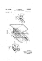
- . . Figure 2 is a .perspective sectional view of two. im-
- Figure 4 is a perspective view'of a single cyclone To illustrate my invention, I have shown how it can be employed in combination with a tobacco separating apparatus such as that shown in my prior Patent 2,755,930, granted July 24, 1956.
- the tobacco and dust separating apparatus consists'of a tobacco separator housing H, a detachable dust separator unit D, and a suitable source of suction E.
- the unstemmed tobacco leaves T are decointo the path of suitable combs 1Q secured toarevoly-..
- the torn tobacco and stem portion drop through the spaces between the serrated bars 22 onto a continuously moving belt 24 which hurls the torn tobacco and stem pieces toward an adjustable wall 26 into the air stream entering the separating apparatus at location A.
- the air stream is created-by the suction system B and torn tobacco is carried through the separating housing H by the air stream in the direction of the arrows shown in Fig. 1.- a 20
- the stem portions which have beenstripped clean of leaf lamina are more compact than the lamina and therefore offerless resistance to the lifting action of the incoming air stream.
- the stems drop through said openingof the housing into a suitable box or receptacle B.
- the guide plate 28 serves the important purpose of retaining the velocity of the air stream and preventing thestems with adhering tobacco from being pushed by the air stream back into the space between the'serrated bars 22 and belt 24.
- This door is provided-tor the purpose of controlling the amount of air in the vertical shaft of the separator housing H. I have found that while it serves the purpose for which it was intended the incoming air stream traveling in substantially the same direction as'the original one, often reinforced the latter stream to such an extent that it lifted up everything in its upward straight path including undesirable light Weight stems.
- another three sectional door 40 is provided.
- the latter is of substantially the same design as the doors 3 6, but doors 40 open inwardly and cause the incoming air stream to move downwardly and somewhat intercepting the up coming air stream and at the same time offsetting the air stream entering through doors 36. It is very noticeable that this combination or action of the intercepting air streams results in a very desirable turbulence with the effect of'spreading the tobacco in the separator housing over a much greater area and causing torn tobacco leaves to bounce in a criss-cross, back and forth, and up and down manner thereby resulting in a greater quantity of cleaner finished tobacco as well as a marked increase in separating efficiency.
- the rear chamber of the separator housing H is also provided with an inclined perforated plate 46 which permits any sand or heavy dust particles to drop through the perforations of said plate into a suitable chute 48 which leads to a suitable screw conveyor 50.
- the accumulated material is forwarded to a suitable gate valve 52 which discharges the material into a collector or receptacle 54.
- the rear portion of said rear chamber is also provided with a suitable screen 56 through which the dust laden air is exhausted and which separates lint, string and feathers from the air stream in this area.
- the dust laden air 58 passing out of the settling chamber S and drawn toward a cleansed air suction shaft 62, passes through the screen 56.
- the dusty air then passes into the lower pressure Zone on the downstream side of the screen 56 and into the bank 68 of contiguously joined outwardly flared intake ducts 70.
- These ducts are contiguously joined and sealed at their common points of extreme flare in such a fashion as to form a bank 68 of contiguous ducts 70 receiving their support only from each other and not from any other supporting member thereby avoiding the necessity for any wall area.
- This dust separator'duct bank 68 is securely fastened and its edges sealed within the housing D and cfiectively confines the incoming dust laden air 58, oflering it no alternative but to enter into the several dust separator ducts 7 0.
- the screen 56 prevents any leaves, lint or feathers from entering the intake ducts 70, and diffuses the air uniformly among all the ducts 70.
- each duct entrance being rectangular, when contiguously joined to each other to form a bank of ducts, the perimeter of said bank is therefor rec- .70-is connected to and blends in with the top end of a cylindrical-housing 78 of a cyclone dust separator 74 in a tangential and spiral fashion, as illustrated in Figures 2 and 4.
- All the cyclone dust separator units 74 are surrounded and supported at their girth at or near their midpoints by flanged openings 82, flanges 83 reinforcing the openings,
- the cyclone housing 78 on its lower end, is provided with a conical portion 80. Into the top portion of the cyclone housing 78 protrudes a tube 88 held in a suitable manner in the center of and coaxial with the housing 78, whereby an annular chamber 79 is formed between housing 78 and tube 88-.
- each separator 78 As the dustladen air 58 enters intothe tangential inlet duct of each separator 78, it is caused to spin around within the housing 78 in the annular space formed by its outer wall and tube 88.
- Clean air is drawn out through clean air tube 88 in the direction of arrows 90 through the center of the housing 78. Since the dusty air has the tendency to reach .the bottom of the intake tube 88 in the shortest possible sequent-rebounding from its opposing outer duct wall 104. Instead, the convex shape guides the dust air into tangential contact with the interior of the cyclone housing 78, thereby supporting an undisturbed tangential flow of the dust air resulting in greater cyclonic efl'iciency.
- the duct bottorn106 and the duct ceiling 108 may assume any form yielding the desired acceleration. This spinning action creates a centrifugal force separating the dust from the air, the dust being heavier, is thrown out of the open end of the conical portion 80 of said cyclone housing78.
- the clean air is exhausted from said cyclone housing 78 through the tube 88 into the clean air suction shafit62. Clean air exhaust shaft 86 is suitably connected to suction shaft 62 by one or more suction fans E, as can be seen in Fig. l, which through a suitable exhaust port 110, discharge the clean air 90 into the atmosphere from which it originated.
- a suitable screw conveyor 96 is mounted at the lower portion of the dust collecting chamber 94 to continuously remove the dust into a gate valve 112 from which the dust falls into a suitable receptacle 114.
- a separating apparatus for a tobacco processing machine comprising means for centn'fugally se'parating foreign particlesfrom 'a contaminated airstream, annular chambers formed in said separatingmeans, ducts having intake openings for guiding the contaminated air stream into the annular chambers ofsaid separating means, the inner surface of each'of said ducts defining a smoothwalled uninterrupted channel having an open cross-section from the intake opening thereof throughout the-annular chamber, the-intake opening of'said ducts being at an angle to said annular chamber, the surface area of the intake opening of said ducts having an outwardly flared form, all ducts being contiguously joined with each other at their extreme points of flare along all adjacent sections forming a bank and receiving their support'from each other, said duct bank being vertically positioned across the total area of active entrance of the contaminated air stream, and support means for said separatingmeans, said support means supporting said separating 'means in a'
- a separating apparatus for a tobacco processing machine comprising means for centrifugally separating foreign particles from a contaminated air stream, annular chambers-formed inv said separatingmeanavand ducts having intake openings for guiding the contaminated air stream into the annular chambers of said separating means, the inner surface of each of said ducts defining a smooth-walled uninterrupted channel having an open cross-section from the intake opening thereof throughout the annular chamber, each of said ducts being formed at its intake opening with a narrow rim of substantially straight sections, the intake opening of said ducts being at an angle to said annular chamber, the surface area of the intake opening of said ducts having an outwardly flared form, all ducts being contiguous'ly joined with each other at their points of maximum flare along all adjacent rim sections forming a bank and receivingtheir support from each other, said duct bank being positioned transversely across the entire contaminated air stream, thereby avoiding the use of any wall area transverse to said air stream.
- a separating apparatus for a tobacco processing machine comprising in combination, a bank of cyclone separators having outwardly flared ducts contiguously joined to each other at the points of extreme flare along all adjacent rim sections, each duct having an intake-opening opposing the flow of a contaminated air stream and being connected at its downstream portion with its own cyclone dust separator, each of said ducts being formed at its intake opening with a narrow rim of substantially straight sections, the inner surface of each of said ducts defining a smooth-walled uninterrupted channel having an open cross-section from the intake opening thereof throughout its separator, the intake opening of said ducts being at an angle to said dust separator, the adjoining walls of each -duct being joined so that one wall has a greater incline bank of cyclone separators having outwardly flared ducts v.contiguously joined to each other at the points of extreme flare along all adjacent rim sections, the adjoining walls of contiguously joined ducts having angles of inclination which differ from
- jacent rim sections 'to form a bank, said ducts having intake openings, each of said ducts being formed at its intake opening with a narrow rim of substantially straight sections, the inner surface of each of saicLducts defining ,a smooth walled uninterrupted channel having an open cross-section from the intake opening thereof through out its separator, the intake opening of said ducts being ;at an angle to said outlets said bank being placed verti- Tc'ally across-the entire active entrance area of a contaminated air stream, the ducts being flaredtodecrea'se resistance and noise and having the'contiguous walls of adjoining ;ducts having different degrees of incline with respect to the air stream so as to cause more air to move past. onewall than the other so as to prevent material from building up at said joinder.
- a separating apparatus for a tobacco processing machine comprising in combination a transverse bank of cyclone separators having outwardly flared ducts contiguously joined to each other at the points of extreme flare along all adjacent rim sections, each of said ducts being formed at its intake opening with a narrow rim of substantially straight sections, the inner surface of each of saidducts defining a smooth-walled uninterrupted channel having an open cross-section from the intake opening thereof throughout its separator, the intake of said ducts being at an angle to the outlet the adjoining walls of adjacent ducts being constructed and arranged so that one wall will have a steeper incline than the adjoining wall to prevent particles from straddling and building up on said joined walls, said ducts being flared to avoid the angular attack of high speed abrasive dust particles on the flared surface of the duct.
- a separating apparatus for a tobacco processing machine comprising an air passageway, means for moving a stream of contaminated air through said passageway, a bank of cyclone separators positioned vertically in front of the air stream, said separators having outwardly flared intake ducts contiguously joined together at their extreme outward flared edges along all adjacent rim sections to form a wall to wall surface of intake ducts across the contaminated air stream, each of said ducts being formed at its intake opening with a narrow rim of substantially straight sections, the inner surface of each of said ducts defining a smooth-walled uninterrupted channel having an open cross-section from the intake opening thereof throughout its separator, the intake opening of said ducts being at an angle to said outlet, the surface of adjacent contiguously joined ducts having different angles of inclination with respect to the air stream to cause a proportionately larger amount of air to flow past one surface than the adjoining surface to prevent material from straddling and piling up on said adjacent surfaces, and a diffuser interposed across the
- a separating apparatus comprising a housing, an air passageway formed in said housing, a tobacco separator chamber interposed in said passageway for separating torn tobacco leaves from said air stream, a bank of cyclone separators, said cyclone separators having outwardly flared ducts contiguously joined to each other along all adjacent rim sections and vertically interposed 57 across the entire cross sectional area of said air'streani so; as to avoid having any transverse wall area interposed in said air stream between said intake ducts to avoid turbulating the air stream at this point, each of said ducts being formed "at its intake opening with a narrow rim of substantially straight sections, the inner surface of each of said ducts defining a smooth-walled uninterrupted channel having an open cross-section from the intake opening thereof throughout its separator, the intakes of said ducts being at an angle to said outlets, the adjoining contiguously joined ducts having walls with diflerent angles of inclination with respect to the air stream to prevent material from accumul
- a separating apparatus comprising tobacco separator housing, a passageway formed in said housing, a source of torn tobacco leaves, means for delivering said torn tobacco leaves to said air passageway, means for causing a stream of air to flow through said air passageway, a settling area formed in said passageway to first remove tobacco stems, a second settling area for removing torn tobacco leaf lamina, a bank of small diameter cyclone separators for separating dust from an air stream, said "separators having outlets and intake ducts that are contiguously joined'with each other along all adjacent rim sections to avoid having a wall surface between the ducts, ,each of said ducts being formed at its intake opening with a narrow rim of substantially straight sections, the
Landscapes
- Cyclones (AREA)
Description
July 12,1960 7 o. E. EISSMANN TOBACCO sEPARA'riNc APPARATUS 2 Sheets-Sheet 1 Filed Aug. 9, 1957'- INV ENTOR OSWALD ERICH EISSMANN BY T 9M ATTORNEY y 1960 o. E. EISSMANN 2,944,629
' ToBAcco SEPARATING APPARATUS Filed Aug. 9, 1957 2 Sheets-Sheet 2 FIG. 2
lNVENTOR OSWALD ERICH EISSMANN -A TTORNEY .to corresponding parts throughout the ..In the accompanying drawings 7 Figure 1 is a sectional'side elevation of .of the improved dust separating apparatus.v
:Figure 3 is .a vertical sectional side view of proved'cyclo'ne dust separators contiguously --joined at their respective intake tapered ducts.
separator.
United States Patent TOBACCO SEPARATING APPARATUS Oswald Erich Eissmann, Richmond, Va., assignor to American Machine & Foundry Company, a corporation of New Jersey Filed Aug. 9, 1957, Ser. No. 677,314
9 Claims. (Cl. 183-34) in tobacco sepfcaused zones of turbulence in front of these areas. These M turbulent zones were objectionable because they caused pressure drops at these points." They also caused exces sive wear of the ducts, and there was an unnecessary accumulation of rebounding dust at the entrance chamber. In addition, there was an objectionable intake, noise inhe'rent in this design. v
It is therefore an object of my invention. to provide a separator having a filter which will eliminatel'these .zones of turbulence.
. A further object is to arrange the intake ducts so that they form one side of the separatingchamber. Y
1 A funther object is to provide meansfor equallydistributing the dust-laden airstream uniformly over all the individual cyclone separator inlet ducts, to thereby eliminate air pockets and turbulence which previously resulted in dust accumulating and settling downwardly in front of the inlet ducts. V I
Another object of this invention is to eliminate the necessity of employing means formerly required for removing dust settling downwardly in front of the inlets to the cyclone vseparators.
, Other objects and features of this invention will appear as the description of the particular physical embodiment selected to illustrate the invention progresses, In the accompanying drawings,; which forma part of this specification, likeIcharacters of reference have been applied several l views which make up the. drawings. a
the improved tobacco and dust separating apparatus.
. .Figure 2 is a .perspective sectional view of two. im-
. :Figure 4 is a perspective view'of a single cyclone To illustrate my invention, I have shown how it can be employed in combination with a tobacco separating apparatus such as that shown in my prior Patent 2,755,930, granted July 24, 1956.
In the embodiment shown in Fig. 1, the tobacco and dust separating apparatus consists'of a tobacco separator housing H, a detachable dust separator unit D, and a suitable source of suction E.
an example In operation, the unstemmed tobacco leaves T are decointo the path of suitable combs 1Q secured toarevoly-..
"2,944,629 Patented July 12, 196i) ice . I v v Y 2 ing drum 18. Combs =16, coacting with stationary rakes 20, 2.1 and 23 and a plurality of spaced semicircular serrated bars 22 surrounding said drum, cause the lamina to be torn from the stem portion of the leaves in a manner shown and described in my prior United States Patent 2,701,570, granted February 8, 1955.
Tearing of the lamina from the stem takes place when the combs 16 first engage with'the tobacco leaves. Additional tearing takes place when the leaves are forwarded past stationary rakes 20, 21 and 23 and serrated bars 22.
The torn tobacco and stem portion drop through the spaces between the serrated bars 22 onto a continuously moving belt 24 which hurls the torn tobacco and stem pieces toward an adjustable wall 26 into the air stream entering the separating apparatus at location A. The air stream is created-by the suction system B and torn tobacco is carried through the separating housing H by the air stream in the direction of the arrows shown in Fig. 1.- a 20 The stem portions which have beenstripped clean of leaf lamina, of course, are more compact than the lamina and therefore offerless resistance to the lifting action of the incoming air stream. As a result, the stems drop through said openingof the housing into a suitable box or receptacle B. The pieces of lamina and the stem portions which still have some lamina adhering thereto after being thrown off the belt 24 are intercepted by the incoming air stream and carried upward between the adjustable wall '26 and an air stream guide plate 28in the direction of the arrows. A a
The guide plate 28'serves the important purpose of retaining the velocity of the air stream and preventing thestems with adhering tobacco from being pushed by the air stream back into the space between the'serrated bars 22 and belt 24.
It has been found that without guide plate 28 the ve- 'locity of the air stream, entering from asubstant-ially narrower, opening, decreases because of the larger space between the bars 22 and belt 24 to such an extent that the stems with adhering tobacco tumble downward again and fall out of the air stream back onto the belt andrthe tobacco carried thereon. Such movement created a turbulence and started to entangle the tumbling tobacco with the newlyarriving tobacco which resulted in a rolling action of the entire mass.
During this rolling action, the stem portions engaged withacertain amount of free lamina and created a lump or ball similar to a snowball rolling down. a-hillside. After thislump became too big and heavy for the air "stream to support and roll, it simply dropped out of the opening of the incoming air and even sometimes choked the machine. v I 1 Ihavefound that I have overcome this difficulty by adding guide plate 28 and the stems with adhering tobacoo are carried upward and are deflected back by the deflector wall 30 into the range of action ofthe shredding drum 18 to be reprocessed. -It will thus be seenthat only clean individual stems fallout of the opening A into the chute or receptacle B. r r g All lamina including that hurled by centrifugal force from the shredding drum.18 travels upward and around the-horizontal bend 30 of the separator housing H. In- .completely stemmed tobacco is deflected back to the thresher in the manner described and claimed in my prlOr United States Patent 2,701,570, granted'February .8," 1955. The vertical forward Wall 32 of vertical shaft 34 of said housing H is provided with an air inlet door 36 which opens up outwardly and permits a predeterm ned amount of air to enter into the separating chamber at this point. Door 36 is made of three sections and :isshown and described in my United States Patent 2643,- .g ss anted June 30, 1953. This door is provided-tor the purpose of controlling the amount of air in the vertical shaft of the separator housing H. I have found that while it serves the purpose for which it was intended the incoming air stream traveling in substantially the same direction as'the original one, often reinforced the latter stream to such an extent that it lifted up everything in its upward straight path including undesirable light Weight stems.
To eliminate this undesirable action and to avoid the occasional objectionable accumulation of tobacco on the top surface of the stationary air stream guide plate 38, another three sectional door 40 is provided. The latter is of substantially the same design as the doors 3 6, but doors 40 open inwardly and cause the incoming air stream to move downwardly and somewhat intercepting the up coming air stream and at the same time offsetting the air stream entering through doors 36. It is very noticeable that this combination or action of the intercepting air streams results in a very desirable turbulence with the effect of'spreading the tobacco in the separator housing over a much greater area and causing torn tobacco leaves to bounce in a criss-cross, back and forth, and up and down manner thereby resulting in a greater quantity of cleaner finished tobacco as well as a marked increase in separating efficiency.
design and construction as the one shown in my prior United States Patents 2,701,570, granted February 8, 1955, and United States 2,755,930, granted July 24, 1956, and which deposits the cleaned lamina onto a suitable con- -veyor C. The rear chamber of the separator housing H is also provided with an inclined perforated plate 46 which permits any sand or heavy dust particles to drop through the perforations of said plate into a suitable chute 48 which leads to a suitable screw conveyor 50. The accumulated material is forwarded to a suitable gate valve 52 which discharges the material into a collector or receptacle 54. The rear portion of said rear chamber is also provided with a suitable screen 56 through which the dust laden air is exhausted and which separates lint, string and feathers from the air stream in this area.
' When the dust and leaf laden air stream enters the settling chamber S, it is very desirable that turbulence be kept at a minimum. My invention enables this objective to be attained by positioning all of the intake ducts of my dust separator across the entire air flow area which was formerly either completely or partially enclosed by a wall surface which resulted in undesirable turbulence and noises at this area.
Additional mechanism was also required in the type of separation apparatus formerly employed for the collection and removal of dust, sliding down the surface of a duct support wall. The dust collection and removal formerly required, consisting of a screw conveyor, a gate valve and a dust receptacle, is no longer necessary with my present apparatus. Its elimination is due to the fact that dust cannot escape from the suction airstream, as heretofore, by rebounding from the duct supporting wall surface or by virtue of air pockets, since there is neither wall surface nor air pockets.
The dust laden air 58, passing out of the settling chamber S and drawn toward a cleansed air suction shaft 62, passes through the screen 56. The dusty air then passes into the lower pressure Zone on the downstream side of the screen 56 and into the bank 68 of contiguously joined outwardly flared intake ducts 70. These ducts are contiguously joined and sealed at their common points of extreme flare in such a fashion as to form a bank 68 of contiguous ducts 70 receiving their support only from each other and not from any other supporting member thereby avoiding the necessity for any wall area.
This dust separator'duct bank 68 is securely fastened and its edges sealed within the housing D and cfiectively confines the incoming dust laden air 58, oflering it no alternative but to enter into the several dust separator ducts 7 0.
The screen 56 prevents any leaves, lint or feathers from entering the intake ducts 70, and diffuses the air uniformly among all the ducts 70.
In order to eliminate the turbulence and objectionable noise that resulted from the use of wall areas transverse to the air stream, and to improve efliciency by using the force of the entire air flow, I have made the cross-section of each duct rectangular. Each duct entrance being rectangular, when contiguously joined to each other to form a bank of ducts, the perimeter of said bank is therefor rec- .70-is connected to and blends in with the top end of a cylindrical-housing 78 of a cyclone dust separator 74 in a tangential and spiral fashion, as illustrated in Figures 2 and 4. v
All the cyclone dust separator units 74 are surrounded and supported at their girth at or near their midpoints by flanged openings 82, flanges 83 reinforcing the openings,
in a wall 84 common to all ducts, said flanged wall 84 separating thedust collecting chamber 94 from the filtered .air suction shaft 62-. The cyclone housing 78, on its lower end, is provided with a conical portion 80. Into the top portion of the cyclone housing 78 protrudes a tube 88 held in a suitable manner in the center of and coaxial with the housing 78, whereby an annular chamber 79 is formed between housing 78 and tube 88-.
As the dustladen air 58 enters intothe tangential inlet duct of each separator 78, it is caused to spin around within the housing 78 in the annular space formed by its outer wall and tube 88.
Clean air is drawn out through clean air tube 88 in the direction of arrows 90 through the center of the housing 78. Since the dusty air has the tendency to reach .the bottom of the intake tube 88 in the shortest possible sequent-rebounding from its opposing outer duct wall 104. Instead, the convex shape guides the dust air into tangential contact with the interior of the cyclone housing 78, thereby supporting an undisturbed tangential flow of the dust air resulting in greater cyclonic efl'iciency.
The duct bottorn106 and the duct ceiling 108 may assume any form yielding the desired acceleration. This spinning action creates a centrifugal force separating the dust from the air, the dust being heavier, is thrown out of the open end of the conical portion 80 of said cyclone housing78. The clean air is exhausted from said cyclone housing 78 through the tube 88 into the clean air suction shafit62. Clean air exhaust shaft 86 is suitably connected to suction shaft 62 by one or more suction fans E, as can be seen in Fig. l, which through a suitable exhaust port 110, discharge the clean air 90 into the atmosphere from which it originated.
The dust 92 discharged from the open end of the conical portion 80 of, each cyclone separator 74, falls into the dust collecting chamber 94. A suitable screw conveyor 96 is mounted at the lower portion of the dust collecting chamber 94 to continuously remove the dust into a gate valve 112 from which the dust falls into a suitable receptacle 114.
' if-What is claimedisz' v 1 A separating apparatus for a tobacco processing machine comprising means for centn'fugally se'parating foreign particlesfrom 'a contaminated airstream, annular chambers formed in said separatingmeans, ducts having intake openings for guiding the contaminated air stream into the annular chambers ofsaid separating means, the inner surface of each'of said ducts defining a smoothwalled uninterrupted channel having an open cross-section from the intake opening thereof throughout the-annular chamber, the-intake opening of'said ducts being at an angle to said annular chamber, the surface area of the intake opening of said ducts having an outwardly flared form, all ducts being contiguously joined with each other at their extreme points of flare along all adjacent sections forming a bank and receiving their support'from each other, said duct bank being vertically positioned across the total area of active entrance of the contaminated air stream, and support means for said separatingmeans, said support means supporting said separating 'means in a'region substantially'removed from the intake openings ofsaid'ducts, v v
2. A separating apparatus for a tobacco processing machine comprising means for centrifugally separating foreign particles from a contaminated air stream, annular chambers-formed inv said separatingmeanavand ducts having intake openings for guiding the contaminated air stream into the annular chambers of said separating means, the inner surface of each of said ducts defining a smooth-walled uninterrupted channel having an open cross-section from the intake opening thereof throughout the annular chamber, each of said ducts being formed at its intake opening with a narrow rim of substantially straight sections, the intake opening of said ducts being at an angle to said annular chamber, the surface area of the intake opening of said ducts having an outwardly flared form, all ducts being contiguous'ly joined with each other at their points of maximum flare along all adjacent rim sections forming a bank and receivingtheir support from each other, said duct bank being positioned transversely across the entire contaminated air stream, thereby avoiding the use of any wall area transverse to said air stream.
3. A separating apparatus for a tobacco processing machine comprising in combination, a bank of cyclone separators having outwardly flared ducts contiguously joined to each other at the points of extreme flare along all adjacent rim sections, each duct having an intake-opening opposing the flow of a contaminated air stream and being connected at its downstream portion with its own cyclone dust separator, each of said ducts being formed at its intake opening with a narrow rim of substantially straight sections, the inner surface of each of said ducts defining a smooth-walled uninterrupted channel having an open cross-section from the intake opening thereof throughout its separator, the intake opening of said ducts being at an angle to said dust separator, the adjoining walls of each -duct being joined so that one wall has a greater incline bank of cyclone separators having outwardly flared ducts v.contiguously joined to each other at the points of extreme flare along all adjacent rim sections, the adjoining walls of contiguously joined ducts having angles of inclination which differ from each other so as to cause more air to flow past one wall than the wall of the contiguous duct to pre vent the accumulation of material at the point of joinder of the duct walls, said duct bank having intake openings positioned transversely across a contaminated airflow so as to trap and guide all the contaminated air in the air stream into said cyclone dust separators, each of said ducts being formed at its intake opening with a narrow rim or substantially straight sections, the inner surfaceof each of "saidducts definingva smooth-walled uninterrupted channel having .an open cross-section from the intake opening thereof throughout its separator, the
jacent rim sections 'to form a bank, said ducts having intake openings, each of said ducts being formed at its intake opening with a narrow rim of substantially straight sections, the inner surface of each of saicLducts defining ,a smooth walled uninterrupted channel having an open cross-section from the intake opening thereof through out its separator, the intake opening of said ducts being ;at an angle to said outlets said bank being placed verti- Tc'ally across-the entire active entrance area of a contaminated air stream, the ducts being flaredtodecrea'se resistance and noise and having the'contiguous walls of adjoining ;ducts having different degrees of incline with respect to the air stream so as to cause more air to move past. onewall than the other so as to prevent material from building up at said joinder.
6. A separating apparatus for a tobacco processing machine comprising in combination a transverse bank of cyclone separators having outwardly flared ducts contiguously joined to each other at the points of extreme flare along all adjacent rim sections, each of said ducts being formed at its intake opening with a narrow rim of substantially straight sections, the inner surface of each of saidducts defining a smooth-walled uninterrupted channel having an open cross-section from the intake opening thereof throughout its separator, the intake of said ducts being at an angle to the outlet the adjoining walls of adjacent ducts being constructed and arranged so that one wall will have a steeper incline than the adjoining wall to prevent particles from straddling and building up on said joined walls, said ducts being flared to avoid the angular attack of high speed abrasive dust particles on the flared surface of the duct.
7. A separating apparatus for a tobacco processing machine comprising an air passageway, means for moving a stream of contaminated air through said passageway, a bank of cyclone separators positioned vertically in front of the air stream, said separators having outwardly flared intake ducts contiguously joined together at their extreme outward flared edges along all adjacent rim sections to form a wall to wall surface of intake ducts across the contaminated air stream, each of said ducts being formed at its intake opening with a narrow rim of substantially straight sections, the inner surface of each of said ducts defining a smooth-walled uninterrupted channel having an open cross-section from the intake opening thereof throughout its separator, the intake opening of said ducts being at an angle to said outlet, the surface of adjacent contiguously joined ducts having different angles of inclination with respect to the air stream to cause a proportionately larger amount of air to flow past one surface than the adjoining surface to prevent material from straddling and piling up on said adjacent surfaces, and a diffuser interposed across the contaminated air stream at -a point upstream from said intake ducts to cause a uniform amount of air to enter each of said intake ducts.-
8. A separating apparatus comprising a housing, an air passageway formed in said housing, a tobacco separator chamber interposed in said passageway for separating torn tobacco leaves from said air stream, a bank of cyclone separators, said cyclone separators having outwardly flared ducts contiguously joined to each other along all adjacent rim sections and vertically interposed 57 across the entire cross sectional area of said air'streani so; as to avoid having any transverse wall area interposed in said air stream between said intake ducts to avoid turbulating the air stream at this point, each of said ducts being formed "at its intake opening with a narrow rim of substantially straight sections, the inner surface of each of said ducts defining a smooth-walled uninterrupted channel having an open cross-section from the intake opening thereof throughout its separator, the intakes of said ducts being at an angle to said outlets, the adjoining contiguously joined ducts having walls with diflerent angles of inclination with respect to the air stream to prevent material from accumulating thereon.
9. A separating apparatus comprising tobacco separator housing, a passageway formed in said housing, a source of torn tobacco leaves, means for delivering said torn tobacco leaves to said air passageway, means for causing a stream of air to flow through said air passageway, a settling area formed in said passageway to first remove tobacco stems, a second settling area for removing torn tobacco leaf lamina, a bank of small diameter cyclone separators for separating dust from an air stream, said "separators having outlets and intake ducts that are contiguously joined'with each other along all adjacent rim sections to avoid having a wall surface between the ducts, ,each of said ducts being formed at its intake opening with a narrow rim of substantially straight sections, the
adjoining surfaces of contiguously joined ducts having different. angles of inclination. to, prevent material from accumulating on said surfaces, the cross sectional area ofsaid contiguouslyi joined intake ducts being coextensive with. the cross sectional; area of said air passageway in which it' is-inteiiposed to avoid. having any transverse wall, area, interposed-in the path of said air stream, the inner surface of each of said ducts defining asmoothwalled uninterrupted channel having an open cross-section from the intake: opening thereof throughout its separator, the intakes of said ducts being at an angle to said out.-
lets. e References Cited in the file of this patent UNITED STATES PATENTS I OTHER REFERENCES Petroleum Refiner, v01. 22, No. 8, August 1943, page 136.- I
Priority Applications (1)
| Application Number | Priority Date | Filing Date | Title |
|---|---|---|---|
| US677314A US2944629A (en) | 1957-08-09 | 1957-08-09 | Tobacco separating apparatus |
Applications Claiming Priority (1)
| Application Number | Priority Date | Filing Date | Title |
|---|---|---|---|
| US677314A US2944629A (en) | 1957-08-09 | 1957-08-09 | Tobacco separating apparatus |
Publications (1)
| Publication Number | Publication Date |
|---|---|
| US2944629A true US2944629A (en) | 1960-07-12 |
Family
ID=24718196
Family Applications (1)
| Application Number | Title | Priority Date | Filing Date |
|---|---|---|---|
| US677314A Expired - Lifetime US2944629A (en) | 1957-08-09 | 1957-08-09 | Tobacco separating apparatus |
Country Status (1)
| Country | Link |
|---|---|
| US (1) | US2944629A (en) |
Cited By (8)
| Publication number | Priority date | Publication date | Assignee | Title |
|---|---|---|---|---|
| US3545181A (en) * | 1968-05-07 | 1970-12-08 | Bernard W Young | Air cleaning apparatus |
| US3661159A (en) * | 1965-11-03 | 1972-05-09 | Seita | Apparatus for stemming tobacco leaves and separating the products obtained |
| US4913085A (en) * | 1985-01-01 | 1990-04-03 | Esb Elektorstatische Spruh-Und Beschichtungsanlagen G.F. Vohringer Gmbh | Coating booth for applying a coating powder to the surface of workpieces |
| US4915824A (en) * | 1985-08-12 | 1990-04-10 | Surtees Guy F | Pneumatic classifier for tobacco and method |
| US5205415A (en) * | 1991-07-10 | 1993-04-27 | The Standard Commercial Tobacco Co., Inc. | Modular classifier |
| US5325875A (en) * | 1987-08-24 | 1994-07-05 | Universal Leaf Tobacco Co., Inc. | Apparatus for separating threshed leaf tobacco |
| US5697293A (en) * | 1995-06-30 | 1997-12-16 | Delta Neu (S.A.) | Waste suction and storage device |
| US6435191B1 (en) | 1999-02-26 | 2002-08-20 | Dimon Inc. | Tobacco separator |
Citations (7)
| Publication number | Priority date | Publication date | Assignee | Title |
|---|---|---|---|---|
| US1717369A (en) * | 1923-05-11 | 1929-06-18 | Gen Motors Res Corp | Air cleaner |
| US1909184A (en) * | 1930-12-08 | 1933-05-16 | Int Precipitation Co | Centrifugal separator |
| US2515894A (en) * | 1947-09-16 | 1950-07-18 | American Blower Corp | Dust collector |
| FR1019343A (en) * | 1950-05-31 | 1953-01-20 | Rechauffeurs D Air Aireco Soc | Improvements to the construction of centrifugal dust collection devices |
| US2643737A (en) * | 1950-07-06 | 1953-06-30 | Dustex Corp | Apparatus for separating particles from gases |
| FR1097828A (en) * | 1953-04-11 | 1955-07-11 | Hjorth & Co Ab | Dust separator |
| US2755930A (en) * | 1951-04-06 | 1956-07-24 | American Mach & Foundry | Tobacco and dust separating apparatus |
-
1957
- 1957-08-09 US US677314A patent/US2944629A/en not_active Expired - Lifetime
Patent Citations (7)
| Publication number | Priority date | Publication date | Assignee | Title |
|---|---|---|---|---|
| US1717369A (en) * | 1923-05-11 | 1929-06-18 | Gen Motors Res Corp | Air cleaner |
| US1909184A (en) * | 1930-12-08 | 1933-05-16 | Int Precipitation Co | Centrifugal separator |
| US2515894A (en) * | 1947-09-16 | 1950-07-18 | American Blower Corp | Dust collector |
| FR1019343A (en) * | 1950-05-31 | 1953-01-20 | Rechauffeurs D Air Aireco Soc | Improvements to the construction of centrifugal dust collection devices |
| US2643737A (en) * | 1950-07-06 | 1953-06-30 | Dustex Corp | Apparatus for separating particles from gases |
| US2755930A (en) * | 1951-04-06 | 1956-07-24 | American Mach & Foundry | Tobacco and dust separating apparatus |
| FR1097828A (en) * | 1953-04-11 | 1955-07-11 | Hjorth & Co Ab | Dust separator |
Cited By (10)
| Publication number | Priority date | Publication date | Assignee | Title |
|---|---|---|---|---|
| US3661159A (en) * | 1965-11-03 | 1972-05-09 | Seita | Apparatus for stemming tobacco leaves and separating the products obtained |
| US3545181A (en) * | 1968-05-07 | 1970-12-08 | Bernard W Young | Air cleaning apparatus |
| US4913085A (en) * | 1985-01-01 | 1990-04-03 | Esb Elektorstatische Spruh-Und Beschichtungsanlagen G.F. Vohringer Gmbh | Coating booth for applying a coating powder to the surface of workpieces |
| US4915824A (en) * | 1985-08-12 | 1990-04-10 | Surtees Guy F | Pneumatic classifier for tobacco and method |
| US5325875A (en) * | 1987-08-24 | 1994-07-05 | Universal Leaf Tobacco Co., Inc. | Apparatus for separating threshed leaf tobacco |
| US5476109A (en) * | 1987-08-24 | 1995-12-19 | Universal Leaf Tobacco Co., Inc. | Apparatus for separating threshed leaf tobacco |
| US5205415A (en) * | 1991-07-10 | 1993-04-27 | The Standard Commercial Tobacco Co., Inc. | Modular classifier |
| US5358122A (en) * | 1991-07-10 | 1994-10-25 | The Standard Commercial Tobacco Company, Inc. | Multiple stage tobacco classifier |
| US5697293A (en) * | 1995-06-30 | 1997-12-16 | Delta Neu (S.A.) | Waste suction and storage device |
| US6435191B1 (en) | 1999-02-26 | 2002-08-20 | Dimon Inc. | Tobacco separator |
Similar Documents
| Publication | Publication Date | Title |
|---|---|---|
| US4198290A (en) | Dust separating equipment | |
| US4721561A (en) | Centrifugal force separator | |
| US6238451B1 (en) | Vacuum cleaner | |
| RU2624875C2 (en) | Cyclone separator device | |
| US3661159A (en) | Apparatus for stemming tobacco leaves and separating the products obtained | |
| US20090158932A1 (en) | Particle separator | |
| US9901232B2 (en) | Vacuum cleaner | |
| US3360125A (en) | Tobacco-leaf separator | |
| US3864106A (en) | Concentrator system for particulates suspended in air | |
| US2988213A (en) | Tobacco separating apparatus | |
| US2944629A (en) | Tobacco separating apparatus | |
| US2290664A (en) | Separating apparatus | |
| US2633930A (en) | Centrifugal air separator for removal and classification of particles | |
| US2047568A (en) | Method and apparatus for separating suspended particles from gases | |
| JP4640542B2 (en) | Cyclone | |
| US2755930A (en) | Tobacco and dust separating apparatus | |
| US3042202A (en) | Cyclone classifier | |
| US4646759A (en) | Vibrating trough tobacco separator and classifier | |
| US2001184A (en) | Classifier | |
| US2701570A (en) | Apparatus for threshing and winnowing tobacco leaves | |
| US1861247A (en) | Air classifier | |
| CN105286079A (en) | Method for separating and collecting tobacco fines generated after tobacco stems are threshed and redried | |
| US2643768A (en) | Separating apparatus | |
| RU2220642C2 (en) | Cyclone with dust catcher | |
| US3960526A (en) | Particle separating apparatus |