US2942259A - Broad band television antenna - Google Patents
Broad band television antenna Download PDFInfo
- Publication number
- US2942259A US2942259A US613710A US61371056A US2942259A US 2942259 A US2942259 A US 2942259A US 613710 A US613710 A US 613710A US 61371056 A US61371056 A US 61371056A US 2942259 A US2942259 A US 2942259A
- Authority
- US
- United States
- Prior art keywords
- band
- antenna
- low
- dipole
- rods
- Prior art date
- Legal status (The legal status is an assumption and is not a legal conclusion. Google has not performed a legal analysis and makes no representation as to the accuracy of the status listed.)
- Expired - Lifetime
Links
Images


Classifications
-
- H—ELECTRICITY
- H01—ELECTRIC ELEMENTS
- H01Q—ANTENNAS, i.e. RADIO AERIALS
- H01Q9/00—Electrically-short antennas having dimensions not more than twice the operating wavelength and consisting of conductive active radiating elements
- H01Q9/04—Resonant antennas
- H01Q9/16—Resonant antennas with feed intermediate between the extremities of the antenna, e.g. centre-fed dipole
-
- H—ELECTRICITY
- H01—ELECTRIC ELEMENTS
- H01Q—ANTENNAS, i.e. RADIO AERIALS
- H01Q5/00—Arrangements for simultaneous operation of antennas on two or more different wavebands, e.g. dual-band or multi-band arrangements
- H01Q5/40—Imbricated or interleaved structures; Combined or electromagnetically coupled arrangements, e.g. comprising two or more non-connected fed radiating elements
- H01Q5/48—Combinations of two or more dipole type antennas
Definitions
- the present invention relates to television antennas adapted to receive both high-band and low-band television signals and-more particularly to such antennas incorporating means for tuning the antenna to particular television channels.
- the Rabbit Ears antenna is basically a straight single dipole, which has an impedance of about 72 ohms at resonance, and therefore the Rabbit Ears antenna is inherently mismatched to the conventional BOO-ohm transmission line. In practice, the Rabbit Ears antenna is even more seriously mismatched because its inipedance is often even less than 72 ohms unless it is ca efully adjusted to one-half wavelength for the particular there is a still further loss in antenna efiiciency.
- Rabbit Ears antennas are generally constructed so that the Ears telescope and hence .their length can be changed, ostensibly to tune, the antenna to the channel being received. In practice, however, the act of tuning the antenna "by adjusting the arm length loads the antenna'and temporarily changes its characteristics so that it is virtually impossible for the average viewer to determine the :correct length for optimum reception.
- the present invention provides a 'distinct departure from the Rabbit Ears antenna and modifications of the Rabbit Ea-rs antenna which are common inthe indoor antenna art.
- the present antenna isof fixed length and shape, and includes special means to function efliciently for both the low-band VHF television channels (extending in frequency from 64 to 88 megacycles) and Patented Juarez-1, 1960 the high-band VHF television channels (extending in frequency from 174 to 216 megacyc'les).
- antenna incorporates a tuning mechanism to provide optimum reception at any desired VHF television channel, the same tunning mechanism being useful both on low-band and on high-band operation, although operating on different principles for the two bands.
- the tunability feature also serves to reject interference at other frequencies.
- the tuning mechanism of the present invention does not require changes in the antenna length or size or shape but is accomplished merely by turning a tuning knob to the desired channel number.
- an antenna according to the present invention may be made very small compared ,to the ordinary Rabbit Ears" antenna.
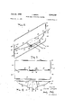
- FIG. 1 is a top plan view of an indoor television antenna according to the present invention partially cut away to show the internal construction of the cap at the right extremity of the antenna as viewed in the figure;
- Fig. 2 is a front elevational view of the antenna shown in Fig. 1;
- Fig. 3 is a side elevational view of the antenna shown in Fig. 1; I
- Fig. 4 is a fragmentary perspective view of one end of the antenna showing an alternative construction for the end-hat structure of the antenna;
- Fig. 5 is a vertical sectional view of the antenna show ing the alternative end-hat of Fig. 4;
- Fig. 6 is a fragmentary top plan view of the antennae showing the alternative end hat of Fig. 4.
- Fig. 7 is a fragmentary horizontal sectional View of the central housing of the antenna shown inFig. ,1;
- Fig. 8 is a vertical sectional view of the central antenna housing taken along the line 8-8 in Fig. 7; a
- Fig. 9 is a fragmentary vertical sectional view of the central housing taken along the line 9-9 in Fig. 7;
- Fig. 10 is a fragmentary vertical sectional view of the tuning assembly taken along the line lid-10 in Fig. 7
- Fig. 11 is a fragmentary vertical sectional-view .of the tuning coil taken along the line 11--,11 in Fig. 10;
- Fig. 1.2 is a'fragmentary vertical sectional view .of the tuning'drivehelix taken along the line 12-12 in Fig. 10;
- Fig. 13a is a schematic circuit diagram of the-electrical circuit of the antenna shown in Fig. 1;
- an antenna base 10 is provided to support the I antenna.
- the antenna base 10 has three legs 11 forming a tripod support for the antenna. If desired, the legs 11 may be provided with protective caps 12 which may be of rubber, plastic or some similar material and serve to protect the surface of a piece of furniture or the like upon which the antenna may be placed.
- a tuner housing 14 is pivotally mounted on the antenna base 10.
- the tuner housing 14 is provided with a front panel 15 on which is mounted a rotatable tuning knob 16.
- the tuning knob 16 is aflixed to a shaft 17 extending into the interior of the tuner housing 14.
- On the front of the tuner knob 16 there is provided an outer dial 19 and an inner dial 18.
- the channel numbers of the television channels in the high band are placed on the outer dial 19 while the channelnumbers of the television channels in the low band are placed on the inner dial 18, at appropriate points determined in the manner indicated below.
- An indicator arrow or index 22 is provided at the top of the housing 14 which cooperates with the numbers on the dials 18 and 19 to indicate the television channels to which the tuner is set.
- a suitable transmission line 23 extends out the bottom of the tuner housing 14 and throughthe open center of the antenna base 10 for connection to the televisoin receiver.
- a low-band antenna rod 24 extends outwardly from each side of the tuner housing 14.
- Two high-band antenna rods 25 extend outwardly from the housing 14 on either side of and parallel to each of the low band rods 24 and in the same horizontal plane therewith.
- the rods 24 and 25 are constructed of a conductive material and in the preferred construction shown in the drawings, the center or low-band rod 24 has a slightly greater diameter (for example, 3A diam.) than the high-bandrods 25 (for example, A" diam.). In another form, the rods may be of equal diameter, say W
- the diameters of the rods 24 and 25 are not particularly critical but should be large enough to provide a rigid structure for the antenna.
- the length from tip to tip in the preferred construction shown in the drawings is approximately 19" for the high-band rods 25 and approximately 21" for the low-band antenna rods 24.
- the antenna shown provides a very compact structure.
- the physical lengths of television .dipole antenna rods are invariably somewhat critical unless compensated electrically, and such is the case with an antenna according to the present invention.
- the antenna shown includes a tuning inductance which will subsequently be described, and hence an adjustment of the value of the inductance in the tuning assembly is made to compensate for substantial variations in the effective electrical lengths of the antenna rods from channel to channel. It is believed, however, that the constuction and dimensions described are preferable from the standpoint of compactness and efficiency.
- caps 26 Attached to the ends of the antenna rods 24 and 25 are respective caps 26.
- the caps are of non-conductive material and each is provided at their inmost edges with holes 27 for the entrance of the high-band rods 25 and a hole 28 for the entrance of the respective low-band rod 24.
- the caps 26 are constructed of an upper cap section 26a and a lower cap section 26b which are fastened together by means of bolts 30 or by other suitable fasteners.
- the lower cap sections 26b as shown in Fig. 1
- End hats 31 are provided at the ends of the antenna rods 24 and 25 and are secured thereto by means of the cap 26.
- the end hat 31 is constructed of a rectangular vertical closed loop 33 of conductive material and a horizontal triangular brace member 32 interrupted at its inner vertex and with its other vertices secured respectively to the centers of the short sides of the loop member 32.
- the end hats 31 may be constructed of any conductive material and are preferably constructed of a material similar to that used for the rods 24 In the particular antenna shown the end hats are from five to six inches by 10 to 12 inches. However, the dimension of the end hats is less critical than the antenna roddimensions.
- the function of the end hats 31 is to provide a conductive structure of substantial area at the ends of and connected to the rods 24 to provide an end loading capacitive impedance for the lowband antenna.
- the effect of such a structure is to pro vide an increase in the effective length of an antenna rod 24 to which it is electrically connected.
- the end hat 31 is physically secured to the cap 26 by means of holes 34 through which the brace members 32 pass and by means of a notch 35a in the upper cap member 26a and a slot 35b in lower cap member 261) so that the ends of the brace member 32 may be secured between the cap members 26a and 26b.
- the slot 35b allows the ends 32a of brace 32 to be disengaged from cap 26 so that end hat 31 may be folded by pivoting it about the holes 34 in the cap 26.
- the end hat 31 may thus be folded from its operative vertical position to a horizontal position whereby the antenna is more nearly flat and occupies a lesser volume and may be more readily stored and transported.
- Figs. 4, 5 and 6 show an alternative construction for the end hat 31.
- the end hat 31 is constructed of two identical frame sections which are so shaped that each forms a half of the end hat.
- Each frame section 80 has a loop portion 81 having a long side 82 and two short sides 83 and 84.
- a brace portion 85 is adapted to retain the loop in position with respect to a cap member 26.
- the brace portion 85 has a short section 86 in the plane of the loop and joining it to section 83.
- the brace portion 85 is bent at an angle to the plane of the loop, and is in a plane perpendicular to the short sides 83 and 84.
- the end of the brace 85 is adapted to fit in a slot 35b in the end cap 26 in a manner similar to that shown in Figs. 1-3.
- Half of the central cross piece of end hat 31 is formed by the center section 87.
- This center section 87 is bent at a right angle to the side 84 and lies in the plane of the loop.
- An offset portion 88 is provided at the outer end of the center section 87 which is of a length somewhat longer than the joining section 86.
- two of the frame sections 81 may be welded or otherwise fastened together at 89 where the offset and joining sections adjoin to form an end hat 31' as shown in Figs. 4-6.
- the shape of the frames 80 is such that an end hat 31' is formed which is substantially the same shape as the end hat 31 shown in Figs. l-3.
- the end hats have a maximum dimension approximately equal toogsli'ghtly' less. than the length of one of the rods 24 or
- the end hats 31 or 31' are not electrically connected to the high-band rods 25 due to the insulating properties of the webs 29' of cap 25.
- the end hats 31 or 31 are, however; electrically connected to the center low-band rod 24 bymeans of a contact or clip 36.
- end hat 31 serves as an end loadingstructure for the low-band antenna system. Although particular types of endhat structures are shown, it should be understood that any equivalent end-loading structure couldibe provided to serve to increase the efiective or electrical length of low-band antenna rods. 24 and", lower the frequency at which the low-band antenna system hasthe. desired. frequency-impedance. characteri'st-ics.
- the inner connections of the antenna rods 24 and 25 in. housing. 14. are. shown in Fig. 7..
- Anoifset 37 is. provided at the base of the U for attaching: the high-band rods in the central housing 14. by means. of rivets 38. passing through holesin columns. 39 formedas anintegral part of the lower portion 1421 of central housing 14;
- Webs 41- having slots- 42 are provided to secure the low-band rods 24 in the central housing 14.
- a bridge member 43 passesrover each low-band rod 24 and is secured. in the slots 42. In some forms of construction this,.bridge member 43 may be omitted.
- the high-band rods 25.pass1 over thejends of bridges 43 and hence retain. bridges tTa; andthe rods 24 in place.
- the ends 40 of the low-band rods 24 are bent, upward and outward as seen most clearly in Fig. 8 to provide. a separation between'thevlowband rod and the high-band rod ends and. avoidundesirable electrical coupling.
- The. tuner mechanism is contained in a tuner housing 44.
- the rear endof the tuner housing 44 is provided with L-shaped projections- 45 which. are engaged by; the. tunerhousing bracket 47" forsupporting the rear end of the tuner housing 44.
- Projections 46 on the front endof: the-tuner housing 44 rest on a front bracket es thereby supporting; the frontendof the tuner housing 44.
- Acylinder- 49-iir the front. part of" the tuner housing 44 is provided to'retainthe tuningcam 51 (seen in Fig. 10).
- Thetuningcam 51 is connected to the tuner knob shaft 1-7-whichis in turn'connected to the tuner knob 16. R- tation' of; the tuning knob 16- therefore causes a corresponding rotation: of the tuning cam 51.
- A- helicali web- 52 encircles. and is preferably molded integrally with the tuning cam 51.
- a core-sliding bar 54 extends lengthwise in the tuner housing 44 and is slidably retained in thebar slot 53 formed in the rearward portion of tuner housing 44.
- a pair of projections 55 extending downward from the front end of the tuning bar 53 engage either side of the helical web 53 on the tuning cam 51, being spaced from one another in an axial direction;
- ThllSwflSlhE tuning knob 16 and the tuning cam 51 are rotated, the helical web 52 causes a translatory movement of the tuning bar 54.
- the tuning bar 54 is provided with aforward projection 56 and a rear projection. 7;. Between these forward and rear projections, four tuningrcores 58a, 59a, 58b, and 5% are slidably retained: in a. cylindrical core. chamber 61 Within tuner housing 44R Bhcircling. the core chamber 61 are two wire: coils 62;.
- the inductances of the coils 62 are increased, and as the cores 59 are moved into the coils 62 replacing the cores 58, the coil inductanc'es arede creased;
- the housing 14 has an annular shoulder 65' which rests on an annular plate 66 which forms the top of the tripod base 10.
- a cylindrical projection 64 on the bottom of the housing 14 fits within the opening in the annular plate 66.
- Latch sections 67 are provided in the cylindrical projection 64 which are resilient and have recesses 68 for permitting grasping the latch sections 67 to press them inward for release. Facing outward-on each latch section 67 is a projection 69 which engages a recess 71 in the base 10 and thus holds the base 19 and housing 14 together.
- the housing '16 is thus free to rotate on the base 10 and may be removed from the base 16 for packaging or storing by inserting the thumb and forefinger in the recesses 68 and pressing the latch sections 67 inward to release them from the base cylinder 64.
- the approximate equivalent electrical circuit of the antenna is shown in Fig. 13A.
- the two high-band rods extending to each side of the antenna are shown at 25.
- the low band rods are shown at 24, with the end hats 31 attached at their outer ends.
- Each pair of the highband rods 25 is electrically joined together at their inner ends,and the junction is connected by means of respective oneof the variable inductances 62 to the inner end of'the corresponding low-band rod 24.
- Each joined pair of inner ends of the high-band rods 25 is connected to a respectivetapon an autotransformer 50 also shown in Figs. 7 and9.
- the end terminals 63 of the autotransformer 50 are adapted to be connected to transmission line 23.
- the antenna is composed of two parts: a high-band section shown in Fig. 133 and a low-band section shown in Fig. 130.
- the high-band section consists essentially of a high-band dipole each arm of which is formed by a pair of parallel rods 25, and which is connected to an impedance-transforming autotransformer 63. It should be understood that an equivalent imped'ance-transforming device could be used in place of the autotransformer 50 shown in the preferred construction.
- the low-band section of the antenna as shown in Fig. 13C consists of a dipole having arms 24 with end hats 31 and variable center-loading series inductances 62.
- the low-band section of the antenna is connected to the same taps on the autotransformer St or, in other words, is connected in parallel with the high-band section shown inFig. 12B.
- the high-band and the low-band sections are connected inparallel, they obviously have an influence upon each other.
- the high-band section has relatively little influence upon the low-band section" when operating on low-band channels.
- the reverse is not correct; the operation of the high-band section at high band frequencies is definitely affected by the fact that the lowband antenna is effectively connected in parallel, and this effect is utilized here, as is shown below.
- the rods 24 are considerably shorter than required for a tuned simple dipole at any lowband channel.
- a dipole formed of arms 24 alone would have a substantial capacitive reactance but a low radiation resistance of the order of 3 ohms, a far cry from the desired matching line-impedance of 300 ohms.
- the hats 31 provide end-loading which increases the effective length of the antenna and increases its resistance to the order of 30 ohms, but leaves the impedance highly capacitive. The hats actually do not receive radiation because their front and rear halves have opposite and cancelling induced currents.
- the series inductances 62 serve to compensate for the effective capacitance of the arm plus hats.
- the inductances 62 are variable to provide means for-tuning the antenna to the various low-band channels in the preferred construction shown. It should be understood that tunability is a highly desirable, but is not a necessary feature of certain aspects of the invention where approximate impedance-matching can be tolerated.
- the particular means for adjusting the inductances is of special utility here because it provides the desired wide variation in inductance (both above and below that of the coils with cores removed) with relatively small adjustment.
- the antenna for each low-band channel appears as a pure resistance of about 30 ohms.
- the high-band section merely adds a certain amount of capacitance, which joins as part of the total capacitance compensated by the coils 62.
- This 30-ohm value is raised to the required 30-ohm value by the autotransformer 50.
- the transformed impedance value be less than 300 ohms (say, about 200 ohms) to provide greater band width and more uniform frequency characteristics over each channel band.
- end-loading hats also solves the important problem of band-width.
- the dipole could not be closely enough resonated over a sufficient band-width to cover even a single channel, and a step-up ratio of 100 to l for the autotransformer would then prevent uniform stepped-up impedance over the channel width.
- the hats avoid these difficulties (especially crucial for color television) by increasing the natural radiation resistance and by reducing the required step-up ratio.
- the low band'section represents an impedance in parallel with the high-band dipole formed by rods 25.
- the low-band dipole arms 24 could be considerably shorter than those for the shortest half-wave high-band dipole, so that the high-band arms 25 are also shorter than for such a halfwave dipole, and offer a capacitive impedance over the entire high-band.
- This capacitive impedance can be tuned by adjusting the same tuning mechanism so that the low-band section presents an effective inductance resonating with the high-band section.
- the radiation resistance of the high-band section on. high-band channels is selected to have the proper value, and a flat frequency response is attained, by having each high-band arm in the form of parallel rods 25 forming a U, simulating a flat dipole having fiat frequency response.
- the tuner knob 16 therefore has two concentric dials, respectively'calibrated for low-band and high-band channels, so that in each case, positioning of knob 16 so that the received channel number is opposite the index mark, will set the variable inductances to the proper value regardless of which band is being received.
- the high-band antenna may be constructed of a length shorter than an ordinary tuned high-band half-wave dipole by reason of the fact that the low-band section and the associated inductances 62 are connected in parallel with the high band section, permitting smaller overall size of antenna.
- Fig. 14 where clip 36a has extensions approximately one inch long parallel to and spaced from rods 25 by dielectric spacing walls 36b, thus providing extra capacitance for rods 25 effective substantially only in the high-band,
- the overall length of the antenna may be of the order of 19 inches; with rods 25 approximately the same length as rods 24.
- the autotransformer 50 may have different characteristics at different frequencies or hands. This is immaterial in the present invention, since such variations can generally be compensated by proper adjustment of the variable inductances. In some lowimpedance antenna applications, the autotransformer may be omrnitted entirely.
- a compact dual-band antenna operable on high and low bands comprising a first dipole having arms shorter than required for resonance at every frequency in said high band, whereby said first dipole presents a capacitive impedance throughout said high band; a second dipole having arms parallel and closely spaced to not more than one-eighth wavelength of the maximum antenna frequency from said first dipole arms; capaci- 9 r tive 'endJpading means for said second dipole; (IDQIRX'iS? ing respectiye, conductive structures 'at; tl ie ends ofsai'cl first dipole arms, and means'operative to tune. said antenna to frequencies in both said h gh.
- said low bands comprising a pair of adjustable-inductance coils each connected betweemafirst dipole-aarm inner end and a corr spond ng: e ond d po ealm nner. end, wh re y when viewed at the said first dipeleiarm innenends-said.
- coils may tune said second dipole andend-loading means to frequencies in said low band and may incombination with said second dipole and end-loading means present a parallel inductance tuning said first dipole to frequencies in said high band.
- a multi-band antenna suitable for television reception on low and high frequency bands where said high band has frequencies substantially higher than said low band comprising a high-band dipole operative at frequencies in the high band, a low-band dipole in parallel relation to and spaced not more than one-eighth wavelength of the maximum antenna frequency from said high-band dipole, a conductive end-loading structure at each end of said high-band dipole, said structure being conductively connected to said low band dipole and not directly in electrical contact with the outer end of said high band dipole, means for electrically connecting said dipoles in parallel, and means for connecting a transmission line to said parallel connected dipoles, whereby said antenna has desirable impedance-frequency characteristics at both the low frequency band and the high frequency band.
- An antenna as claimed in claim 2 further including an inductive reactance element in series with each arm of said low-band dipole for causing said antenna to be resonant at frequencies in the low band as well as in the high band.
- An antenna as claimed in claim 2, wherein said means for connecting a transmission line comprises an impedance-transforming element for substantially matching the antenna impedance to the characteristic impedance of a transmission line.
- A'dual-band television antenna comprising a highband dipole having arms shorter than required for reso nance at frequencies in the high VHF television band, a low-banddipole having arms in close spaced parallel relation thereto, a conductive end-loading structure at each end of said high-band dipole, said structure being conductively connected to said low-band dipole and not directly in electrical contact with the outer end of said high-band dipole, a respective inductance electrically connected in series with each arm of said low-band dipole, said series combination of low-band dipole and inductances being electrically connected in parallel with said high-band dipole, impedance-matching means connected to said parallel-connected dipoles and including terminals for connecting a transmission line to said antenna, whereby an antenna is provided operable in both the low VHF television band and the high VHF television band.
- each said end-loading structure comprises a loop of conductive material having a conductive cross member, said cross member being connected to a respective low-band rod at a point substantially at the center of said loop.
- a dipole antenna comprising a pair of aligned rods, an insulating mounting at the end of each arm, a pair of rigid closed planar loops of conductive material, a conductive cross-member extending across each said loop, and means securing each said cross-member on a respective one of said mountings with its center in electrical connection with the corresponding rod, said loop planes being perpendicular to said rods said mounting supporting said loops with respect to said rods with portions of said loops out of direct electrical contact with said rods.
- each said loop, and cross-member are formed from two identical-shaped rods joined together.
- a multi-band antenna suitable for television reception on low and high frequency bands where said highband has frequencies substantially higher than said lowband, said antenna having a high-band dipole having two arms, a low-band dipole, a conductive end-loading structure at the end of each of said high-band dipole arms and conductively connected to said low-band dipole, the improvement comprising means for capacitively coupling each arm of said high-band dipole to a corresponding endloading structure, said capacitive coupling means comprising a spacer of solid dielectric material placed between a portion of each said high-band dipole arm and an adjacent part of the corresponding end-loading structure.
- a m-ulti-band antenna suitable for television reception on low and high frequency bands where said highband has frequencies substantially higher than said lowband comprising a high-band dipole having two arms, a low-band dipole having two arms, an adjustable reactance element coupling each inner end of said high-band dipole arm to a respective inner end of the corresponding lowband dipole arm, and output terminals coupled to the inner ends of said high-band dipole arms, whereby said low-band dipole may be tuned by adjustment of said reactances effectively in series therewith and said high-band dipole is tunable by the series combination of said adjustable reactances and low-band dipole arms which together are efiectively in parallel with said high-band dipole, said high-band dipole being in parallel relationship to said low-band dipole and spaced therefrom not more than one-eighth wavelength at the maximum antenna frequency.
- each said adjustable reactance is an adjustable inductance.
- An antenna as claimed in claim 17 including means 2,281,429 mechanically coupling said adjustable reactances for si- 2,558,145 multaneous adjustment. 2,611,086
Landscapes
- Physics & Mathematics (AREA)
- Electromagnetism (AREA)
- Details Of Aerials (AREA)
Description
June 21, 1960 J. GREEN 2,942,259
BROAD BAND TELEVISION ANTENNA Filed Oct. 3, 1956 5 Sheets-Sheet 1 IN VEN TOR.
JZ/L/US GREEN BY A TTOEA/C'VS June 21, 1960 J. GREEN 2,942,259
. BROAD BAND TELEVISION ANTENNA Filed Oct. 3, 1956 5 Sheets-Sheet 2 IN VEN TOR. JZ/L/us GREEN BY A TTOEA/EVJ' J. GREEN BROAD BAND TELEVISION ANTENNA June 21, 1960 5 Sheets-Sheet 3 Filed 001;. 3, 1956 j a 4 W r 2 a W 7 Z fi M 4 1 Z T WW 0 2 w 5 8 a W 4 lo 4 4 54 4 4 0/ 7O w v H i A a Q m 5 f 4 /o d 7 a 4 v 4 m/ 3 0 4/ a a fi uw 4 3 T z m 5 I? ll/W INVENTOR J UL/US GEL-"5N BY 8 g i A I ATmkA/Ey:
Jlme 21, 1960 J. GREEN 2,942,259
BROAD BAND TELEVISION ANTENNA Filed on. s, 1956 5 Sheets-Sheet 4 Tic. E
I il I o f 65 a /0 47 44 A? q 4a 47 INVENTOR.
J11 /us GREEN i Z Arron/Ev;
June 21 1960 J. GREEN 2,942,259
BROAD BAND TELEVISION ANTENNA Filed Oct. 3, 1956 5 Sheets-Sheet 5 Tia. 13A.
IN V EN TOR. J14 /us GRN g i; RNEYS United States Patent 2,942,259 BROAD BAND TELEVISION ANTENNA Julius Green, Ellenville, N.Y., assignor to Channel Master Corporation The present invention relates to television antennas adapted to receive both high-band and low-band television signals and-more particularly to such antennas incorporating means for tuning the antenna to particular television channels.
Substantial difliculty has been encountered in designing a television antenna suitable for indoor use which is moderately compact and yet satisfies the requirements for an'etlicien-t television antenna. The most widely accepted indoor television antenna at the present time is the Rabbit Ears antenna, utilizing a pair of telescoping arms of adjustable length, inclined to the horizontal at .adjustable angles. Virtually all indoor antennas in use today are Rabbit Ears antennas or modifications of the Rabbit Ears antennas. This antenna, however, has numerous inherent deficiencies which have not been satisfactorily overcome by modifications, such as adding spiral coils, adding loops, or incorporating switching arrangements for tuning.
The Rabbit Ears antenna is basically a straight single dipole, which has an impedance of about 72 ohms at resonance, and therefore the Rabbit Ears antenna is inherently mismatched to the conventional BOO-ohm transmission line. In practice, the Rabbit Ears antenna is even more seriously mismatched because its inipedance is often even less than 72 ohms unless it is ca efully adjusted to one-half wavelength for the particular there is a still further loss in antenna efiiciency.
Although most Rabbit Ears antennas are not sufficiently long to provide a half-wavelength dipole at low VHF frequencies, their arms are still of considerable length and hence the antennas are space-consuming and unsightly.
Rabbit Ears antennas are generally constructed so that the Ears telescope and hence .their length can be changed, ostensibly to tune, the antenna to the channel being received. In practice, however, the act of tuning the antenna "by adjusting the arm length loads the antenna'and temporarily changes its characteristics so that it is virtually impossible for the average viewer to determine the :correct length for optimum reception.
The present invention provides a 'distinct departure from the Rabbit Ears antenna and modifications of the Rabbit Ea-rs antenna which are common inthe indoor antenna art. The present antenna isof fixed length and shape, and includes special means to function efliciently for both the low-band VHF television channels (extending in frequency from 64 to 88 megacycles) and Patented Juarez-1, 1960 the high-band VHF television channels (extending in frequency from 174 to 216 megacyc'les). Furthermore applicants antenna incorporates a tuning mechanism to provide optimum reception at any desired VHF television channel, the same tunning mechanism being useful both on low-band and on high-band operation, although operating on different principles for the two bands. The tunability feature also serves to reject interference at other frequencies. The tuning mechanism of the present invention does not require changes in the antenna length or size or shape but is accomplished merely by turning a tuning knob to the desired channel number. In spite of the high degree of efiiciency on both high-band and low-bandtelevision channels, an antenna according to the present invention may be made very small compared ,to the ordinary Rabbit Ears" antenna.
It is therefore an object of the present invention to provide an indoor television antenna adapted to elliciently receive television signals in both a high frequency band and a low frequency band.
It is another object of the present invention to provide a high band-low band antenna in which the largest dimension of the antenna is small compared with the length of a half-wave dipole antenna for the low frequency band.
It is another object of the present invention to provide an indoor VHF television antenna which may be tuned to particular television channels for maximum eifectiveness.
It is still another object of the present invention to provide an indoor television antenna which may readily be rotated upon its base in order to orient the antenna for best reception from a particular station. 7
It is a further object of the present invention to provide an indoor VHF television antenna which is of light weight'and of attractive appearance and which may be disassembled and folded so that it occupies a very small volume and thus may readily be stored and transported.
Other objects and advantages of the present invention will be apparent from a consideration of the following description in conjunction with the appended drawings, in which Fig. 1 is a top plan view of an indoor television antenna according to the present invention partially cut away to show the internal construction of the cap at the right extremity of the antenna as viewed in the figure;
Fig. 2 is a front elevational view of the antenna shown in Fig. 1;
Fig. 3 is a side elevational view of the antenna shown in Fig. 1; I
Fig. 4 is a fragmentary perspective view of one end of the antenna showing an alternative construction for the end-hat structure of the antenna;
Fig. 5 is a vertical sectional view of the antenna show ing the alternative end-hat of Fig. 4;
Fig. 6 is a fragmentary top plan view of the antennae showing the alternative end hat of Fig. 4.
Fig. 7 is a fragmentary horizontal sectional View of the central housing of the antenna shown inFig. ,1;
Fig. 8 is a vertical sectional view of the central antenna housing taken along the line 8-8 in Fig. 7; a
Fig. 9 is a fragmentary vertical sectional view of the central housing taken along the line 9-9 in Fig. 7;
Fig. 10 is a fragmentary vertical sectional view of the tuning assembly taken along the line lid-10 in Fig. 7
Fig. 11 is a fragmentary vertical sectional-view .of the tuning coil taken along the line 11--,11 in Fig. 10;
Fig. 1.2 is a'fragmentary vertical sectional view .of the tuning'drivehelix taken along the line 12-12 in Fig. 10;
Fig. 13a is a schematic circuit diagram of the-electrical circuit of the antenna shown in Fig. 1;
and 7-9, an antenna base 10 is provided to support the I antenna. The antenna base 10 has three legs 11 forming a tripod support for the antenna. If desired, the legs 11 may be provided with protective caps 12 which may be of rubber, plastic or some similar material and serve to protect the surface of a piece of furniture or the like upon which the antenna may be placed.
A tuner housing 14 is pivotally mounted on the antenna base 10. The tuner housing 14 is provided with a front panel 15 on which is mounted a rotatable tuning knob 16. The tuning knob 16 is aflixed to a shaft 17 extending into the interior of the tuner housing 14. On the front of the tuner knob 16 there is provided an outer dial 19 and an inner dial 18. The channel numbers of the television channels in the high band are placed on the outer dial 19 while the channelnumbers of the television channels in the low band are placed on the inner dial 18, at appropriate points determined in the manner indicated below. An indicator arrow or index 22 is provided at the top of the housing 14 which cooperates with the numbers on the dials 18 and 19 to indicate the television channels to which the tuner is set. A suitable transmission line 23 extends out the bottom of the tuner housing 14 and throughthe open center of the antenna base 10 for connection to the televisoin receiver.
A low-band antenna rod 24 extends outwardly from each side of the tuner housing 14. Two high-band antenna rods 25 extend outwardly from the housing 14 on either side of and parallel to each of the low band rods 24 and in the same horizontal plane therewith. The rods 24 and 25 are constructed of a conductive material and in the preferred construction shown in the drawings, the center or low-band rod 24 has a slightly greater diameter (for example, 3A diam.) than the high-bandrods 25 (for example, A" diam.). In another form, the rods may be of equal diameter, say W The diameters of the rods 24 and 25 are not particularly critical but should be large enough to provide a rigid structure for the antenna. The length from tip to tip in the preferred construction shown in the drawings is approximately 19" for the high-band rods 25 and approximately 21" for the low-band antenna rods 24.
Thus it will be seen that, with an overall length of less than 2 feet, the antenna shown provides a very compact structure. The physical lengths of television .dipole antenna rods are invariably somewhat critical unless compensated electrically, and such is the case with an antenna according to the present invention. However, the antenna shown includes a tuning inductance which will subsequently be described, and hence an adjustment of the value of the inductance in the tuning assembly is made to compensate for substantial variations in the effective electrical lengths of the antenna rods from channel to channel. It is believed, however, that the constuction and dimensions described are preferable from the standpoint of compactness and efficiency.
Attached to the ends of the antenna rods 24 and 25 are respective caps 26. The caps are of non-conductive material and each is provided at their inmost edges with holes 27 for the entrance of the high-band rods 25 and a hole 28 for the entrance of the respective low-band rod 24. The caps 26 are constructed of an upper cap section 26a and a lower cap section 26b which are fastened together by means of bolts 30 or by other suitable fasteners. The lower cap sections 26b, as shown in Fig. 1
.are provided with webs 29 against which the high band rods 25 abut for determining the position of the caps 26 4 on the ends of the rods 24 and 25. These webs 29 also prevent accidental electrical connection between rods 25 and other parts of the system.
It should be understood that the function of the end hats 31 is to provide a conductive structure of substantial area at the ends of and connected to the rods 24 to provide an end loading capacitive impedance for the lowband antenna. The effect of such a structure is to pro vide an increase in the effective length of an antenna rod 24 to which it is electrically connected.
The end hat 31 is physically secured to the cap 26 by means of holes 34 through which the brace members 32 pass and by means of a notch 35a in the upper cap member 26a and a slot 35b in lower cap member 261) so that the ends of the brace member 32 may be secured between the cap members 26a and 26b. The slot 35b allows the ends 32a of brace 32 to be disengaged from cap 26 so that end hat 31 may be folded by pivoting it about the holes 34 in the cap 26. The end hat 31 may thus be folded from its operative vertical position to a horizontal position whereby the antenna is more nearly flat and occupies a lesser volume and may be more readily stored and transported.
Figs. 4, 5 and 6 show an alternative construction for the end hat 31. In Fig. 4 the end hat 31 is constructed of two identical frame sections which are so shaped that each forms a half of the end hat. Each frame section 80 has a loop portion 81 having a long side 82 and two short sides 83 and 84.
A brace portion 85 is adapted to retain the loop in position with respect to a cap member 26. The brace portion 85 has a short section 86 in the plane of the loop and joining it to section 83. The brace portion 85 is bent at an angle to the plane of the loop, and is in a plane perpendicular to the short sides 83 and 84.
The end of the brace 85 is adapted to fit in a slot 35b in the end cap 26 in a manner similar to that shown in Figs. 1-3.
Half of the central cross piece of end hat 31 is formed by the center section 87. This center section 87 is bent at a right angle to the side 84 and lies in the plane of the loop. An offset portion 88 is provided at the outer end of the center section 87 which is of a length somewhat longer than the joining section 86. When two of the mating frame sections 81 are placed together as shown, the joining section 86 of the first lies adjacent the offset 88 of the second and vice versa.
Thus two of the frame sections 81 may be welded or otherwise fastened together at 89 where the offset and joining sections adjoin to form an end hat 31' as shown in Figs. 4-6. The shape of the frames 80 is such that an end hat 31' is formed which is substantially the same shape as the end hat 31 shown in Figs. l-3.
An obvious advantage accrues by constructing the end hat of two identical rather than two different parts since the number of different parts required is reduced and hence theproduction cost is reduced. In addition only two welds are required in the construction shown in Fig. 4 and the length along which the weld is made is increased to provide a sturdier construction. Preferably the hats have a maximum dimension approximately equal toogsli'ghtly' less. than the length of one of the rods 24 or The end hats 31 or 31' are not electrically connected to the high-band rods 25 due to the insulating properties of the webs 29' of cap 25. The end hats 31 or 31 are, however; electrically connected to the center low-band rod 24 bymeans of a contact or clip 36. (Fig. l.) which is press-fitted" over the outer. end of low-band rod. 24 and is of, resilient conductive material so that it presses against, the brace member 32 (or 87 in the alternative embodiment) and thereby provides an electrical connection between the center of each end hat and the lowbandirod.
As previously explained the end hat 31 serves as an end loadingstructure for the low-band antenna system. Although particular types of endhat structures are shown, it should be understood that any equivalent end-loading structure couldibe provided to serve to increase the efiective or electrical length of low-band antenna rods. 24 and", lower the frequency at which the low-band antenna system hasthe. desired. frequency-impedance. characteri'st-ics.
The inner connections of the antenna rods 24 and 25 in. housing. 14. are. shown in Fig. 7.. Thehigh-band. rods Ziare-formedof asingle rod bent generally in the shape of a, U. Anoifset 37 is. provided at the base of the U for attaching: the high-band rods in the central housing 14. by means. of rivets 38. passing through holesin columns. 39 formedas anintegral part of the lower portion 1421 of central housing 14;
Webs 41- having slots- 42 are provided to secure the low-band rods 24 in the central housing 14. A bridge member 43 passesrover each low-band rod 24 and is secured. in the slots 42. In some forms of construction this,.bridge member 43 may be omitted. The high-band rods 25.pass1: over thejends of bridges 43 and hence retain. bridges tTa; andthe rods 24 in place. The ends 40 of the low-band rods 24 are bent, upward and outward as seen most clearly in Fig. 8 to provide. a separation between'thevlowband rod and the high-band rod ends and. avoidundesirable electrical coupling.
The. tuner mechanism is contained in a tuner housing 44. The rear endof the tuner housing 44 is provided with L-shaped projections- 45 which. are engaged by; the. tunerhousing bracket 47" forsupporting the rear end of the tuner housing 44. Projections 46 on the front endof: the-tuner housing 44 rest on a front bracket es thereby supporting; the frontendof the tuner housing 44. Acylinder- 49-iir the front. part of" the tuner housing 44 is provided to'retainthe tuningcam 51 (seen in Fig. 10). Thetuningcam 51 is connected to the tuner knob shaft 1-7-whichis in turn'connected to the tuner knob 16. R- tation' of; the tuning knob 16- therefore causes a corresponding rotation: of the tuning cam 51.
A- helicali web- 52 encircles. and is preferably molded integrally with the tuning cam 51. A core-sliding bar 54 extends lengthwise in the tuner housing 44 and is slidably retained in thebar slot 53 formed in the rearward portion of tuner housing 44. A pair of projections 55 extending downward from the front end of the tuning bar 53 engage either side of the helical web 53 on the tuning cam 51, being spaced from one another in an axial direction;
' The'cores58a and-58b vareof magnetic material whereas, the: cores 59a and 591i are. of nonmagnetic. conductive material, such as aluminum; Thus, as the magnetic cores 5% are slid into the-coils 62, the inductances of the coils 62 are increased, and as the cores 59 are moved into the coils 62 replacing the cores 58, the coil inductanc'es arede creased;
From the foregoing description, it may be seen that as the knob 16 is turned in a clockwise direction the tuning bar 54 is moved forward (to the right in Fig. 10). The projections 57 and 56 engage the cores 58 and 59 so that a corresponding movement of the cores is produced by the movement of the tuning bar 54. As the cores are moved to the right, the magneticrcores 58 are moved into the coils 62 and at the same time the nonmagnetic cores 59 are slid out of the coils 62. Thus a clockwise movement of the tuning knob 16 causes the insertion of magnetic cores 58 into the tuning coils 62 and removal of the conductive cores 59 from the coils 62 and hence causes an increase in the inductive reactance of the coils 62. This causes the antenna to be tuned to lower frequencies as will later be explained. Conversely a counter-clockwise move of the tuning knob 16 causes a decrease in coil inductive reactances and a consequent increase in the resonant frequency of the antenna.
Fig. 9 also shows the pivotal connection of the housing 14 on the base =10. The housing 14 has an annular shoulder 65' which rests on an annular plate 66 which forms the top of the tripod base 10. A cylindrical projection 64 on the bottom of the housing 14 fits within the opening in the annular plate 66. Latch sections 67 are provided in the cylindrical projection 64 which are resilient and have recesses 68 for permitting grasping the latch sections 67 to press them inward for release. Facing outward-on each latch section 67 is a projection 69 which engages a recess 71 in the base 10 and thus holds the base 19 and housing 14 together. The housing '16 is thus free to rotate on the base 10 and may be removed from the base 16 for packaging or storing by inserting the thumb and forefinger in the recesses 68 and pressing the latch sections 67 inward to release them from the base cylinder 64. i
The approximate equivalent electrical circuit of the antenna is shown in Fig. 13A. The two high-band rods extending to each side of the antenna are shown at 25. The low band rods are shown at 24, with the end hats 31 attached at their outer ends. Each pair of the highband rods 25 is electrically joined together at their inner ends,and the junction is connected by means of respective oneof the variable inductances 62 to the inner end of'the corresponding low-band rod 24. Each joined pair of inner ends of the high-band rods 25 is connected to a respectivetapon an autotransformer 50 also shown in Figs. 7 and9. The end terminals 63 of the autotransformer 50 are adapted to be connected to transmission line 23.
Explanation of the operation of the antenna is facilitated by considering the antenna to be composed of two parts: a high-band section shown in Fig. 133 and a low-band section shown in Fig. 130. The high-band section consists essentially of a high-band dipole each arm of which is formed by a pair of parallel rods 25, and which is connected to an impedance-transforming autotransformer 63. It should be understood that an equivalent imped'ance-transforming device could be used in place of the autotransformer 50 shown in the preferred construction.
The low-band section of the antenna as shown in Fig. 13C consists of a dipole having arms 24 with end hats 31 and variable center-loading series inductances 62. The low-band section of the antenna is connected to the same taps on the autotransformer St or, in other words, is connected in parallel with the high-band section shown inFig. 12B.
Since the high-band and the low-band sections are connected inparallel, they obviously have an influence upon each other. However, due to the rather short length of the rods 25 compared to a quarter-wave length at frequencies in the low-band, the high-band section has relatively little influence upon the low-band section" when operating on low-band channels. The reverse is not correct; the operation of the high-band section at high band frequencies is definitely affected by the fact that the lowband antenna is effectively connected in parallel, and this effect is utilized here, as is shown below.
Considering first low-band operation (and ignoring the high-band section as having relatively little effect), it will be seen that the rods 24 are considerably shorter than required for a tuned simple dipole at any lowband channel. As a result, a dipole formed of arms 24 alone would have a substantial capacitive reactance but a low radiation resistance of the order of 3 ohms, a far cry from the desired matching line-impedance of 300 ohms. The hats 31 provide end-loading which increases the effective length of the antenna and increases its resistance to the order of 30 ohms, but leaves the impedance highly capacitive. The hats actually do not receive radiation because their front and rear halves have opposite and cancelling induced currents. The series inductances 62 serve to compensate for the effective capacitance of the arm plus hats. The inductances 62 are variable to provide means for-tuning the antenna to the various low-band channels in the preferred construction shown. It should be understood that tunability is a highly desirable, but is not a necessary feature of certain aspects of the invention where approximate impedance-matching can be tolerated.
The particular means for adjusting the inductances is of special utility here because it provides the desired wide variation in inductance (both above and below that of the coils with cores removed) with relatively small adjustment.
In this way, the antenna for each low-band channel appears as a pure resistance of about 30 ohms. (The high-band section merely adds a certain amount of capacitance, which joins as part of the total capacitance compensated by the coils 62.) This 30-ohm value is raised to the required 30-ohm value by the autotransformer 50. In some cases it may be desirable that the transformed impedance value be less than 300 ohms (say, about 200 ohms) to provide greater band width and more uniform frequency characteristics over each channel band.
It is important to note that the use of end-loading hats also solves the important problem of band-width. With a low radiation resistance of 3 or 4 ohms, the dipole could not be closely enough resonated over a sufficient band-width to cover even a single channel, and a step-up ratio of 100 to l for the autotransformer would then prevent uniform stepped-up impedance over the channel width. However, the hats avoid these difficulties (especially crucial for color television) by increasing the natural radiation resistance and by reducing the required step-up ratio.
According to an important feature of this invention, the foregoing solution to lowaband reception was given, while permitting use of the same tuning apparatus on high-band channels.
On high-band operation, the low band'section represents an impedance in parallel with the high-band dipole formed by rods 25. Because of the highly successful solution for low-band operation, the low-band dipole arms 24 could be considerably shorter than those for the shortest half-wave high-band dipole, so that the high-band arms 25 are also shorter than for such a halfwave dipole, and offer a capacitive impedance over the entire high-band. This capacitive impedance can be tuned by adjusting the same tuning mechanism so that the low-band section presents an effective inductance resonating with the high-band section. in order that the same autotransformer may be used, the radiation resistance of the high-band section on. high-band channels is selected to have the proper value, and a flat frequency response is attained, by having each high-band arm in the form of parallel rods 25 forming a U, simulating a flat dipole having fiat frequency response.
Thus the same tuner and autotransformer are utilized for both low and high band operation. The tuner knob 16 therefore has two concentric dials, respectively'calibrated for low-band and high-band channels, so that in each case, positioning of knob 16 so that the received channel number is opposite the index mark, will set the variable inductances to the proper value regardless of which band is being received.
Thus a desirable effect of the parallel connection of low and high-band sections accrues from the factv that the high-bandsection may be tuned by varying the same inductances 62 and hence varying the total impedance connected in parallel with the high-band section.
Another advantage of the parallel connection resides in the fact that the high-band antenna may be constructed of a length shorter than an ordinary tuned high-band half-wave dipole by reason of the fact that the low-band section and the associated inductances 62 are connected in parallel with the high band section, permitting smaller overall size of antenna.
Where still shorter overall dimensions are desired, the arrangement of Fig. 14 may be used, where clip 36a has extensions approximately one inch long parallel to and spaced from rods 25 by dielectric spacing walls 36b, thus providing extra capacitance for rods 25 effective substantially only in the high-band, With this arrangement, the overall length of the antenna may be of the order of 19 inches; with rods 25 approximately the same length as rods 24.
In the preferred construction of the low-band highband antenna shown and described, it is obvious that there will be some interaction between the high-band and low-band dipoles due to the close association of rods 24 and 25. The particular arrangement shown makes use of the effect of such interaction, and assures that it does not adversely affect the antenna operation.
- It will be understood that the autotransformer 50 may have different characteristics at different frequencies or hands. This is immaterial in the present invention, since such variations can generally be compensated by proper adjustment of the variable inductances. In some lowimpedance antenna applications, the autotransformer may be omrnitted entirely.
It will also be understood that while the particular inductance'adjusting means herein disclosed is of special advantage, because of its simplicity, economy, and wide range, other such means may be used if desired.
It is known that the design of antennas is often accomplished without full knowledge of the precise theory of operation which is responsible for the beneficial results obtained. Therefore, it should be understood that the description of the theory of operation of the present invention, although believed correct, is not intended to be of a limiting nature.
Although a particular embodiment of the invention has been shown and described, it should be understood that a person skilled in the art might make many modifications to the device within the scope of the present invention, and hence the embodiment shown and described is not to be taken in a limiting sense, but rather the scope of the invention is to be limited solely by the appended claims.
What is claimed is:
l. A compact dual-band antenna operable on high and low bands comprising a first dipole having arms shorter than required for resonance at every frequency in said high band, whereby said first dipole presents a capacitive impedance throughout said high band; a second dipole having arms parallel and closely spaced to not more than one-eighth wavelength of the maximum antenna frequency from said first dipole arms; capaci- 9 r tive 'endJpading means for said second dipole; (IDQIRX'iS? ing respectiye, conductive structures 'at; tl ie ends ofsai'cl first dipole arms, and means'operative to tune. said antenna to frequencies in both said h gh. and said low bands, comprising a pair of adjustable-inductance coils each connected betweemafirst dipole-aarm inner end and a corr spond ng: e ond d po ealm nner. end, wh re y when viewed at the said first dipeleiarm innenends-said.
coils may tune said second dipole andend-loading means to frequencies in said low band and may incombination with said second dipole and end-loading means present a parallel inductance tuning said first dipole to frequencies in said high band.
2. A multi-band antenna suitable for television reception on low and high frequency bands where said high band has frequencies substantially higher than said low band comprising a high-band dipole operative at frequencies in the high band, a low-band dipole in parallel relation to and spaced not more than one-eighth wavelength of the maximum antenna frequency from said high-band dipole, a conductive end-loading structure at each end of said high-band dipole, said structure being conductively connected to said low band dipole and not directly in electrical contact with the outer end of said high band dipole, means for electrically connecting said dipoles in parallel, and means for connecting a transmission line to said parallel connected dipoles, whereby said antenna has desirable impedance-frequency characteristics at both the low frequency band and the high frequency band.
3. An antenna as claimed in claim 2, further including an inductive reactance element in series with each arm of said low-band dipole for causing said antenna to be resonant at frequencies in the low band as well as in the high band.
4. An antenna as claimed in claim 3, further including means for adjusting said reactance element to tune said antenna to different frequencies in both said bands.
5. An antenna as claimed in claim 2, wherein said means for connecting a transmission line comprises an impedance-transforming element for substantially matching the antenna impedance to the characteristic impedance of a transmission line.
6. A'dual-band television antenna comprising a highband dipole having arms shorter than required for reso nance at frequencies in the high VHF television band, a low-banddipole having arms in close spaced parallel relation thereto, a conductive end-loading structure at each end of said high-band dipole, said structure being conductively connected to said low-band dipole and not directly in electrical contact with the outer end of said high-band dipole, a respective inductance electrically connected in series with each arm of said low-band dipole, said series combination of low-band dipole and inductances being electrically connected in parallel with said high-band dipole, impedance-matching means connected to said parallel-connected dipoles and including terminals for connecting a transmission line to said antenna, whereby an antenna is provided operable in both the low VHF television band and the high VHF television band.
7. A dual-band television antenna as claimed in claim .6, further including means for adjusting said inductances television channel fre- 110 pposit sid s of. said support, said" rods; bein of. a length. less than that required to form a half-wave dipole resonant in said high-band, a respective low-band rod extending fronwaid up ort parallel spaced: relation to an between each; pair ofhigh-band rods, a. respective endloading; structure conductively connected to eachsaidlowband rod f'on causing said low-band, rod: to beresonant at; a. lower. frequency than without said structures, means for electrically connecting the inner ends of each pair of parallel-high-band rods, an inductive coil connected between the inner termination of each said low-band rod and the electrical junction of its corresponding pair of high-band rods, means for adjusting the inductance of said coils for tuning said antenna to different frequencies in each said band and means for coupling a transmission line to the electrical junctions of said high-band rods whereby said antenna is provided with parallel connected high and low-band sections.
11. A television antenna as claimed in claim 10, wherein each said end-loading structure comprises a loop of conductive material having a conductive cross member, said cross member being connected to a respective low-band rod at a point substantially at the center of said loop.
12. A television antenna as claimed in claim 11, wherein said loop is substantially rectangular.
l3. A television antenna as claimed in claim 11, wherein said loop has a maximum dimension approximately half the tip to tip length of said high-band rods.
14. A dipole antenna comprising a pair of aligned rods, an insulating mounting at the end of each arm, a pair of rigid closed planar loops of conductive material, a conductive cross-member extending across each said loop, and means securing each said cross-member on a respective one of said mountings with its center in electrical connection with the corresponding rod, said loop planes being perpendicular to said rods said mounting supporting said loops with respect to said rods with portions of said loops out of direct electrical contact with said rods.
15. An antenna as in claim 14 wherein each said loop, and cross-member are formed from two identical-shaped rods joined together.
16. In a multi-band antenna suitable for television reception on low and high frequency bands where said highband has frequencies substantially higher than said lowband, said antenna having a high-band dipole having two arms, a low-band dipole, a conductive end-loading structure at the end of each of said high-band dipole arms and conductively connected to said low-band dipole, the improvement comprising means for capacitively coupling each arm of said high-band dipole to a corresponding endloading structure, said capacitive coupling means comprising a spacer of solid dielectric material placed between a portion of each said high-band dipole arm and an adjacent part of the corresponding end-loading structure.
17. A m-ulti-band antenna suitable for television reception on low and high frequency bands where said highband has frequencies substantially higher than said lowband, comprising a high-band dipole having two arms, a low-band dipole having two arms, an adjustable reactance element coupling each inner end of said high-band dipole arm to a respective inner end of the corresponding lowband dipole arm, and output terminals coupled to the inner ends of said high-band dipole arms, whereby said low-band dipole may be tuned by adjustment of said reactances effectively in series therewith and said high-band dipole is tunable by the series combination of said adjustable reactances and low-band dipole arms which together are efiectively in parallel with said high-band dipole, said high-band dipole being in parallel relationship to said low-band dipole and spaced therefrom not more than one-eighth wavelength at the maximum antenna frequency.
18. An antenna as claimed in claim 17 wherein each said adjustable reactance is an adjustable inductance.
19. An antenna as claimed in claim 17 including means 2,281,429 mechanically coupling said adjustable reactances for si- 2,558,145 multaneous adjustment. 2,611,086
2,640,933 References Cited 1n the file of this patent 5 2 686 873 UNITED STATES PATENTS 930,746 Eisenstein Aug. 10, 1909 1,868,795 Hansell July 26, 1932 2,048,726 Bohm July 26, 1936 12 Goddard Apr. 28, 1942 Mock June 26, 1951 Amy et a1. Sept. 16, 1952 Spindler June 2, 1953 Vilkomerson Aug. 17, 1954 OTHER REFERENCES Zaun: Abstract of application Serial Number 64,582, V published I an. 8, 1952, 0.6.
Priority Applications (1)
| Application Number | Priority Date | Filing Date | Title |
|---|---|---|---|
| US613710A US2942259A (en) | 1956-10-03 | 1956-10-03 | Broad band television antenna |
Applications Claiming Priority (1)
| Application Number | Priority Date | Filing Date | Title |
|---|---|---|---|
| US613710A US2942259A (en) | 1956-10-03 | 1956-10-03 | Broad band television antenna |
Publications (1)
| Publication Number | Publication Date |
|---|---|
| US2942259A true US2942259A (en) | 1960-06-21 |
Family
ID=24458407
Family Applications (1)
| Application Number | Title | Priority Date | Filing Date |
|---|---|---|---|
| US613710A Expired - Lifetime US2942259A (en) | 1956-10-03 | 1956-10-03 | Broad band television antenna |
Country Status (1)
| Country | Link |
|---|---|
| US (1) | US2942259A (en) |
Cited By (4)
| Publication number | Priority date | Publication date | Assignee | Title |
|---|---|---|---|---|
| US4193077A (en) * | 1977-10-11 | 1980-03-11 | Avnet, Inc. | Directional antenna system with end loaded crossed dipoles |
| US5986610A (en) * | 1995-10-11 | 1999-11-16 | Miron; Douglas B. | Volume-loaded short dipole antenna |
| JP2013106233A (en) * | 2011-11-15 | 2013-05-30 | Toshio Katsube | Awh antenna |
| US20160218411A1 (en) * | 2015-01-28 | 2016-07-28 | Commscope Technologies Llc | Flexible antenna tilt indicator |
Citations (8)
| Publication number | Priority date | Publication date | Assignee | Title |
|---|---|---|---|---|
| US930746A (en) * | 1908-03-27 | 1909-08-10 | Simon Eisenstein | Aerial conductor. |
| US1868795A (en) * | 1927-01-18 | 1932-07-26 | Rca Corp | Antenna |
| US2048726A (en) * | 1933-07-24 | 1936-07-28 | Telefunken Gmbh | Transmitting antenna for obtaining reduced high angle radiation |
| US2281429A (en) * | 1938-11-26 | 1942-04-28 | Rca Corp | Antenna |
| US2558145A (en) * | 1948-05-20 | 1951-06-26 | Jr Wesley C Mock | Antenna |
| US2611086A (en) * | 1947-06-06 | 1952-09-16 | Amy Aceves & King Inc | Antenna system |
| US2640933A (en) * | 1950-12-12 | 1953-06-02 | Zenith Radio Corp | Dual range antenna |
| US2686873A (en) * | 1952-04-01 | 1954-08-17 | Rca Corp | Built-in cabinet antenna for television receivers |
-
1956
- 1956-10-03 US US613710A patent/US2942259A/en not_active Expired - Lifetime
Patent Citations (8)
| Publication number | Priority date | Publication date | Assignee | Title |
|---|---|---|---|---|
| US930746A (en) * | 1908-03-27 | 1909-08-10 | Simon Eisenstein | Aerial conductor. |
| US1868795A (en) * | 1927-01-18 | 1932-07-26 | Rca Corp | Antenna |
| US2048726A (en) * | 1933-07-24 | 1936-07-28 | Telefunken Gmbh | Transmitting antenna for obtaining reduced high angle radiation |
| US2281429A (en) * | 1938-11-26 | 1942-04-28 | Rca Corp | Antenna |
| US2611086A (en) * | 1947-06-06 | 1952-09-16 | Amy Aceves & King Inc | Antenna system |
| US2558145A (en) * | 1948-05-20 | 1951-06-26 | Jr Wesley C Mock | Antenna |
| US2640933A (en) * | 1950-12-12 | 1953-06-02 | Zenith Radio Corp | Dual range antenna |
| US2686873A (en) * | 1952-04-01 | 1954-08-17 | Rca Corp | Built-in cabinet antenna for television receivers |
Cited By (4)
| Publication number | Priority date | Publication date | Assignee | Title |
|---|---|---|---|---|
| US4193077A (en) * | 1977-10-11 | 1980-03-11 | Avnet, Inc. | Directional antenna system with end loaded crossed dipoles |
| US5986610A (en) * | 1995-10-11 | 1999-11-16 | Miron; Douglas B. | Volume-loaded short dipole antenna |
| JP2013106233A (en) * | 2011-11-15 | 2013-05-30 | Toshio Katsube | Awh antenna |
| US20160218411A1 (en) * | 2015-01-28 | 2016-07-28 | Commscope Technologies Llc | Flexible antenna tilt indicator |
Similar Documents
| Publication | Publication Date | Title |
|---|---|---|
| US4155091A (en) | Compact omnidirectional antenna array | |
| US4101899A (en) | Compact low-profile electrically small vhf antenna | |
| US4625212A (en) | Double loop antenna for use in connection to a miniature radio receiver | |
| AU671889B2 (en) | A Two-Frequency Impedance Matching Circuit For An Antenna | |
| US4238799A (en) | Windshield mounted half-wave communications antenna assembly | |
| US6480158B2 (en) | Narrow-band, crossed-element, offset-tuned dual band, dual mode meander line loaded antenna | |
| US2239905A (en) | Filter circuits | |
| US3641576A (en) | Printed circuit inductive loop antenna | |
| US4940989A (en) | Apparatus and method for matching radiator and feedline impedances and for isolating the radiator from the feedline | |
| US20110001676A1 (en) | Active tuned loop-coupled antenna | |
| US20130257666A1 (en) | Antenna with multiple coupled regions | |
| US4217589A (en) | Ground and/or feedline independent resonant feed device for coupling antennas and the like | |
| US4890116A (en) | Low profile, broad band monopole antenna | |
| US3946397A (en) | Inductor or antenna arrangement with integral series resonating capacitors | |
| US4407000A (en) | Combined dipole and ferrite antenna | |
| GB1343498A (en) | Multifrequency antenna system | |
| US2469168A (en) | Loop-antenna tuning system | |
| US2558487A (en) | Multifrequency tunable antenna | |
| US2942259A (en) | Broad band television antenna | |
| US2273955A (en) | Loop antenna | |
| US20150311600A1 (en) | Circular polarized isolated magnetic dipole antenna | |
| US2563243A (en) | Indoor television antenna | |
| US4958164A (en) | Low profile, broad band monopole antenna | |
| US2411976A (en) | Broad band radiator | |
| US2932822A (en) | Television antenna having adjustable tuning network |