US2936031A - Combined clamp and well scratcher - Google Patents
Combined clamp and well scratcher Download PDFInfo
- Publication number
- US2936031A US2936031A US664650A US66465057A US2936031A US 2936031 A US2936031 A US 2936031A US 664650 A US664650 A US 664650A US 66465057 A US66465057 A US 66465057A US 2936031 A US2936031 A US 2936031A
- Authority
- US
- United States
- Prior art keywords
- scratcher
- well
- arcuate
- clamp
- drill pipe
- Prior art date
- Legal status (The legal status is an assumption and is not a legal conclusion. Google has not performed a legal analysis and makes no representation as to the accuracy of the status listed.)
- Expired - Lifetime
Links
Images

Classifications
-
- E—FIXED CONSTRUCTIONS
- E21—EARTH DRILLING; MINING
- E21B—EARTH DRILLING, e.g. DEEP DRILLING; OBTAINING OIL, GAS, WATER, SOLUBLE OR MELTABLE MATERIALS OR A SLURRY OF MINERALS FROM WELLS
- E21B37/00—Methods or apparatus for cleaning boreholes or wells
- E21B37/02—Scrapers specially adapted therefor
Definitions
- This invention relates to the general class of subsurface well tools for use in the cementing of wells and more particularly to a combined clamp and well scratcher.
- Another object is to provide a combined clamp and well scratcher which may bequickly installed or removed and motmted on pipes of diiferent sizes.
- a further object is to provide a well scratcher and f clamp which is not permanently aflixed to the pipe and which may be easily removed therefrom.
- a still further object is to provide a contractible clamp for attaching well scratchers to drill pipe having a novel split collar body and gripping means.
- Figure 1 is an elevation showing the novel scratcher section
- Figure 2 is a sectional view taken substantially upon a plane passing along section line 2-2 of Figure 1;
- Figure 3 is a sectional view taken substantially upon the plane of section line 3-3 of Figure 2 and shows the novel split annular collar and the gripping means in position on a well pipe;
- FIG. 4 is a detailed perspective view of the gripping elements showing the serrated gripping end surface
- Figure 5 is an exploded group perspective view of the contractible clamp, the scratcher elements and scratcher retaining strip.
- the numeral designates generally the present contractible clamp which comprises a hinged annular collar 12 formed of two arcuate sections 14 and 16 hinged together as shown in Figure 5 of the drawings and having rounded upper and lower edges.
- the arcuate section 14 is provided with two axially aligned circumferential projections 18 and 20 at one end.
- the arcuate section 16 is provided with circumferential projection 22 on one end which is disposed intermediate of projections 18 and 20.
- the projections 18, 20, and 22 are each provided with a longitudinal opening which is positioned in axial alignment to receive hinge pin 24 thereby retaining arcuate sections 14 and 16 in hinged relationship.
- the arcuate section 14 is provided at the other end with a depressed portion '26 on the outer surface 28.
- the depressed portion 26 forms complementary lugs 30 and 32 separated by a mounted on a well pipe with the well bore shown in bore 38 extending inwardly from surface 28.
- the arcuate section 16 is provided with circumferentially extending apertured lugs 40 and 42 on the other end and is provided with a radial opening 44 at an intermediate position.
- the opening 44 is further provided with counterbore 45 extending inwardly from the outer surface 46 of the arcuate section 16.
- An arcuate tongue 48 provided with a circumferentially extending apertured lug 50 is disposed with the apertured lug 50 in axial alignment between the apertured lugs 42 and 40 on arcuate section 16 with a hinge pin 43 extending through lugs 40, 42, and 50.
- the arcuate tongue 48 is further provided with an inwardly extending threaded socket or bore 52.
- cap screw 54 provided with a threaded stem 56 is threaded into the socket 52 in the arcuate tongue 48 with the head 58 resting within the depressed portion 26 of the arcuate section 14.
- the stem 56 is disposed within the notch 34 with the head 58 received within a counterbore in notch '34 in the lugs 30 and 32.
- the head 58 may be provided with a slot 60 to receive a screw driver or similar implement.
- the counterbore 34 forms a socket for head 58 of cap screw 54 for preventing accidental disengagement of the screw 54 during normal operation.
- Slip segments or gripping elements 62 provided with a threaded stem 64 and an enlarged head 66 are disposed within the openings 36 and 44 of the arcuate sections 14 and 16, with the head portions 66 projecting inwardly and the threaded stems 64 engaged by nuts 68 which are positioned within the counterbores 38 and 45, respectively.
- the head 66 is provided with serrations 70 on the inner face for gripping the exterior surface of a drill pipe 82.
- An elon- In use, the cap screw 54 is removed from the arcuate tongue 48 thereby enabling the collar 12 to be positioned around the well pipe 82 with the arcuate sections 14 and 16 pivoting about the pin 24.
- the cap screw 54 is reinserted into the tongue 48 and disposed within the notch 34 with the head 58 contacting the lugs 30 and 32 whereupon the cap screw 54 is turned clockwise thereby bringing the end of the arcuate tongue 48-into adjacent but spaced relation with the arcuate section 14.
- the slip segments or gripping elements 62 grip the exterior of the well pipe 82. It is apparent from Figure 1 that a plurality of the clamps 10 are needed and are disposed in longitudinally spaced relation along the longitudinal dimension of the well pipe with the scratcher retaining strip 72 positioned between two of such clamps and secured thereto by the heads 66 of slip segments or gripping elements 62 being received in openings 78 and 80.
- the scratcher elements 76 project laterally outwardly and lightly contact the inner surface of the Well bore 84 on which is formed the mud cake 86 which is to be re moved therefrom.
- the rounded edges of the collars 12 facilitate the positioning of the scratcher in the well bore since they will tend to slide over any obstructions encountered.
- the nuts 68 which secure the slip segments or gripping elements 62 to the arcuate sections 14 and 16 are retained within the counterbores 38 and 45 and are flush with the exterior surfaces thereof.
- the cap screw 54 does not protrude outwardly from the periphery of the collar but remains within the notch 34 .Patented May 10, 1960' and the recess portion 26 of the arcuate section 14. There are therefore no obstructions protruding beyond the exterior surface of the collar to prevent its free movementupwardly and downwardlywithin thewell bore '84.
- the present clamp may thereby be-installed without welding and, easily. removed without necessitating a cutting operation and reused in subsequent operations.
- Thecollar 12 contactsthe well pipe 82 by the slip segments or gripping elements 62 only, with the arcuate sections 14 and 1-6 and the arcuate tongue 48 retained in spaced relation to the pipe 82.
- a combination clamp and well scratcher for attachment to drill pipe comprising a hinged, sectional annular collar, latching means to retain the ends of said hinged annular collar in contracted relationship, drill pipe gripping means disposed radially in said collar and projecting inwardly, scratcher retaining strips positioned on said gripping means and held thereby within the confines of said collar and extending parallel with the longitudinal axis of the drill pipe, and scratcher elements secured to said scratcher retainer strips and projecting-radially outward for engagement with a Well bore.
- hinged annular collar comprises two arcuate hinged sections.
- said hinged annular collar is provided with radial openings in diametrically opposed positions thereon, said drill pipe gripping means including gripping elements adjus'tably positioned within said openings, said gripping elements being provided with inwardly projectingheads having serrations on the face thereof to effectively grip the drill Pip 6.
- said scratcher retainer strips are provided with openings for positioning over the heads of the gripping elements on at least two collars for mounting the strips on the drill pipe.
- a combination clamp and well scratcher for attachment to drill pipe comprising an annular collar including two arcuate sections hingedly connected together, an arcuate tongue hinged to one of said arcuate sections and provided with a screw threaded socket extending inwardly in the free end thereof, the other of said arcuate sections provided with a recess portion adjacent the disjointed end thereof and further provided with a notch extending from the exterior surface of said arcuate section inwardly and aligned axially with said screw threaded socket, each of said arcuate sections provided with oppositely disposed radial openings, gripping elements se- 1 cured within said oppositely disposed radial openings with the gripping ends thereof projecting inwardly, scratcher retaining strips secured to said gripping elements on said gripping ends and extending parallel with the longitudinal axis of a drill pipe, scratcher elements attached to said scratcher retaining strip and projecting outwardly, and
- a scratcher assembly for well bores comprising a length of drill pipe having a plurality of collars clamped thereto inlongitudinally spaced relation along said drill pipe, a pair of opposed gripper elements carried by each collar and projecting inwardly thereof to contact the drill pipe and-space adjacent portions of the collars therefrom, a stripextending between each adjacent pair of said collars and each strip having openings in its opposite ends receiving one gripper element in each associated adjacent pair of collars to hold and anchor the strips in place, and a plurality of scratcher elements fixed to each strip and projecting outwardly therefrom to engage a well bore.
- An assembly for scratching well bores comprising a length of drill pipe, a plurality of transversely split, hinged-collars clampingly engaged around said drill pipe at spaced points therealong, apair of gripper elements fixed thereto including head portions on the inner sides ofsaid collars spacing adjacent portions of the collars from the drill pipe, a plurality of strips lying along said pipe with successive strips lying on opposite sides of the pipe and extending between successive adjacent pairs of collars, each strip having openings through its opposite ends receiving the head portions of corresponding gripping elements to anchor the strips between corresponding adjacent pairs of collars,
Description
M y 10, 1960 A. L. SEAGO 2,936,031
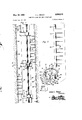
COMBINED CLAMP AND WELL SCRATCHER Filed June 10, 1957 2 Sheets-Sheet 1 Fig.
Alton L. .Seago I N V EN TOR.
May 10, 1960 A. SEAGO 2,935,031
COMBINED CLAMP AND WELL SCRATCHER Filed June 10, 1957 2 Sheets-Sheet 2 I N V EN TOR.
BY WM Mm,
8 6 a 8 m x a 2 4 2 7 n I u n w? 6 u u w N\ A 4 v H V H HI g r A 2 8 4 w 0 4 M 6 w United States Patent COMBINED CLAMP AND WELL SCRATCHER Alton L. Seago, Houma, La., assignor of fifty percent to W. E. Carlton, Houma, La.
Application June 10, 1957, Serial No. 664,650
9 Claims. (Cl. 166-173) This invention relates to the general class of subsurface well tools for use in the cementing of wells and more particularly to a combined clamp and well scratcher.
In the well cementing operation it is important that the mud cake be removed from a portion of the well bore to ensure a proper bond between the formation wall and the cement being pumped down the casing string.
It is the primary object of the present invention to provide a combined clamp and well scratcher for attachment to drill pipe.
Another object is to provide a combined clamp and well scratcher which may bequickly installed or removed and motmted on pipes of diiferent sizes.
A further object is to provide a well scratcher and f clamp which is not permanently aflixed to the pipe and which may be easily removed therefrom.
.A still further object is to provide a contractible clamp for attaching well scratchers to drill pipe having a novel split collar body and gripping means.
These together with other objects and advantages which will become subsequently apparent reside in the details of construction and operation as more fully hereinafter described and claimed, reference being had to the accompanying drawings forming a part hereof, wherein like numerals refer to like parts throughout, and in which:
Figure 1 is an elevation showing the novel scratcher section;
Figure 2 is a sectional view taken substantially upon a plane passing along section line 2-2 of Figure 1;
Figure 3 is a sectional view taken substantially upon the plane of section line 3-3 of Figure 2 and shows the novel split annular collar and the gripping means in position on a well pipe;
Figure 4 is a detailed perspective view of the gripping elements showing the serrated gripping end surface; and
Figure 5 is an exploded group perspective view of the contractible clamp, the scratcher elements and scratcher retaining strip.
Referring now to the drawings by distinguishing reference numerals, it will be observed that the numeral designates generally the present contractible clamp which comprises a hinged annular collar 12 formed of two arcuate sections 14 and 16 hinged together as shown in Figure 5 of the drawings and having rounded upper and lower edges. The arcuate section 14 is provided with two axially aligned circumferential projections 18 and 20 at one end. The arcuate section 16 is provided with circumferential projection 22 on one end which is disposed intermediate of projections 18 and 20. The projections 18, 20, and 22 are each provided with a longitudinal opening which is positioned in axial alignment to receive hinge pin 24 thereby retaining arcuate sections 14 and 16 in hinged relationship. The arcuate section 14 is provided at the other end with a depressed portion '26 on the outer surface 28. The depressed portion 26 forms complementary lugs 30 and 32 separated by a mounted on a well pipe with the well bore shown in bore 38 extending inwardly from surface 28. The arcuate section 16 is provided with circumferentially extending apertured lugs 40 and 42 on the other end and is provided with a radial opening 44 at an intermediate position. The opening 44 is further provided with counterbore 45 extending inwardly from the outer surface 46 of the arcuate section 16. An arcuate tongue 48 provided with a circumferentially extending apertured lug 50 is disposed with the apertured lug 50 in axial alignment between the apertured lugs 42 and 40 on arcuate section 16 with a hinge pin 43 extending through lugs 40, 42, and 50. The arcuate tongue 48 is further provided with an inwardly extending threaded socket or bore 52. A
The present clamp may thereby be-installed without welding and, easily. removed without necessitating a cutting operation and reused in subsequent operations. Thecollar 12 contactsthe well pipe 82 by the slip segments or gripping elements 62 only, with the arcuate sections 14 and 1-6 and the arcuate tongue 48 retained in spaced relation to the pipe 82.
The foregoing is considered as illustrative only of the principles ofv the invention. Further, since numerous modifications and changes will readily occur to those skilled in the art, it is not desired to limit the invention to the exact construction and operation shown and described, and accordingly, all suitable modifications and equivalents may be resorted to, falling within the scope of the invention as claimed.
What is claimed as new is as follows:
1. A combination clamp and well scratcher for attachment to drill pipe comprising a hinged, sectional annular collar, latching means to retain the ends of said hinged annular collar in contracted relationship, drill pipe gripping means disposed radially in said collar and projecting inwardly, scratcher retaining strips positioned on said gripping means and held thereby within the confines of said collar and extending parallel with the longitudinal axis of the drill pipe, and scratcher elements secured to said scratcher retainer strips and projecting-radially outward for engagement with a Well bore.
I 2. The combination as'recited in claim 1 wherein said hinged annular collar comprises two arcuate hinged sections.
3. The combination of claim 2 wherein one section of .said collar is provided with an arcuate tongue hingedly connected thereto, and clamp screw means engaged with said tongue and the other section of the collar.
4. The combination as recited in claim 3 wherein the other section of said hinged annular collar is provided with a depressed portion adjacent the end thereof adjacent said arcuate tongue, and a transverse notch adjacent said depressed portion for receiving said clamp screw means.
5. The combination as recited in claim 4 wherein said hinged annular collar is provided with radial openings in diametrically opposed positions thereon, said drill pipe gripping means including gripping elements adjus'tably positioned within said openings, said gripping elements being provided with inwardly projectingheads having serrations on the face thereof to effectively grip the drill Pip 6. The combination as recited in claim 5 wherein said scratcher retainer strips are provided with openings for positioning over the heads of the gripping elements on at least two collars for mounting the strips on the drill pipe.
7. A combination clamp and well scratcher for attachment to drill pipe comprising an annular collar including two arcuate sections hingedly connected together, an arcuate tongue hinged to one of said arcuate sections and provided with a screw threaded socket extending inwardly in the free end thereof, the other of said arcuate sections provided with a recess portion adjacent the disjointed end thereof and further provided with a notch extending from the exterior surface of said arcuate section inwardly and aligned axially with said screw threaded socket, each of said arcuate sections provided with oppositely disposed radial openings, gripping elements se- 1 cured within said oppositely disposed radial openings with the gripping ends thereof projecting inwardly, scratcher retaining strips secured to said gripping elements on said gripping ends and extending parallel with the longitudinal axis of a drill pipe, scratcher elements attached to said scratcher retaining strip and projecting outwardly, and
screw retaining-means received by said screw threaded opening with the head thereof retained adjacent said notch whereby said split annular collar is secured to a drill pipe.
8. A scratcher assembly for well bores comprising a length of drill pipe having a plurality of collars clamped thereto inlongitudinally spaced relation along said drill pipe, a pair of opposed gripper elements carried by each collar and projecting inwardly thereof to contact the drill pipe and-space adjacent portions of the collars therefrom, a stripextending between each adjacent pair of said collars and each strip having openings in its opposite ends receiving one gripper element in each associated adjacent pair of collars to hold and anchor the strips in place, and a plurality of scratcher elements fixed to each strip and projecting outwardly therefrom to engage a well bore.
9. An assembly for scratching well bores, comprising a length of drill pipe, a plurality of transversely split, hinged-collars clampingly engaged around said drill pipe at spaced points therealong, apair of gripper elements fixed thereto including head portions on the inner sides ofsaid collars spacing adjacent portions of the collars from the drill pipe, a plurality of strips lying along said pipe with successive strips lying on opposite sides of the pipe and extending between successive adjacent pairs of collars, each strip having openings through its opposite ends receiving the head portions of corresponding gripping elements to anchor the strips between corresponding adjacent pairs of collars,
' and a plurality of scratcher rods carried by said strips projecting therefrom for engagement with a well bore.
References Cited in the file of this patent UNITED STATES PATENTS each of said collars having
Priority Applications (1)
| Application Number | Priority Date | Filing Date | Title |
|---|---|---|---|
| US664650A US2936031A (en) | 1957-06-10 | 1957-06-10 | Combined clamp and well scratcher |
Applications Claiming Priority (1)
| Application Number | Priority Date | Filing Date | Title |
|---|---|---|---|
| US664650A US2936031A (en) | 1957-06-10 | 1957-06-10 | Combined clamp and well scratcher |
Publications (1)
| Publication Number | Publication Date |
|---|---|
| US2936031A true US2936031A (en) | 1960-05-10 |
Family
ID=24666862
Family Applications (1)
| Application Number | Title | Priority Date | Filing Date |
|---|---|---|---|
| US664650A Expired - Lifetime US2936031A (en) | 1957-06-10 | 1957-06-10 | Combined clamp and well scratcher |
Country Status (1)
| Country | Link |
|---|---|
| US (1) | US2936031A (en) |
Cited By (5)
| Publication number | Priority date | Publication date | Assignee | Title |
|---|---|---|---|---|
| US20080145139A1 (en) * | 2004-08-24 | 2008-06-19 | Specialised Petroleum Services Group Limited | Clamp |
| US20110108278A1 (en) * | 2009-04-28 | 2011-05-12 | Katch Kan Holdings Ltd. | Apparatus and method for stripping solids and fluids from a string used in drilling or servicing wells |
| US20110265988A1 (en) * | 2010-05-03 | 2011-11-03 | Baker Hughes Incorporated | Wellbore Cleaning Devices |
| US20160177641A1 (en) * | 2014-12-18 | 2016-06-23 | Katch Kan Holdings Ltd. | Well fluid containment device with safety mechanism |
| US9784065B2 (en) | 2014-01-27 | 2017-10-10 | Katch Kan Holdings Ltd. | Apparatus and method for stripping solids and fluids from a string used in drilling or servicing wells |
Citations (3)
| Publication number | Priority date | Publication date | Assignee | Title |
|---|---|---|---|---|
| US1731128A (en) * | 1927-07-11 | 1929-10-08 | John W Edwards | Pipe-lifting device |
| US2229607A (en) * | 1939-12-13 | 1941-01-21 | Harry B Poist | Self-adjustable clamping spider and the like |
| US2735494A (en) * | 1956-02-21 | Fflnge for well scratcher |
-
1957
- 1957-06-10 US US664650A patent/US2936031A/en not_active Expired - Lifetime
Patent Citations (3)
| Publication number | Priority date | Publication date | Assignee | Title |
|---|---|---|---|---|
| US2735494A (en) * | 1956-02-21 | Fflnge for well scratcher | ||
| US1731128A (en) * | 1927-07-11 | 1929-10-08 | John W Edwards | Pipe-lifting device |
| US2229607A (en) * | 1939-12-13 | 1941-01-21 | Harry B Poist | Self-adjustable clamping spider and the like |
Cited By (10)
| Publication number | Priority date | Publication date | Assignee | Title |
|---|---|---|---|---|
| US20080145139A1 (en) * | 2004-08-24 | 2008-06-19 | Specialised Petroleum Services Group Limited | Clamp |
| US8388256B2 (en) | 2004-08-24 | 2013-03-05 | Specialised Petroleum Services Group Limited | Clamp |
| US9410570B2 (en) | 2004-08-24 | 2016-08-09 | Specialised Petroleum Services Group Limited | Clamp |
| US20110108278A1 (en) * | 2009-04-28 | 2011-05-12 | Katch Kan Holdings Ltd. | Apparatus and method for stripping solids and fluids from a string used in drilling or servicing wells |
| US20110265988A1 (en) * | 2010-05-03 | 2011-11-03 | Baker Hughes Incorporated | Wellbore Cleaning Devices |
| US8511375B2 (en) * | 2010-05-03 | 2013-08-20 | Baker Hughes Incorporated | Wellbore cleaning devices |
| US9784065B2 (en) | 2014-01-27 | 2017-10-10 | Katch Kan Holdings Ltd. | Apparatus and method for stripping solids and fluids from a string used in drilling or servicing wells |
| US10107063B2 (en) | 2014-01-27 | 2018-10-23 | Katch Kan Holdings Ltd. | Apparatus and method for stripping solids and fluids from a string used in drilling or servicing wells |
| US20160177641A1 (en) * | 2014-12-18 | 2016-06-23 | Katch Kan Holdings Ltd. | Well fluid containment device with safety mechanism |
| US10294740B2 (en) * | 2014-12-18 | 2019-05-21 | Katch Kan Holdings Ltd. | Well fluid containment device with safety mechanism |
Similar Documents
| Publication | Publication Date | Title |
|---|---|---|
| US2855052A (en) | Stop collar for a well pipe | |
| US4139023A (en) | Pipe thread protector | |
| US2986417A (en) | Stop devices for well conduits | |
| US4042023A (en) | Control line protector | |
| US4000549A (en) | Stabilizer | |
| US2962313A (en) | Stop ring for well conduit | |
| US2824613A (en) | Stop devices for well conduits | |
| US4101179A (en) | Drilling stabilizer including mechanical interlock device | |
| US5699867A (en) | Bit retention device for a bit and chuck assembly of a down-the-hole, percussive drill | |
| US2714932A (en) | Bridging plug | |
| US2797756A (en) | Well tool mounting | |
| US4258804A (en) | Releasable drill string stabilizer | |
| US2739018A (en) | Split sleeve and method of making the same | |
| US4384626A (en) | Clamp-on stabilizer | |
| US2718266A (en) | Stop devices for well conduits | |
| US4011918A (en) | Stabilizer for drill strings | |
| US4139059A (en) | Well casing hanger assembly | |
| US2368415A (en) | Drill pipe protector | |
| US2936031A (en) | Combined clamp and well scratcher | |
| US2628682A (en) | Centering and well cleaning tool | |
| US3125382A (en) | Well tools | |
| JPS5857600B2 (en) | Pipe protector used for oil well drill pipes, etc. | |
| US2513621A (en) | Tool joint wear collar | |
| US2482962A (en) | Tool joint wear collar | |
| US3094360A (en) | Split protector for well pipe |