US2934026A - Tamping implement - Google Patents
Tamping implement Download PDFInfo
- Publication number
- US2934026A US2934026A US600124A US60012456A US2934026A US 2934026 A US2934026 A US 2934026A US 600124 A US600124 A US 600124A US 60012456 A US60012456 A US 60012456A US 2934026 A US2934026 A US 2934026A
- Authority
- US
- United States
- Prior art keywords
- handle
- tamping
- housing
- implement
- vibrator
- Prior art date
- Legal status (The legal status is an assumption and is not a legal conclusion. Google has not performed a legal analysis and makes no representation as to the accuracy of the status listed.)
- Expired - Lifetime
Links
Images
Classifications
-
- E—FIXED CONSTRUCTIONS
- E01—CONSTRUCTION OF ROADS, RAILWAYS, OR BRIDGES
- E01B—PERMANENT WAY; PERMANENT-WAY TOOLS; MACHINES FOR MAKING RAILWAYS OF ALL KINDS
- E01B27/00—Placing, renewing, working, cleaning, or taking-up the ballast, with or without concurrent work on the track; Devices therefor; Packing sleepers
- E01B27/12—Packing sleepers, with or without concurrent work on the track; Compacting track-carrying ballast
- E01B27/13—Packing sleepers, with or without concurrent work on the track
- E01B27/14—Manual tools or hand-held power tools therefor
Definitions
- This invention relates to a vibrating implement and more particularly is concerned with a vibratory tamping implement adapted for tamping the ballast of railway beds.
- Railway tie-tamping tools usually comprise a tamper blade which is pulsated by means of an unbalanced vibrator.
- the vibratory mo- .tions of the vibrator are also transmitted to the handlebars of the implement.
- the operator is subjected .to the strain of the vibration.
- the lateral components of the vibrating forces are transmitted to the ;tamplng blade, thus subjecting it to undue wear.
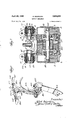
- Fig. 1 is a perspective view of the tamping implement of the invention
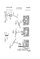
- Fig. 2 is a schematic representation of the tamping instrument of the invention, indicating the principle of operation of the double pendulum system
- Fig. 3 is a cross-sectional view taken along line 3-3 of Fig. 1,
- Figs. 4-6 are elevational views of the tamping instrument of the invention, illustrating several successive tietamping positions
- Fig. 7 is a cross-sectional view through the vibrator housing, showing details of the elastic joints.
- an elastic joint is interposed between the handle and the unbalanced vibrator a position adjacent the vibrator housing.
- the axis of the elastic joint is located substantially parallel to the axis of rotation of the unbalanced vibrator.
- the elastic joint being thus mounted, creates a double pendulum system, i.e. circular vibratory movements tend to fulcrum about the handle-bar end of the handle, and about the working end of the tamping blade.
- This elastic joint effectively dampens out the lateral components of the circular vibratory motion so that substantially only vertical components'of such vibrations are transmitted to the end of the
- the axis of rotation of the unbalanced vibrator is therefore disposed substantially parallel to the plane of the tamping blade, which is rigidly attached to the vibrator housing.
- the invention includes a provision for elastically attach- 2,934,026 Patented Apr. 26, 1960 ing the handle-bars to the handle so that these vertically directed vibrational components are dampened out, and substantially no vibratory motion is transmitted to the grips at the handle-bar ends.
- the operator can effectively guide and conveniently manipulate the tamping implement with a minimum of fatigue.
- the handle-bars are both pivotally and adjustably connected to the handle, the handle-bars can be so adjusted and clamped that they will always be substantially perpendicular to the handle in the various working positions of the tamping tool. The operator therefore can maintain a normal working position while guiding the tool straight down even though the tamping blade be inserted underneath a tie.
- the tamping implement comprises a tamping blade 101 which is attached to the housing of an unbalanced vibrator 102.
- the rotary shaft 102' (see Fig. 2) of the unbalanced vibrator is arranged substantially parallel to the plane of the tamping blade 101.
- the unbalanced vibrator 102 is connected by means of an elastic joint 103 to a handle 104.
- handle-bars 107, 107' At the upper end of the handle are attached the handle-bars 107, 107'. Rubber handle grips 106, 106' are mounted at the end of the handle-bars, as shown in Fig. 1.
- Fig. 2 clearly indicates the double pendulum system of the tamping implement.
- the working end 101' of the tamping blade 101, and the point 104' of jointure of the handle-bars 107, 107' to the handle, can be considered as fulcrum points.
- the unbalanced vibrator 102 therefore, tends to rotate the vibrator implement about each one of these fulcrum points, as indicated by the dot and dash lines in Fig. 2.
- the elastic joint 103 acts to dampen these horizontally directed vibration components so that only vertically directed components of vibration are transmitted to the tamping blade 101 and to the handle 104.
- FIG. 3 clearly shows the structure of an elastic joint 108 in which metal plates 109, 109' are bonded at their inner surfaces to a rubber member 110.
- the inner plate 109' is welded to the plate 105.
- the tamping implement can assume various tamping positions as it proceeds to tamp the ballast firmly and densely under the ties.
- Figs. 4-6 show the successive positions A, B and C assumed by the tamping implement in operation as it proceeds to tamp the ballast beneath a tie.
- position A the position of the tie
- position C the position of the tamping blade
- the tamping implement of the invention may be used upon ties made of timber, steel or concrete, and both newly laid and old consolidated ballasts can be tamped with ease.
- the ballast need not be loosened or removed for purposes of tamping.
- the handle 104 is bifurcated.
- the handle is attached to the vibrator housing by elastic joints 103, 103 (see Fig. 7).
- elastic joints 103, 103 In the lower ends 9, 9 of the bifurcated handle 104 are clamped to pins 5, 5', against relative rotational movement.
- Mounted upon the inner end of each of the pins 5, 5' is a semi-rigid torsion spring. Since both elastic joints 103 are identical, the details of only one of these is described vhereinafter.
- the pin 5 consists of an inner tapered portion 5a, fol:
- the torsionspring includes the elastic rotary member 7, e.g. made of rubber, which has bonded to its outer surface a metal ring 8, and bonded to its inner surface a metal ring 15.
- a tapered bushing or gripping sleeve 20 is mounted on the tapered portion 5a of pin 5 and held in engagement therewith by the nut.
- the outer ring 8 is clamped to the housingby means of bolted ears 11.
- the vibrator 102 comprises an electric motor 21 having a motor shaft 102' upon which a series of weights are mounted.
- the position of the weights 4, 4 can be adjusted to control the magnitude of the unbalanced forces. Readyaccess to these eccentric weights is obtained by removal of the cover plates 3, 3, and loosening of the cotter pins, 18, 18.
- the implement may be used for digging or stamping, by simply replacing the tamping blade with a digging or stamping implement.
- An implement comprising a housing, an unbalanced vibrator disposed within said housing comprising a shaft having an unbalancing weight affixed thereto for rotation about the axis of said shaft and means for rotating said shaft, a substantially planar tool affixed to the lower end of said housing, an elongated handle member, a semirigid torsion joint pivotally connecting said handle member with said housing for elastically restrained pivotal movement about the axis of said torsion joint, said torsion joint comprising a pin having one portion thereof journalled for rotational movement in said housing and having one end of saidpin rigidly alfixed to said handle member and a cylindrical torsion spring means mounted about said pin for biasing said pin toward-a normal rest position with respect to said housing, the inner surface of said torsion spring being rigidly aflixed to said pin and the outer surface of said torsion spring means being rigidly aflixed to said housing, the axis of said pin being disposed substantially perpendicular to the handle member and substantially parallel both to
- said semi-rigid torsion joint comprises a pin journaled in said housing and a cylindrical elastic member, said handle being rigidly afiixed to said pin to rotate therewith, said cylindrical elastic member being fixedly mounted on said pin, and said elastic member being aflixed on its outer surface against rotation with respect to said housing.
- each of said semi-rigid torsion joints comprises a pair of axially aligned pins and a pair of cylindrical elastic members, the furcations of said handle being clamped each to a separate pin, said elastic members being mounted each on a separate pin and each affixed at its inner surface against rotation with respect to its respective pin, and said elastic members being afiixedon their outer surfaces against rotation with respect to said housing.
- each of said semirigid torsion joints includes, in addition, an inner and an outer metal ring for each of said elastic members bonded thereto at their outer and inner cylindrical surfaces, respectively, said outer metal ring being aflixed against rotation with respect to said housing and said inner ring being aflixed against rotation with respect to said pin.
- a tamping implement comprising a housing, an unbalanced vibrator disposed within said housing comprising a shaft having an unbalancing Weight affixed thereto for rotation about the axis of said shaft and means for rotating said shaft, a substantially planar tamping tool aiiixed to the lower end of said housing, an elongated handle member having a pair of handle bars each transversely arranged at one end thereof of said handle member and extending in opposite directions therefrom, a semi-rigid torsion joint pivotally connecting the other end of said handle member with said housing for elastically restrained pivotal movement about the axis of said torsion joint, said torsion joint comprising a pin journaled within said housing, and a cylindrical elastic member, said handle being affixed to said pin to rotate therewith, said cylindrical elastic member being fixedly mounted on said pin, and being affixed on its outer surface against rotation with respect to said housing, the axis of said pin being disposed substantially perpendicular to the handle member and substantially
- a tamping implement comprising a housing, an unbalanced vibrator comprising a shaft having an unbalancing weight afiixed thereto journaled within said housing for rotating about an axis and means for rotating said shaft, a generally planar tamping tool rigidly affixed to said housing, an elongated handle pivotally connected at one endtthereof to said housing for pivotal movement about an axis parallel to the axis of said vibrator, elastic means for restraining such pivotal movement and effecting a semi-rigid pivot connection of said handle with said housing, said elastic means comprising a cylindrical elastic member the outer surface of which is afiixed against rotation with respect to said housing and the axis of which is affixed against rotation with respect to said handle, a pair of handle-bars extending respectively in opposite directions transversely of said handle at the other end thereof and perpendicular to said axis of said vibrator, each said handle-bar being attached to said handle by a flexible coupling and
- said semi-rigid joint adapted to connect the lower end of said handle to said housing, said semi-rigid joint comprising a pin having one portion thereof journaled for rotational movement in said housing and having one end of said pin rigidly afiixed to said handle member and a cylindrical torsion spring means mounted about said pin for biasing said pin toward a normal rest position with respect to said housing, the inner surface of said torsion spring means being rigidly afiixed to said pin and the outer surface of said torsion spring means being rigidly afiixed to said housing, said semi-rigid joint transmitting vibratory movement to cause lateral vibration of said handle about the upper end thereof as a pivot point and longitudinal vibration of said handle as a whole, the second part or" said system comprising an elastic joint adapted to connect the top end of handle with an end of each part of the handle-bar, said elastic joint adapted to transmit longitudinal vibratory movement of said handle 6 to cause lateral vibration of the handle-bars about the grips thereon at the
Description
April 26, 1960 K. BEIERLEIN TAMPING IMPLEMENT 2 Sheets-Sheet 1 Filed July 25, 1956 April 26, 1960 K. BEIERLEIN TAMPING IMPLEMENT- 2 Sheets-Sheet 2 Filed July 25, 1956 tamping blade and to the end of the handle.
iUited States atent O TAMPING IMPLEMENT Karl Beierlein, Dusseldorf-Grafenberg, Germany Application July 25, 1956, Serial No. 600,124
Claims priority, application Germany April 9, 1952 7 Claims. (Cl. 104-13) This application is a continuation-in-part of my prior US. application Serial No. 347,896, filed on April 10, 1953, now abandoned.
This invention relates to a vibrating implement and more particularly is concerned with a vibratory tamping implement adapted for tamping the ballast of railway beds.
Railway tie-tamping tools usually comprise a tamper blade which is pulsated by means of an unbalanced vibrator. In such tie-tamping implements the vibratory mo- .tions of the vibrator are also transmitted to the handlebars of the implement. Thus, the operator, is subjected .to the strain of the vibration. Also, the lateral components of the vibrating forces are transmitted to the ;tamplng blade, thus subjecting it to undue wear.
It is accordingly one object of this invention to pro vide a tamping implement in which the vibrator trans- ,rnits only vertical components of vibrations to both the tamping blade and the handle of the implement. It is another object of the invention to provide a handle mounting structure for a tamping implement which substantially dampens out the vertical components of the vibratory pulsations of the vibrator. Other advantages and objects of the invention will become readily apparent upon a reading of the description following hereinafter and upon an examination of the accompanying drawings in which:
Fig. 1 is a perspective view of the tamping implement of the invention,
Fig. 2 is a schematic representation of the tamping instrument of the invention, indicating the principle of operation of the double pendulum system,
Fig. 3 is a cross-sectional view taken along line 3-3 of Fig. 1,
Figs. 4-6 are elevational views of the tamping instrument of the invention, illustrating several successive tietamping positions, and
Fig. 7 is a cross-sectional view through the vibrator housing, showing details of the elastic joints.
According to the invention, an elastic joint, is interposed between the handle and the unbalanced vibrator a position adjacent the vibrator housing. The axis of the elastic joint is located substantially parallel to the axis of rotation of the unbalanced vibrator. The elastic joint being thus mounted, creates a double pendulum system, i.e. circular vibratory movements tend to fulcrum about the handle-bar end of the handle, and about the working end of the tamping blade. This elastic joint effectively dampens out the lateral components of the circular vibratory motion so that substantially only vertical components'of such vibrations are transmitted to the end of the The axis of rotation of the unbalanced vibrator is therefore disposed substantially parallel to the plane of the tamping blade, which is rigidly attached to the vibrator housing.
Since the vibrations on the handle-bar end of the handle are substantially only vertically directed vibrations, the invention includes a provision for elastically attach- 2,934,026 Patented Apr. 26, 1960 ing the handle-bars to the handle so that these vertically directed vibrational components are dampened out, and substantially no vibratory motion is transmitted to the grips at the handle-bar ends. Thus, the operator can effectively guide and conveniently manipulate the tamping implement with a minimum of fatigue. Also, since the handle-bars are both pivotally and adjustably connected to the handle, the handle-bars can be so adjusted and clamped that they will always be substantially perpendicular to the handle in the various working positions of the tamping tool. The operator therefore can maintain a normal working position while guiding the tool straight down even though the tamping blade be inserted underneath a tie.
As indicated in Fig. 1, the tamping implement comprises a tamping blade 101 which is attached to the housing of an unbalanced vibrator 102. The rotary shaft 102' (see Fig. 2) of the unbalanced vibrator is arranged substantially parallel to the plane of the tamping blade 101. The unbalanced vibrator 102 is connected by means of an elastic joint 103 to a handle 104. At the upper end of the handle are attached the handle-bars 107, 107'. Rubber handle grips 106, 106' are mounted at the end of the handle-bars, as shown in Fig. 1.
Fig. 2 clearly indicates the double pendulum system of the tamping implement. The working end 101' of the tamping blade 101, and the point 104' of jointure of the handle-bars 107, 107' to the handle, can be considered as fulcrum points. The unbalanced vibrator 102, therefore, tends to rotate the vibrator implement about each one of these fulcrum points, as indicated by the dot and dash lines in Fig. 2. However, the elastic joint 103 acts to dampen these horizontally directed vibration components so that only vertically directed components of vibration are transmitted to the tamping blade 101 and to the handle 104.
As indicated in Fig. l the handle- bars 107, 107, 107', 107' are mounted upon plates 105, by means of elastic joints 108. Fig. 3 clearly shows the structure of an elastic joint 108 in which metal plates 109, 109' are bonded at their inner surfaces to a rubber member 110. The inner plate 109' is welded to the plate 105. Thus, the vertically directed vibration components upon reaching the plate 104 are effectively dampened out by the elastic joint 108 so that the grip members 106, 106' are substantially free from any vibration.
In view of the nature of the elastic joint 103, the tamping implement can assume various tamping positions as it proceeds to tamp the ballast firmly and densely under the ties. Figs. 4-6 show the successive positions A, B and C assumed by the tamping implement in operation as it proceeds to tamp the ballast beneath a tie. Thus, while the tamping implement is inserted almost vertically (position A), after reaching the lower edge of the tie, it is inclined as shown in position B and finally assumes the position shown as position C in Fig. 6, when the heel of the tamping blade goes right under the tie, with the edge of the tamping blade being positioned almost horizontally beneath the tie. The tamping implement of the invention may be used upon ties made of timber, steel or concrete, and both newly laid and old consolidated ballasts can be tamped with ease. The ballast need not be loosened or removed for purposes of tamping.
As indicated in Fig. 1, the handle 104 is bifurcated. The handle is attached to the vibrator housing by elastic joints 103, 103 (see Fig. 7). In the lower ends 9, 9 of the bifurcated handle 104 are clamped to pins 5, 5', against relative rotational movement. Mounted upon the inner end of each of the pins 5, 5' is a semi-rigid torsion spring. Since both elastic joints 103 are identical, the details of only one of these is described vhereinafter. The pin 5 consists of an inner tapered portion 5a, fol:
lowed by an enlarged bearing portion 55 and a shoulder 5c. A retaining ring 19 holds the bearing 17 within the housing portion 6. The torsionspring includes the elastic rotary member 7, e.g. made of rubber, which has bonded to its outer surface a metal ring 8, and bonded to its inner surface a metal ring 15. A tapered bushing or gripping sleeve 20 is mounted on the tapered portion 5a of pin 5 and held in engagement therewith by the nut. The outer ring 8 is clamped to the housingby means of bolted ears 11. Thus, when the lower end 9 of the handle 104 is fixed to pin 5 in a rigid manner, this rigid connection extends up to the inner ring 15 of the torsion spring. Thus, when the vibrator tends to transmit lateral vibrations under the double pendulum system described above, these vibrations are dampened out by the torsion springs, i.e. the twisting movements of the rotary members 7;
The vibrator 102 comprises an electric motor 21 having a motor shaft 102' upon which a series of weights are mounted. The position of the weights 4, 4 can be adjusted to control the magnitude of the unbalanced forces. Readyaccess to these eccentric weights is obtained by removal of the cover plates 3, 3, and loosening of the cotter pins, 18, 18.
Although I have illustrated and described only one embodiment of the invention, it is readily apparent that embodiments or adaptations may be made within the scope of the invention. Thus, the implement may be used for digging or stamping, by simply replacing the tamping blade with a digging or stamping implement.
The. invention claimed is:
1. An implement comprising a housing, an unbalanced vibrator disposed within said housing comprising a shaft having an unbalancing weight affixed thereto for rotation about the axis of said shaft and means for rotating said shaft, a substantially planar tool affixed to the lower end of said housing, an elongated handle member, a semirigid torsion joint pivotally connecting said handle member with said housing for elastically restrained pivotal movement about the axis of said torsion joint, said torsion joint comprising a pin having one portion thereof journalled for rotational movement in said housing and having one end of saidpin rigidly alfixed to said handle member and a cylindrical torsion spring means mounted about said pin for biasing said pin toward-a normal rest position with respect to said housing, the inner surface of said torsion spring being rigidly aflixed to said pin and the outer surface of said torsion spring means being rigidly aflixed to said housing, the axis of said pin being disposed substantially perpendicular to the handle member and substantially parallel both to the axis of said vibrator shaft and to the plane of the tool, whereby torsional vibrational components at said joint are substantially dampened out and longitudinal vibrational components perpendicular to said joint axis are transmitted to said tool and to said handle member.
2. The implement of claim 1 wherein said semi-rigid torsion joint comprises a pin journaled in said housing and a cylindrical elastic member, said handle being rigidly afiixed to said pin to rotate therewith, said cylindrical elastic member being fixedly mounted on said pin, and said elastic member being aflixed on its outer surface against rotation with respect to said housing.
3. The implement of claim 1 wherein said handle is bifurcated at its lower end, eachv of said furcations being connected to said housing by a semi-rigid torsion joint; each of said semi-rigid torsion joints comprises a pair of axially aligned pins and a pair of cylindrical elastic members, the furcations of said handle being clamped each to a separate pin, said elastic members being mounted each on a separate pin and each affixed at its inner surface against rotation with respect to its respective pin, and said elastic members being afiixedon their outer surfaces against rotation with respect to said housing.
4. The implement of claim 3 wherein each of said semirigid torsion joints includes, in addition, an inner and an outer metal ring for each of said elastic members bonded thereto at their outer and inner cylindrical surfaces, respectively, said outer metal ring being aflixed against rotation with respect to said housing and said inner ring being aflixed against rotation with respect to said pin.
5. A tamping implement comprising a housing, an unbalanced vibrator disposed within said housing comprising a shaft having an unbalancing Weight affixed thereto for rotation about the axis of said shaft and means for rotating said shaft, a substantially planar tamping tool aiiixed to the lower end of said housing, an elongated handle member having a pair of handle bars each transversely arranged at one end thereof of said handle member and extending in opposite directions therefrom, a semi-rigid torsion joint pivotally connecting the other end of said handle member with said housing for elastically restrained pivotal movement about the axis of said torsion joint, said torsion joint comprising a pin journaled within said housing, and a cylindrical elastic member, said handle being affixed to said pin to rotate therewith, said cylindrical elastic member being fixedly mounted on said pin, and being affixed on its outer surface against rotation with respect to said housing, the axis of said pin being disposed substantially perpendicular to the handle member and substantially parallel both to the axis of said vibrator shaft and to the plane of the tool, whereby torsional vibrational components at said joint are substantially dampened out and longitudinal vibrational components perpendicular to said joint axis are transmitted to said tool and to said handle member, said handle-bars being connected to said handle. member solely by a flexible joint, whereby the vibrational components transmitted along said handle member are substantially damped out at said flexible joint and the free end of each handle-bar is substantially free from vibration.
6. A tamping implement comprising a housing, an unbalanced vibrator comprising a shaft having an unbalancing weight afiixed thereto journaled within said housing for rotating about an axis and means for rotating said shaft, a generally planar tamping tool rigidly affixed to said housing, an elongated handle pivotally connected at one endtthereof to said housing for pivotal movement about an axis parallel to the axis of said vibrator, elastic means for restraining such pivotal movement and effecting a semi-rigid pivot connection of said handle with said housing, said elastic means comprising a cylindrical elastic member the outer surface of which is afiixed against rotation with respect to said housing and the axis of which is affixed against rotation with respect to said handle, a pair of handle-bars extending respectively in opposite directions transversely of said handle at the other end thereof and perpendicular to said axis of said vibrator, each said handle-bar being attached to said handle by a flexible coupling and having a hand grip at the distal end thereof, the construction and arrangement being such that rotary vibration of said housing causes lateral vibration of said handle about the end thereof attached to said handle-bars as a pivot point and longitudinal vibration of said handle as a whole and such longitudinal vibration of said handle causes lateral vibration of the respective handle-bars about the grips at the ends thereof attached to said handle as pivot points, whereby said grips on said handle-bars are substantially free from vibration due to vibration of said vibrator.
prisinga semi-rigid joint adapted to connect the lower end of said handle to said housing, said semi-rigid joint comprising a pin having one portion thereof journaled for rotational movement in said housing and having one end of said pin rigidly afiixed to said handle member and a cylindrical torsion spring means mounted about said pin for biasing said pin toward a normal rest position with respect to said housing, the inner surface of said torsion spring means being rigidly afiixed to said pin and the outer surface of said torsion spring means being rigidly afiixed to said housing, said semi-rigid joint transmitting vibratory movement to cause lateral vibration of said handle about the upper end thereof as a pivot point and longitudinal vibration of said handle as a whole, the second part or" said system comprising an elastic joint adapted to connect the top end of handle with an end of each part of the handle-bar, said elastic joint adapted to transmit longitudinal vibratory movement of said handle 6 to cause lateral vibration of the handle-bars about the grips thereon at the distal ends thereof as pivot points, whereby transmission of vibration from said housing to said handle-bar grips is prevented in two stages, one stage being efieeted by each part of the two-part connection system.
References Cited in the file of this patent UNITED STATES PATENTS 1,341,945 Study June 1, 1920 1,706,575 Jackson Mar. 26, 1929 1,741,240 Jackson Dec. 31, 1929 2,137,842 Jackson Nov. 22, 1938 2,203,342 Sloman June 4, 1940 2,286,609 Ledwinka June 16, 1942 2,690,335 Ballard Sept. 28, 1954
Applications Claiming Priority (1)
| Application Number | Priority Date | Filing Date | Title |
|---|---|---|---|
| DE2934026X | 1952-04-09 |
Publications (1)
| Publication Number | Publication Date |
|---|---|
| US2934026A true US2934026A (en) | 1960-04-26 |
Family
ID=8001691
Family Applications (1)
| Application Number | Title | Priority Date | Filing Date |
|---|---|---|---|
| US600124A Expired - Lifetime US2934026A (en) | 1952-04-09 | 1956-07-25 | Tamping implement |
Country Status (1)
| Country | Link |
|---|---|
| US (1) | US2934026A (en) |
Cited By (11)
| Publication number | Priority date | Publication date | Assignee | Title |
|---|---|---|---|---|
| DE1216808B (en) * | 1964-10-28 | 1966-05-12 | Wacker Hermann | Arrangement for damping the transmission of bumps, bumps or vibrations when operating a bump, bump or vibration-generating motor-operated equipment, e.g. B. Hammer or tamper |
| US3396671A (en) * | 1966-02-21 | 1968-08-13 | Jackson Vibrators | Adjustable tamper blade assembly |
| JPS5275211U (en) * | 1975-11-27 | 1977-06-04 | ||
| JPS52119607U (en) * | 1976-03-08 | 1977-09-10 | ||
| JPS5391105U (en) * | 1976-12-27 | 1978-07-26 | ||
| JPS5413105U (en) * | 1977-06-28 | 1979-01-27 | ||
| JPS5488706U (en) * | 1977-12-05 | 1979-06-23 | ||
| US4323014A (en) * | 1980-01-17 | 1982-04-06 | Nippon Kokuyu Tetsudo | Tie tamper |
| US4327645A (en) * | 1979-08-27 | 1982-05-04 | Nippon Kokuyu Tetsudo | Tie tamper |
| CN101892618A (en) * | 2010-07-02 | 2010-11-24 | 重庆运达机电设备制造有限公司 | Portable centrifugal internal combustion tamping pick |
| WO2012097960A1 (en) * | 2011-01-19 | 2012-07-26 | Robel Bahnbaumaschinen Gmbh | A hand packer for packing a track |
Citations (7)
| Publication number | Priority date | Publication date | Assignee | Title |
|---|---|---|---|---|
| US1341945A (en) * | 1919-12-23 | 1920-06-01 | Nathaniel C Study | Tamper and the like implement |
| US1706575A (en) * | 1927-12-10 | 1929-03-26 | Jackson Corwill | Tamper or like impact tool |
| US1741240A (en) * | 1928-09-29 | 1929-12-31 | Jackson Corwill | Tamping and like implement |
| US2137842A (en) * | 1935-10-28 | 1938-11-22 | Jackson Corwill | Ballast working implement |
| US2203342A (en) * | 1937-09-30 | 1940-06-04 | Briggs Mfg Co | Spring device |
| US2286609A (en) * | 1940-05-17 | 1942-06-16 | Budd Edward G Mfg Co | Wheel suspension for vehicles |
| US2690335A (en) * | 1952-01-30 | 1954-09-28 | Firestone Tire & Rubber Co | Rubber spring |
-
1956
- 1956-07-25 US US600124A patent/US2934026A/en not_active Expired - Lifetime
Patent Citations (7)
| Publication number | Priority date | Publication date | Assignee | Title |
|---|---|---|---|---|
| US1341945A (en) * | 1919-12-23 | 1920-06-01 | Nathaniel C Study | Tamper and the like implement |
| US1706575A (en) * | 1927-12-10 | 1929-03-26 | Jackson Corwill | Tamper or like impact tool |
| US1741240A (en) * | 1928-09-29 | 1929-12-31 | Jackson Corwill | Tamping and like implement |
| US2137842A (en) * | 1935-10-28 | 1938-11-22 | Jackson Corwill | Ballast working implement |
| US2203342A (en) * | 1937-09-30 | 1940-06-04 | Briggs Mfg Co | Spring device |
| US2286609A (en) * | 1940-05-17 | 1942-06-16 | Budd Edward G Mfg Co | Wheel suspension for vehicles |
| US2690335A (en) * | 1952-01-30 | 1954-09-28 | Firestone Tire & Rubber Co | Rubber spring |
Cited By (20)
| Publication number | Priority date | Publication date | Assignee | Title |
|---|---|---|---|---|
| DE1216808B (en) * | 1964-10-28 | 1966-05-12 | Wacker Hermann | Arrangement for damping the transmission of bumps, bumps or vibrations when operating a bump, bump or vibration-generating motor-operated equipment, e.g. B. Hammer or tamper |
| US3396671A (en) * | 1966-02-21 | 1968-08-13 | Jackson Vibrators | Adjustable tamper blade assembly |
| JPS5275211U (en) * | 1975-11-27 | 1977-06-04 | ||
| JPS5443442Y2 (en) * | 1975-11-27 | 1979-12-15 | ||
| JPS52119607U (en) * | 1976-03-08 | 1977-09-10 | ||
| JPS5634004Y2 (en) * | 1976-03-08 | 1981-08-12 | ||
| JPS5391105U (en) * | 1976-12-27 | 1978-07-26 | ||
| JPS59323Y2 (en) * | 1976-12-27 | 1984-01-07 | 芝浦メカトロニクス株式会社 | Taitampa |
| JPS5750332Y2 (en) * | 1977-06-28 | 1982-11-04 | ||
| JPS5413105U (en) * | 1977-06-28 | 1979-01-27 | ||
| JPS5488706U (en) * | 1977-12-05 | 1979-06-23 | ||
| JPS5750333Y2 (en) * | 1977-12-05 | 1982-11-04 | ||
| US4327645A (en) * | 1979-08-27 | 1982-05-04 | Nippon Kokuyu Tetsudo | Tie tamper |
| US4323014A (en) * | 1980-01-17 | 1982-04-06 | Nippon Kokuyu Tetsudo | Tie tamper |
| CN101892618A (en) * | 2010-07-02 | 2010-11-24 | 重庆运达机电设备制造有限公司 | Portable centrifugal internal combustion tamping pick |
| WO2012097960A1 (en) * | 2011-01-19 | 2012-07-26 | Robel Bahnbaumaschinen Gmbh | A hand packer for packing a track |
| CN103314158A (en) * | 2011-01-19 | 2013-09-18 | 罗贝尔铁路建筑机械有限责任公司 | A hand packer for packing a track |
| JP2014503040A (en) * | 2011-01-19 | 2014-02-06 | ローベル バーンバウマシーネン ゲゼルシャフト ミット ベシュレンクテル ハフツング | Hand tie tamper for compaction with track |
| CN103314158B (en) * | 2011-01-19 | 2015-07-15 | 罗贝尔铁路建筑机械有限责任公司 | A hand packer for packing a track |
| AU2012208777B2 (en) * | 2011-01-19 | 2016-08-25 | Robel Bahnbaumaschinen Gmbh | A hand packer for packing a track |
Similar Documents
| Publication | Publication Date | Title |
|---|---|---|
| US2934026A (en) | Tamping implement | |
| JP4304545B2 (en) | Work implements operated by handgrip | |
| JP2001510099A (en) | Percussion hammer and / or drill hammer having vibration damping action | |
| US3367716A (en) | Sonic rectifier coupling for rock cutting apparatus | |
| EP0144392B1 (en) | Vibrating plate | |
| US20030175078A1 (en) | Vibration isolation for a percussion rammer | |
| US3275089A (en) | Handle means for percussive tool | |
| US4060138A (en) | Vibratory tools | |
| US5947211A (en) | Vibration-damped machine driven tool | |
| JPS59196176A (en) | Grip for working machine damping vibration | |
| EP0457740A1 (en) | A vibrator damped hand held rotary grinding machine | |
| Andersson | Design and testing of a vibration attenuating handle | |
| JPH0673826B2 (en) | Anti-vibration handle device | |
| EP3766639A1 (en) | Handheld machine tool | |
| US3372759A (en) | Means for suppressing blows, shocks or vibrations in the operation of an apparatus such as a power driven hammer or tamper | |
| AU2022203600A1 (en) | Hand-held tamping machine for compacting track ballast | |
| US1741240A (en) | Tamping and like implement | |
| SU994709A2 (en) | Vibration-damping device for hand perforator drill | |
| EP0294351B1 (en) | Vibration dampened machine handle | |
| US1706575A (en) | Tamper or like impact tool | |
| SU1088927A1 (en) | Vibration-protection device for hand-operated rotary and percussive machines | |
| SU962604A2 (en) | Vibration-damping device for hand perforator drill | |
| SU373406A1 (en) | ALL-UNION | |
| SU1696688A1 (en) | Vibration proof hand machine | |
| JPH0516292Y2 (en) |