US293198A - Ments - Google Patents
Ments Download PDFInfo
- Publication number
- US293198A US293198A US293198DA US293198A US 293198 A US293198 A US 293198A US 293198D A US293198D A US 293198DA US 293198 A US293198 A US 293198A
- Authority
- US
- United States
- Prior art keywords
- plug
- switch
- telephone
- contact
- ground
- Prior art date
- Legal status (The legal status is an assumption and is not a legal conclusion. Google has not performed a legal analysis and makes no representation as to the accuracy of the status listed.)
- Expired - Lifetime
Links
- 229920001875 Ebonite Polymers 0.000 description 3
- 241000733322 Platea Species 0.000 description 1
- 239000011810 insulating material Substances 0.000 description 1
- 239000002184 metal Substances 0.000 description 1
Images

Classifications
-
- B—PERFORMING OPERATIONS; TRANSPORTING
- B29—WORKING OF PLASTICS; WORKING OF SUBSTANCES IN A PLASTIC STATE IN GENERAL
- B29C—SHAPING OR JOINING OF PLASTICS; SHAPING OF MATERIAL IN A PLASTIC STATE, NOT OTHERWISE PROVIDED FOR; AFTER-TREATMENT OF THE SHAPED PRODUCTS, e.g. REPAIRING
- B29C48/00—Extrusion moulding, i.e. expressing the moulding material through a die or nozzle which imparts the desired form; Apparatus therefor
- B29C48/03—Extrusion moulding, i.e. expressing the moulding material through a die or nozzle which imparts the desired form; Apparatus therefor characterised by the shape of the extruded material at extrusion
Definitions
- YIt may, however, be used for any analogous purpose.
- the groundconnection was made th rough a conductingccrd and plug by insertthe ground. Before connection couldbe made "between two wires it was necessary to remove the two plugs belonging to these two wires from the metallic strip, and when the wires ⁇ V25 were disconnected it was necessary to replace 53o and providedwith holes x and y and contactpoints C and D, the latter of which, D, is in.
- the ⁇ lever D (shown by Fig. 2 in detail,) in combination with spring I and frame or-back 35E, and pivoted to E, as shown at r, Fig. 3, ltakesthe place of the single piece N.
- FrameE is provided with ⁇ two holes, x and y, and a slot, in which lever Theinner edge of the lever B pro- ⁇ jects so as to come within the edges of the plug-holes x and y, as shown by dotted line, and when a plug is inserted in either hole the lever isforced down, as shown by lower dot- .45 ted line, and the points of contact D C are separated, G taking the position shown as indicated by C.
- a is a metallic plate screwed to hard-rubber block b, and thereby insulated from the other 5o portions ofthe switch.
- nl es issn, No. 50.413
- Fig. 4 is shown the cut-out connected with subscribers wire m and the relay and annunciator P and 0, and also ⁇ with the op- ⁇ which is provided with a metallic point, c, and conducting-cord d.
- the connections are formed as follows: The subscriber S, by throwl the wire on through the relay I), which, closing, the annunciator number of S is indicated at O, and thecurient passes along the wire H, and thence through the switch to 'the ground through wire G.
- the switchman being thus Y, notiiedby the annunciator, at once inserts' Operator, by a speaking-tube or otherwise, com ⁇ both lines, thereby informing S that the con- IOO outfit at station of S2 to ground.
- the operators telephone J is shown includedin a branch circuit to ground.
- the battery may be thrown upon both lines m and m2. The operator listens until he .finds that S and S2 have commenced talking, and then removes the plug of cord d from the switch ofthe line of S.
- the circuit between the stations of S and Si' may be traced as follows after the operator has disconnected his outfit: from ground at station of S, through the call box, and by line m through the relay I,wh'ich now serves as a clearingout annunciator, thence to the frame of the spring-j ack switch of line lmy, and .from said switch, by cord d, to line F2, and thence to line m2, and through the vVhen theJ subscribers signal that t-hey are through talking, the operator v'removes the terminal plugs of cord d from their switches, and their lines are at once, by the action of the switches, closed to ground. In case the subscribers forget to send in the clearing-out signal, the operator connects his telephone in derived circuit to the lines and listens out.
- the station of S is shown connected with the central otiice by line m through the switch and annunciator to ground.
- I claiml In a telephoneexchange, two subscribers telephone-lines, each line permanently con nected with the metallic frame of its switch at the exchange-station, the switch of each line being provided with an insulated ground-contact point, a contact-piece which closes on said contact-point, and a plug-hole in the frame adapted to direct a plug against said contact-piecein combination with a iiexible conduetingcord provided with terminal plugs, whereby the two telephone-lines may be connected together while the contact-pieces are at the same time disconnected from the ground- Contact points.
- a switch provided with two plug-holes and contactpoints C D, in combination with a plug and means whereby the contact of said points is broken when a plug is inserted in either hole, said points closing when said plug is removed-that is, when there is no plug remaining in either hole.
- a switch consisting of frame E, lever B,
- a switch consisting of frame E, lever B,
- a spring-jack switch the combination, with a normally-insulated metallic piece, ot' a movable contact piece or lever, a contact-point, and a connectingplug adapted to l separate the said movable contact piece or lever fromsaid contact-point, and at the same time to form an electric connection between said movable contact piece or lever and said normally-insulated metallic piece.
Landscapes
- Engineering & Computer Science (AREA)
- Mechanical Engineering (AREA)
- Structure Of Telephone Exchanges (AREA)
Description
' 2 sheets-smelt v 0. IE.` SVCRIBNER. w j TELEPHONE SWITCH. f j
N0.`293,198. l P'ented Feb. 5, 1884.
N ulill il ali J` .mig-3L, in Ent-mg 333 p17 ness 4o B rests.
" Artnr trice."
` Meurs, frofrnnfwnsrnnn Enno TRIO- COMPANY, OF SAME PLACE.`
`.TtLePaone-swiron.
.SPECIFICATION `fornring part of Letters j inl'egunril'anun To LM whom may .ooecewbi ,5 and useful Improvementsfin Telephone-EX- a full, clear, concise, and exact description, reference being had to the accompanying drawings, forming a part thereof.
In a telephone-exchange.system tliewires of the-several subscribers are run into a central office, where, .upon request, any wire may be connected with that of any other subscriber.
YIt may, however, be used for any analogous purpose. `Prior to my invention the groundconnection was made th rough a conductingccrd and plug by insertthe ground. Before connection couldbe made "between two wires it was necessary to remove the two plugs belonging to these two wires from the metallic strip, and when the wires `V25 were disconnected it was necessary to replace 53o and providedwith holes x and y and contactpoints C and D, the latter of which, D, is in.
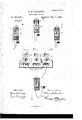
sulated, as shown, by hard-rubber bushing. The `lever D, (shown by Fig. 2 in detail,) in combination with spring I and frame or-back 35E, and pivoted to E, as shown at r, Fig. 3, ltakesthe place of the single piece N.
In the single piece N advantage is taken of the `elasticity of the metal. FrameE is provided with` two holes, x and y, and a slot, in which lever Theinner edge of the lever B pro- `jects so as to come within the edges of the plug-holes x and y, as shown by dotted line, and when a plug is inserted in either hole the lever isforced down, as shown by lower dot- .45 ted line, and the points of contact D C are separated, G taking the position shown as indicated by C.
a is a metallic plate screwed to hard-rubber block b, and thereby insulated from the other 5o portions ofthe switch.
. Be it known that I, CHARLES ScRIBNnn, of the city of Chicagol in the county of Cook and- State of Illinois, have invented certain new changeApparatus, of which the following is My invention `relates to the nieansof r 5 making these connections.
raient No. 293,198, dated February 5, lese.
nl es, issn, No. 50.413,
. l .In Fig. 4 is shown the cut-out connected with subscribers wire m and the relay and annunciator P and 0, and also `with the op- `which is provided with a metallic point, c, and conducting-cord d. The connections are formed as follows: The subscriber S, by throwl the wire on through the relay I), which, closing, the annunciator number of S is indicated at O, and thecurient passes along the wire H, and thence through the switch to 'the ground through wire G.
plug A as shown, an'dS is in communication with the operator atJ, o and a being in contact, as shown. This shorter circuit: being formed, the relay P and annunciator O4 are shunted, and the leverCB is forced down by the plug, and pointsof contact D Care sepa rated, as before described, and shown in Fig". 8,. and the ground-wire G thereby thrown off.'` Each subscriber has a separate switch, and wewill now let Fig. '3 represent the switch of arsubscriber with whom S wishes to comminnicate, and whom we will designate as sub scriber second, Si. S now informs the opera# tor that he wishes to communicate with S2.
municates the order of S to the switchman. The switclnnan being provided with a cord a 'plug similar to A, inserts one of the plugs in `0c of'Fig. et, and the other plug in 7/ of Fig. 3. Operator is now in connection with S and S2,
and they are connected with each other. The operator then throws his calling-battery upon nection is made, and at the same time calling up S2. He then listens to the flrstfew words to assure himself that the connection is comparties S and S2 are` now connected and the S2 are through talking, one or the other of them throws his local battery to line, which closes the relay W, thus tripping annunciatcrLneedie O and notifying switchman to disconnect their lines. This he does by removing the erators telephone J,'by means of the plug A,
similar to d, to either-end of which is attachedv plete, and then informs the switchman, who thereupon removes plugA from y, Fig. 4. The
shunt is removed fromrelay I. Vhen S and 9 Application filed August 13, lTQ. .Patented in England November 2S), 1379, No. 4,103; inrFrnr ce January 1F, ISEO, No 134,596, and
ing on his local battery, sends a current along ,i r
The switchman, being thus Y, notiiedby the annunciator, at once inserts' Operator, by a speaking-tube or otherwise, com` both lines, thereby informing S that the con- IOO outfit at station of S2 to ground.
Aof three subscribers, S S S2, connected by telephone-lines m m fm, respectively, with my spring-j ack switches at the central office. switches of S and S are shown connected together by the llexible cord d. The operators telephone J is shown includedin a branch circuit to ground. By means of the usual pushbutton c, the battery may be thrown upon both lines m and m2. The operator listens until he .finds that S and S2 have commenced talking, and then removes the plug of cord d from the switch ofthe line of S. The circuit between the stations of S and Si' may be traced as follows after the operator has disconnected his outfit: from ground at station of S, through the call box, and by line m through the relay I,wh'ich now serves as a clearingout annunciator, thence to the frame of the spring-j ack switch of line lmy, and .from said switch, by cord d, to line F2, and thence to line m2, and through the vVhen theJ subscribers signal that t-hey are through talking, the operator v'removes the terminal plugs of cord d from their switches, and their lines are at once, by the action of the switches, closed to ground. In case the subscribers forget to send in the clearing-out signal, the operator connects his telephone in derived circuit to the lines and listens out. The station of S is shown connected with the central otiice by line m through the switch and annunciator to ground.
I claiml. In a telephoneexchange, two subscribers telephone-lines, each line permanently con nected with the metallic frame of its switch at the exchange-station, the switch of each line being provided with an insulated ground-contact point, a contact-piece which closes on said contact-point, and a plug-hole in the frame adapted to direct a plug against said contact-piecein combination with a iiexible conduetingcord provided with terminal plugs, whereby the two telephone-lines may be connected together while the contact-pieces are at the same time disconnected from the ground- Contact points.
2. The combination, ina telephone-exclilange switch, of a metallic frammprovided with a The plughole and linsulated ground-contact point a telephone line permanently in electrical connection with. the movablecontact piece or` lever of the switch, and a metallic pointedy plug adapted to be inserted in said plug-hole, whereby the switch lever is disconnected from the contact-point and connected tothe plug-point, asl and for the purpose specified.
3. The switch, in combination with the plug and4 circuits whereby the relay is shunted at the same time the ground-wire is taken off.
et. A switch provided with two plug-holes and contactpoints C D, in combination with a plug and means whereby the contact of said points is broken when a plug is inserted in either hole, said points closing when said plug is removed-that is, when there is no plug remaining in either hole.
5. A switch consisting of frame E, lever B,
and springy I, combined, substantially as set forth.
6. A switch consisting of frame E, lever B,
` spring I, block of 'hard rubber I), and platea,
combined substantiallyl as and for thepurpose specified.
7. In a telephone-switch, plate a and frame E, insulated by a block of insulating material,and combined substantially as shown and set forth. i i
S. In a telephone switch, the combination of plate a and insulated frame E,with lever B,
contactpoints C D. and a conducting plug, whereby the circuit is broken at point D, while at the Sametime the frame E and plate l a are connected.
9. The combination, with the telephonelines connected together for conversation, ot' a'branch circuit to ground-at the central of- 'liee, including a telephone and a switch and plug provided with a iieXible conducting-cord, as described, whereby said branch circuit may be connected with and disconnected from the circuit of said united telephone-lines.
10. In a spring-jack switch, the combination, with a normally-insulated metallic piece, ot' a movable contact piece or lever, a contact-point, and a connectingplug adapted to l separate the said movable contact piece or lever fromsaid contact-point, and at the same time to form an electric connection between said movable contact piece or lever and said normally-insulated metallic piece.
CHARLES E. SCRIBNER. iVitnesses:
GEORGE P. BARTON, NVALLACE L. DnNVoLF.
Publications (1)
| Publication Number | Publication Date |
|---|---|
| US293198A true US293198A (en) | 1884-02-05 |
Family
ID=2362385
Family Applications (1)
| Application Number | Title | Priority Date | Filing Date |
|---|---|---|---|
| US293198D Expired - Lifetime US293198A (en) | Ments |
Country Status (1)
| Country | Link |
|---|---|
| US (1) | US293198A (en) |
-
0
- US US293198D patent/US293198A/en not_active Expired - Lifetime
Similar Documents
| Publication | Publication Date | Title |
|---|---|---|
| US293198A (en) | Ments | |
| US592359A (en) | Milo g | |
| US592301A (en) | Milo g | |
| US680879A (en) | Telephone-exchange apparatus. | |
| US592339A (en) | Milo g- | |
| US592391A (en) | Milo g | |
| US730291A (en) | Telephone-exchange system. | |
| US554399A (en) | Charles e | |
| US386886A (en) | Multiple switch-board | |
| US592357A (en) | Milo g | |
| US759762A (en) | Signaling apparatus for telephone-switchboards. | |
| US592369A (en) | mllo g | |
| US592361A (en) | Milo g | |
| US592303A (en) | Milo g | |
| US592338A (en) | Milo g | |
| US387888A (en) | Multiple switch-board | |
| US386887A (en) | Multiple switch-board | |
| US387645A (en) | Multiple switch-board | |
| US590136A (en) | Of same place | |
| US385863A (en) | Multiple switch-board | |
| US383013A (en) | scribner | |
| US330065A (en) | scribner | |
| US557154A (en) | Charles e | |
| US592346A (en) | Milo g | |
| US592372A (en) | Milo g |