US291663A - William h - Google Patents
William h Download PDFInfo
- Publication number
- US291663A US291663A US291663DA US291663A US 291663 A US291663 A US 291663A US 291663D A US291663D A US 291663DA US 291663 A US291663 A US 291663A
- Authority
- US
- United States
- Prior art keywords
- key
- barrel
- projection
- lock
- spindle
- Prior art date
- Legal status (The legal status is an assumption and is not a legal conclusion. Google has not performed a legal analysis and makes no representation as to the accuracy of the status listed.)
- Expired - Lifetime
Links
- 239000002184 metal Substances 0.000 description 2
- 238000010276 construction Methods 0.000 description 1
- 238000006073 displacement reaction Methods 0.000 description 1
- 230000037431 insertion Effects 0.000 description 1
- 238000003780 insertion Methods 0.000 description 1
Images
Classifications
-
- E—FIXED CONSTRUCTIONS
- E05—LOCKS; KEYS; WINDOW OR DOOR FITTINGS; SAFES
- E05B—LOCKS; ACCESSORIES THEREFOR; HANDCUFFS
- E05B15/00—Other details of locks; Parts for engagement by bolts of fastening devices
- E05B15/08—Key guides; Key pins ; Keyholes; Keyhole finders
-
- Y—GENERAL TAGGING OF NEW TECHNOLOGICAL DEVELOPMENTS; GENERAL TAGGING OF CROSS-SECTIONAL TECHNOLOGIES SPANNING OVER SEVERAL SECTIONS OF THE IPC; TECHNICAL SUBJECTS COVERED BY FORMER USPC CROSS-REFERENCE ART COLLECTIONS [XRACs] AND DIGESTS
- Y10—TECHNICAL SUBJECTS COVERED BY FORMER USPC
- Y10T—TECHNICAL SUBJECTS COVERED BY FORMER US CLASSIFICATION
- Y10T70/00—Locks
- Y10T70/70—Operating mechanism
- Y10T70/7441—Key
- Y10T70/778—Operating elements
- Y10T70/7791—Keys
- Y10T70/7842—Single shank or stem
- Y10T70/7859—Flat rigid
-
- Y—GENERAL TAGGING OF NEW TECHNOLOGICAL DEVELOPMENTS; GENERAL TAGGING OF CROSS-SECTIONAL TECHNOLOGIES SPANNING OVER SEVERAL SECTIONS OF THE IPC; TECHNICAL SUBJECTS COVERED BY FORMER USPC CROSS-REFERENCE ART COLLECTIONS [XRACs] AND DIGESTS
- Y10—TECHNICAL SUBJECTS COVERED BY FORMER USPC
- Y10T—TECHNICAL SUBJECTS COVERED BY FORMER US CLASSIFICATION
- Y10T70/00—Locks
- Y10T70/80—Parts, attachments, accessories and adjuncts
- Y10T70/8432—For key-operated mechanism
- Y10T70/8595—Key guides, internal
Definitions
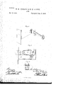
- Figure I a perspective view; ⁇ Fig. 2, a side view, one of the plates of the lock removed;
- This invention relates to an improvement in locks such as commonly used for doors, and
- the 2 5 invention consists in the constructionas herei inafter described, and more particularly re cited in the claim.
- A is the lock-case; B, the bolt; C, the tumbler, hung to the bolt, as at a, and so as to work over the stump b inthe usual manner.- too well known to require description in this specication.
- D is the barrel, having a circular projection, d, at each end, which works in a correp spending shaped seat in the two plates of the lock-case.
- the barrel is substantially square, as seen in Fig. 2, or at least with three sides.
- Through one side of the barrel is a longitudinal slot, e, corresponding to the key-hole f in ⁇ 4o the lock-plates, the width of the slot .corresponding to the thickness of the key, the key being made from sheet metal, as seen in Fig. l.
- a projection, h. is made close up to the bearing of the barrels, and which projection extends, say, halfway (more or less) across Athe key-hole, so that at the periphery of the bearing the key-hole in the lock-plates is somewhat narrower than the bit of the key, and in 5o the bit, close to the spindle, a longitudinal ticularly to that class in which the key is made groove, '5, is cut corresponding to the projection h, and so that when the key is inserted into the keyhole on one side the groove will follow the projection h on that side and serve as a guide for the key to conduct the spindle to its bearing in the opposite plate above the projection on that side.
- the projection h in the one plate is on the opposite side to the projection on the other plate, "and so that the key may be inserted 6o from either side.
- These two projections hthe one in the one plate and the other in the opposite plate-serve as a bearing on which the spindle will rest, and without which, it will be observed, if the key were introduced into the key-hole and barrel, it would fall fall downward out of place and have no support to retain it in its proper relative position to the barrel until it could be turned with the barrel to bring the key within the control of 7o the bearings of the barrel.
- the key After the key has been thus inserted, it is turned in the usual manner, and with it the barrel is turned until the bit of the key will operate to raise the tumblers and throw the bolt in the usual manner.
- the upper side of the barrel is ⁇ made flat, so that the tumbler will rest thereon under the force of the spring, and thus will serve to keep the barrel in it's proper relation to the keyhole i'or'the insertion of the key.
- the tumbler catches the opposite flat side of the barrel before the bit of the key has come into line with the keyhole, and there arrests the barrel, and so asto hold the key in that position as it did in the opposite direction, and thereby prevent accidental dis ⁇ placement of the key when the bolt is drawn.
- the opposite at sides of the barrel serve as a cheek to the turning of the key7 so as to indieate to the person operating ⁇ the key that further turning is 'unnecessary unless lie desires to remove the key.
Description
(No Model.) W. ANDREWS 8a H. H. SPARKS.
8 1.00K. No, 291,668. Patented Ja.`11.8, 1884.
fj] UNITED STATES PATENT OFFICE.
W'ILLIAM H. ANDREVS AND HENRY H. SPARKS, OF NEV HAVEN, CONN., ASSIGNORS TO MALLORY, VHEELER St OO., OF SAME IJLAGE.
Look.
SPECIFICATION forming part of Letters Patent No. 291,663, dated January 8, 1884.
Application filed June'll1 1883. (Nomodel'.) i i i "1o exact description of the same, and which said drawings constitute part of this specification,
and represent, in-
Figure I, a perspective view;` Fig. 2, a side view, one of the plates of the lock removed;
i Fig. 3, a vertical central section through the keyhole.
This invention relates to an improvement in locks such as commonly used for doors, and
may be either rnortise77 or ri1n,77 and parfrom ilat sheet metal, and in which a rotating barrel is arranged in the lock-case to receive the spindle portion of the key and serve as a bearing upon which to turn the key; and the 2 5 invention consists in the constructionas herei inafter described, and more particularly re cited in the claim.
A is the lock-case; B, the bolt; C, the tumbler, hung to the bolt, as at a, and so as to work over the stump b inthe usual manner.- too well known to require description in this specication.
D is the barrel, having a circular projection, d, at each end, which works in a correp spending shaped seat in the two plates of the lock-case. The barrel is substantially square, as seen in Fig. 2, or at least with three sides. Through one side of the barrel is a longitudinal slot, e, corresponding to the key-hole f in `4o the lock-plates, the width of the slot .corresponding to the thickness of the key, the key being made from sheet metal, as seen in Fig. l. At one side of the key-hole in each ofthe plates a projection, h., is made close up to the bearing of the barrels, and which projection extends, say, halfway (more or less) across Athe key-hole, so that at the periphery of the bearing the key-hole in the lock-plates is somewhat narrower than the bit of the key, and in 5o the bit, close to the spindle, a longitudinal ticularly to that class in which the key is made groove, '5, is cut corresponding to the projection h, and so that when the key is inserted into the keyhole on one side the groove will follow the projection h on that side and serve as a guide for the key to conduct the spindle to its bearing in the opposite plate above the projection on that side. It will be understood that the projection h in the one plate is on the opposite side to the projection on the other plate, "and so that the key may be inserted 6o from either side. These two projections hthe one in the one plate and the other in the opposite plate-serve as a bearing on which the spindle will rest, and without which, it will be observed, if the key were introduced into the key-hole and barrel, it would fall fall downward out of place and have no support to retain it in its proper relative position to the barrel until it could be turned with the barrel to bring the key within the control of 7o the bearings of the barrel. After the key has been thus inserted, it is turned in the usual manner, and with it the barrel is turned until the bit of the key will operate to raise the tumblers and throw the bolt in the usual manner. The upper side of the barrel is `made flat, so that the tumbler will rest thereon under the force of the spring, and thus will serve to keep the barrel in it's proper relation to the keyhole i'or'the insertion of the key. 8o When the key has been inserted and turned, say, tothe locked position, as seen in Fig, 2, the second flat side of the barrel will receive the pressure of the tumbler-spring, the tuinbler bearing on that side of the barrel, solas to hold the barrel and key in that position, from which it cannot be turned without rst overcoming the power of the tumbler-spring, and this cannot accidentally occur; hence when the bolt is thrown and the keyleft in the lock it is held lthere against any accidental displacement 5 or when the key be turned to the unlocked position, as also seen in broken lines, Fig. 2, the tumbler catches the opposite flat side of the barrel before the bit of the key has come into line with the keyhole, and there arrests the barrel, and so asto hold the key in that position as it did in the opposite direction, and thereby prevent accidental dis` placement of the key when the bolt is drawn. IOC
The opposite at sides of the barrel serve as a cheek to the turning of the key7 so as to indieate to the person operating` the key that further turning is 'unnecessary unless lie desires to remove the key.
From the foregoing it will be understood that We do not claim, broadly, a rotating barrel arranged in the look to receive the spindle portion of the key, and which barrel will turn with the key; neither do We olaim,broad 1y, a support which will hold the spindle of the key in the barrel and parallel therewith, as such, We are aware, is not new 5 ybut in previous constructions the support for the key y has been in the barrel itself and independent of the case or plates of the look-that is, by a groove through the barrel parallel with its axis, and the key constructed with a correnal groove, i, at its junotion with the spindle, 3
substantially as and forthepurpose described.
VILLIAM H. ANDREVS.
. HENRY H. SPARKS.
Vitnesses:
JOHN E. EARLE, Jos. GQEARLE..
Publications (1)
| Publication Number | Publication Date |
|---|---|
| US291663A true US291663A (en) | 1884-01-08 |
Family
ID=2360851
Family Applications (1)
| Application Number | Title | Priority Date | Filing Date |
|---|---|---|---|
| US291663D Expired - Lifetime US291663A (en) | William h |
Country Status (1)
| Country | Link |
|---|---|
| US (1) | US291663A (en) |
Cited By (1)
| Publication number | Priority date | Publication date | Assignee | Title |
|---|---|---|---|---|
| US20050269327A1 (en) * | 2004-05-21 | 2005-12-08 | Chafe Adam J | Container |
-
0
- US US291663D patent/US291663A/en not_active Expired - Lifetime
Cited By (1)
| Publication number | Priority date | Publication date | Assignee | Title |
|---|---|---|---|---|
| US20050269327A1 (en) * | 2004-05-21 | 2005-12-08 | Chafe Adam J | Container |
Similar Documents
| Publication | Publication Date | Title |
|---|---|---|
| US291663A (en) | William h | |
| US564029A (en) | sargent | |
| US599765A (en) | Permutation-lock | |
| US550111A (en) | sargent | |
| US1022268A (en) | Combination-lock. | |
| US1246472A (en) | Padlock. | |
| US582367A (en) | Edward j | |
| US1232035A (en) | Lock construction. | |
| US276516A (en) | Lock for drawers | |
| US660230A (en) | Lock. | |
| US103838A (en) | Improvement in locks | |
| US443261A (en) | sargent | |
| US121142A (en) | Improvement in door-locks | |
| US203783A (en) | Improvement in log kino-latches | |
| US200511A (en) | Improvement in cylinder-locks | |
| US180875A (en) | Improvement in padlocks | |
| US1120816A (en) | Keyhole-lock. | |
| US189294A (en) | Improvement in master-key locks | |
| US76066A (en) | Improvement in dooe-looks | |
| US716671A (en) | Combined lock and latch. | |
| US120704A (en) | Improvement in door-locks | |
| US805042A (en) | Sliding-door lock. | |
| US640956A (en) | Lock. | |
| USRE11465E (en) | James roche | |
| US212908A (en) | Improvement in locks |