US2908758A - Toll ticketing telephone systems - Google Patents
Toll ticketing telephone systems Download PDFInfo
- Publication number
- US2908758A US2908758A US308957A US30895752A US2908758A US 2908758 A US2908758 A US 2908758A US 308957 A US308957 A US 308957A US 30895752 A US30895752 A US 30895752A US 2908758 A US2908758 A US 2908758A
- Authority
- US
- United States
- Prior art keywords
- line
- station
- subscriber
- relay
- exchange
- Prior art date
- Legal status (The legal status is an assumption and is not a legal conclusion. Google has not performed a legal analysis and makes no representation as to the accuracy of the status listed.)
- Expired - Lifetime
Links
Images


Classifications
-
- H—ELECTRICITY
- H04—ELECTRIC COMMUNICATION TECHNIQUE
- H04M—TELEPHONIC COMMUNICATION
- H04M15/00—Arrangements for metering, time-control or time indication ; Metering, charging or billing arrangements for voice wireline or wireless communications, e.g. VoIP
- H04M15/38—Charging, billing or metering by apparatus other than mechanical step-by-step counter type
Definitions
- the present invention relates to automatic telephone systems in general and in particular to improvements in automatic telephone ticketing systems arranged to produce records of certain items of information pertaining to each telephone connection so that an appropriate charge may be assessed for each connection.
- toll ticketing telephone connections are completed under control of a register sender or director provided in the originating telephone exchange.
- a detector is controlled to determine the directory number of the calling station and it registers the detected calling number in the register sender.
- the register sender transfers the items of record information registered therein, including the calling station directory number, the called station directory number, the rate of charge for the call, and other pertinent items of record in- ⁇ formation, to a toll ticket repeater in the originating exchange that has been selected during the course of setting up the connection.
- the toll ticket repeater stores the items of information transferred thereto and it also accumulates and registers the total elapsed conversation time of the connection.
- a recorder controller for example, a printer controller or a tabulator, is associated with the toll ticket repeater and the items of record information stored therein are then transferred to the record controller.
- the toll ticket repeater Incident to the completion of the transfer of the items of information, the toll ticket repeater is restored to normal and rendered available for use in other toll ticketing calls. Thereafter, the recorder controller controls recording apparatus to produce an individual record and a common record of the items of information pertaining to the completed connection.
- Automatic toll ticketing apparatus of the type descr'bed above is usually employed in a relatively large metropolitan area which is' normally divided into a plurality of zones and each zone includes one or more 10,000 line telephone exchanges. Also, each of the exchanges in the network is provided with all of the toll ticketing apparatus necessary for recording the toll calls originated in the associated exchange. Since the apparatus provided in each exchange of a toll ticketing system is quite complicated to manufacture and install, such apparatus can not economically be used in telephone networks served by small exchanges having, for example, 5,000 or less subscriber lines.
- Figs. 1 to 13, inclusive taken together, illustrate the details of the apparatus incorporated in the central exchange B and a remote exchange C of the toll ticketing telephone system, which apparatus has incorporated therein the features of the invention as briefly outlined above;
- Fig. 14 illustrates the mode of combining Figs. l to 13, inclusive, to form a unified system;
- Fig. 15 schematically illustrates a trunking layout of apparatus provided in the central exchange B and the remote exchange C of a telephone system embodying the present invention;
- Fig. 1 to 13, inclusive taken together, illustrate the details of the apparatus incorporated in the central exchange B and a remote exchange C of the toll ticketing telephone system, which apparatus has incorporated therein the features of the invention as briefly outlined above;
- Fig. 14 illustrates the mode of combining Figs. l to 13, inclusive, to form a unified system;
- Fig. 15 schematically illustrates a trunking layout of apparatus provided in the central exchange B and the remote exchange C of a telephone system embodying the present invention
- FIG. 16 schematically illustrates the manner in which the dial or calling device at each of the different stations on a party line in exchange C transmits switch controlling loop impulses corresponding to digits of a called station number and station identifying ground impulses identifying a particular calling station on a party line; and Fig. 17 schematically illustrates the manner in which the dial or calling device at each of the different stations on a party line in exchange B transmits switch controlling loop impulses corresponding to the digits of a called station number and station identifying ground impulses identifying a particular calling station on the party line.
- Figs. 1 to 7, inclusive illustrate the details of one of a plurality of ticketers 700 provided in the central exchange B and which is utilized in toll connections established between subscriber stations in exch-anges B and C.
- the ticketer 700 includes a code storage register 302 for registering the four digits identifying the numerical portion of the directory number of a calling station in exchange B as detected by the detector 1900.
- the schematically illustrated detector 1900 is arranged to identify the calling station number and toregi'ster the digits identifying the calling station in the ticketer 700.
- the detector 1900 may be substantially identical to the detector 1900 illustrated in the Ostline Patent No. 2,639,330, issued May 19, 1953.
- the ticketer 700 includes a digit register 509 which includes the individual registers S10, 520 and 530 for registering the three digits identifying a calling station in the remote exchange C and it includes the individual digit registers 540 to 580, inclusive, for registering the digits identifying a called station in exchange C if the call is an outgoing call from exchange B or for registering the digits identifying a called station in exchange B if the call is incoming to the exchange B. Also, the ticketer 700 includes a storage transfer switch 701 for transferring various items of record information, las stored in the different registers of the ticketer, to a schematically illustrated tabulator 745..
- the tabulator 745 is arranged so that it will control the schematically illustrated ticket tape perforator 755 andthe record tape perforator 750 to perforate tapes in accordance with the various items of record information and in accordance with the date and time as registered in the schematically illustrated date and time unit 760.
- the tabulator allottr 744, the tabulator 745, the record tape perforator 750, the ticket tape perforator 75S and the date and time unit 760 may be substantially the same asthe corresponding units disclosed and described in detail in the Ostline Patent No. 2,678,353, issued on May ll, 1954.
- Fig. 8 and a portion of Fig. l schematically illustrate certain of the switching apparatus provided in the central exchange B for establishing local calls, incoming toll ticketing calls and outgoing toll ticketing calls.
- Figs. 9 to 12, inclusive illustrate the details of one of a plurality of ticket repeaters 900 provided in the remote exchange C.
- the ticketer 900 includes a tens digit register 1170, a units digit register 1180, and a station digit register 1190 for registering the number of the calling station in exchange C.
- Fig. 12 also illustrates the detai-ls of an allotter 1270 for connecting a common calling line verier 1301 to anyy one of the plurality of the ticket repeaters 900 that is in use in a call from exchange C to exchange B.
- Fig. 13A illustrates the details of the calling line verifier 1301 which is utilized in conjunctionwith a ticket repeater to ascertain whether or not a calling subscriber in exchange C has accurately dialed his own telephone number in the course of setting up a toll ticketing call to a subscriber in exchange B.
- Fig. 13 also schematically illustrates the switching apparatus in exchange C for establishing local calls, incoming toll ticketing calls and outgoing toll ticketing calls.
- a subscriber in exchange B desires to establish a toll ticketing call withl a subscriber in a remote exchange C
- the linecircuit 120, distributor 123 and finder 1,21 will operate in a conventional manner to connect the calling subscriber line to an idle rst selector, such as the first selector 122.
- the line circuit 120 ' is individual to a live-party line including the stations having the directory numbers 4574 to 4974. It should be understood, however, that similar line circuits may be utilized for each party line and for each individual line in the exchange.
- the line circuit 120 will cause the distributor 123 to select an idle finder, such as the nder 121 and the latter mechanism will operate in a vertical and rotary direction to lind the calling line.
- the selector 122 individually associated with the nder 121 will transmit the usual dial tone signal to the calling subscriber. Thereafter, a subscriber may dial the digits 90-6-521.
- the digit 9 as dialed by the calling subscriber will control the rst selector 122 to raise its wipers to the ninth level and then to rotate its wipers over the bank contacts in the ninth level to select an idle ticketer, such as the ticketer 700.
- the next digit dialed by the calling subscriber will be registered in the ticketer 700 to indicate that the call is to be a toll ticketed call.
- the special dial in the calling station on the party line will transmit one or more ground impulses in the manner to be explained hereinafter to register in the ticketer 700 the number of the particular calling station on the calling party line.
- the ticketer 700 will cause the detector 1900 to associate itself with the ticketer 700 and to automatically detect the number of the calling station on the party line. In the present call, the detector 1900 will detect the digits 4574 of the directory number of the calling station and it will register these digits in the ticketer 700.
- the next digit 6, dialed by the calling subscriber 6 is repeated by the ticketer 700 to the associated trunk selector 801.
- This selector in response to the digit 6 will raise its wipers to the sixth level and it will then rotate its wipers over the selected level to search for an idle trunk circuit, such as the trunk circuit 810 terminating a toll line extending to the remote exchange C.
- the ticket repeater 900 in exchange C is selected and a circuit is completed for controlling the incoming connector 1320,
- the calling subscriber now dials the digit 5 which is repeated by the ticketer 700 over the above connection including the trunk circuit 810, the toll line TL811 and the repeater 900v to the incoming connector 1320.
- This connector now raises its wipers to the fifth level.
- the subscriber then dials the digit 2 and causes the incoming connector 1320 to rotate its wipers two steps into engagement with the second set of contacts in the fth level.
- the last digit is now dialed by the calling subscriber and it controls the incoming connector 1320 to transmit a particular frequency of ringing current over the selected line to ring the called subscriber at station 521.
- the connector is a three-digit frequency ringing connector.
- it may also be of the code ringing type in which case the ringing current will be transmitted to the called line in accordance with a particular code, in a conventional manner.
- other subscriber lines in the remote exchange C may be of the party type and, consequently, the last digit of the directory number of a called party on a party line may be, for example, any one of the digits 2, 3, 4 or 5 if the lines areV of the four-party type.
- the ticketer 700 in the central exchange B will start timing the call and when the connection is terminated, the ticketer 700 will have registered therein the total elapsed time of the conversation. Thereafter, the ticketer 700 will, cause the tabulator allotter 744 to associate the tabulator 745 with the ticketer 700 and all of the items of information stored in the ticketer 700 will be transferred to the tabulator 745. The latter mechanism in turn will then control the ticket tape perforator 750 and the record.
- tape perforator 755 to record, for example, a three digit number identifying the particular ticketer 700 utilized inthe connection; a three digit number indicating the number of minutes that the connection is established between the calling and called subscribers; the three digits 521 identifying the directory number of the called station in the remote exchange C; the digit 6 identifying the called remote exchange C; the four digits 4574 identifying the directory number of the calling station in the central exchange B; and also the digit 4 identifying the callingl central exchange C.
- The, above items of record information are transferred from the ticketer 700 to the tabulator 745 in the order named andthe tabulator 745 controls the ticket tape and record tape mechanisms 750 and 755 in substantially the same manner but also includes additionall items of information pertaining to the date and the, time that the tabulator recorded the information.
- the toll ticketed call is originated by a subscriber in thecentral exchange B and is extended to asubscriber in the remote exchange C. If a1 subscriber, in the remote exchange C originates a call,
- the line circuit 41316 will control the distributor 1317 to select an idle nder 1318 and the finder in turn will find the calling subscriber line in a conventional manner.
- the calling subscriber at station 521 is noW connected to the local connector 1319 which transmits the usual dial tone signal to the calling station.
- the apparatus, as illustrated, in the .exchange 'C is commonly referred to as a finder-connector sys- -tem in that it does not have suiiicient subscriber lines itc-require the use of first or second selectors.
- the exchange C is a 100 line exchange serving 100 subscriber lines.
- the subscriber at station 521 may now dial the digits 90-521-4-4574 to extend a toll ticketing call to a subscriber in exchange B.
- the rst digit 9 will control the local connector 1319 to raise its wipers to the ninth level and to automatically rotate it wiper over the selected ninth level to search ⁇ for 'an idle ticket repeater, such as the ticket repeater 900.
- the local connector 1319 is of the trunk hunting type, at least on the ninth level thereof and will automatically select and seize an idle ticket repeater.
- the next digit dialed Iby the subscriber at station 521 is the digit which is registered in the 0 register 915 in the ticket repeater 900.
- the registration of ⁇ this digit causes the ticket repeater 900 to extend a connection by ⁇ way of the toll line TL811 to the trunk circuit 810.
- the trunk circuit 810 causes the allotter 815 and its :associated rotary switch 816 to select an idle ticketer, such as the ticketer 700 in exchange B. If the calling station is on a partyline, then during the dialing of the second digit 0, one or more station identifying ground pulses will be transmitted and registered in the ticket re- 4preater 900 to indicate Athe particular station on -a party ⁇ line that is making ythe call.
- the ticket re- 4preater 900 indicates Athe particular station on -a party ⁇ line that is making ythe call.
- the dial at this station is of conventional construction and does not transmit any station identifying ground pulses to the ticket repeater 900.
- the call originated on a party line one or more station identifying ground pulses will be transmitted by the calling station dial at the same time as the ten impulses of the digit 0 are transmitted to the ticket repeater 900.
- the calling subscriber Following the digit 0 the calling subscriber must now vdial his own station number, the digits 521, to the ticket repeater 900. These digits are registered in the digit registers 1170, 1180 and 1190 in the repeater and cause the allotter -1270 to associate the verifier 1301 with the ticket repeater 900.
- the impulses of the digits 521 dialed by the calling subscriber lare also repeated, by the ticket repeater 900, over the toll line TL811 and then by way of the trunk circuit 810 and the allotter 815 to the ticketer ,700 where they are also registered.
- the ticketer 700 in the central exchange B registers the digits of the calling subscriber number as ⁇ they are dialed.
- the vertifer 1301 will check the same and will permit lthe ticket repeater 900 to also repeat subsequent digits dialed by the calling subscriber over the toll line TL811 to the exchange B.
- the ticketer 700 In response to the first digit 4 identifying the called exchange B of the called number, the ticketer 700 also controls the trunk selector 801 to raise its Wipers to the fourth level and then rotate its Vwipers to select an idle incoming selector, such as the incoming selector 802.
- the next digit 4 of the called num- .ber will cause the ticketer 700 to control the incoming selector 802to Iraise its wipers to the fourth level and then y'rotate its wipers over the selected level Vto lselect an idle -second sleector, such as the second selector 803; which l 6 A has access to connector switches in the 500 group.
- the next digit 5 of the called number will cause the ticketer 700 to control the second selector 803 to raise its wipers to the fth level and then rotate its wipers over the selected fifth level to select an idle connector, suchras the connector 804.
- the last two digits 74 of the called subscriber directory number will also be repeatedV by the ticketer 700 to control the connector 804 in the 500 group to select the line of the called subscriber.
- This connector since it is in the 500 group, will transmit a particular frequency of ringing current which will ring the bell at only the subscriber station 4574 on the tive party line.
- Other connectors in the other hundred groups will transmit particular ringing frequencies to selectively signal only the subscriber stations having corresponding ringers at their stations.
- the ticketer 700 starts timing the connection after the called subscriber at station 4574 answers the call and upon the release of the connection the conversation timer will have stored therein the total elapsed conversation time of the telephone connection.
- Local calls may also be established between the subscribers in exchanges B or C without producing a record of such local calls.
- the party line subscriber at station 4574 in the central exchange B may establish a connection with another subscriber in 'the same exchange by dialing the four digits identifying the called subscriber station.
- the subscriber at station Vthe subscriber may dialthe first digit of the local called station into the iirst selector 122.
- the rst selector will raise its wiper to the selected level (except level 9 which is reserved for calls to exchange C) and then rotate its wipers over the selected level to Search foran idle second selector, such as the second selector 803.
- the second digit dialed by the calling subscriber will control the second selector 803 in a vertical and then a rotary direction in a conventional manner to select an idle connector, such as the connector 804.
- the iinal two digits dialed by the calling subscriber will have caused the connector to select the line to the desired called subscriber.
- the ringing current for signaling the called subscriber is automatically transmitted by the connector 804 in the usual manner and the conversational circuit will be completed when the called subscriber answers the call. All of the subscriber stations in Ithe central exchange B have four digit directory numbers and the value of the first digit will indicate the thousand group 4including the called subscriber station.
- the calling subscriber at station 521 in making a local call will remove his receiver and thereby cause the line circuit 1316, the distributor 1317 and the iinder 1318 to operate in a conventional manner to connect the calling line to the local connector 1319. Since the apparatus provided in exchange C is designed to handle calls for 100 subscriber lines, two digits would normally designate the line number of any desired called subscriber. However, inasmuch as some of 'the subscriber lines in this exchange are arranged for party line service, an additional digit is provided in the directory number of a called station to determine the ringing frequency to be utilized in signaling a particular station on a called party line.
- the calling subscriber station 521 desires to extend a connection to a called subscriber on a party line having the directory number 253.
- the digit 2 dialed into the local connector 1319 will raise the wipers to the second level and the second digit 5 will rotate the wipers over the contacts in the second level into engagement with the fifth set of contact banks.
- the last digit 3 of the called number will control the connector in a well known manner to transmit ringing current over the called line 25 to ring only the station on the party line having the directory number 253.
- the ringing signal will be terminated and the calling and called parties may converse.
- the central exchange B is arranged to serve 1,000 lines and the remote exchange C is arranged to serve 100 lines
- the apparatus in exchange B may also be arranged to handle telephone service for 10,000 subscriber lines if desired.
- the apparatus in exchange C may be arranged to serve 1,000 subscriber lines by introducing, for example, a first selector, such as the first selector 122, between the :finder 1318 and the local connector 1319.
- first and second selectors such as the first and second selectors 122 and 803, respectively, may be introduced between the iinder 1318 and the local connector 1319 in the same manner illustrated in the central exchange B.
- each of the subscriber station telephone instruments includes the usual handset having a transmitter and a Y receiver, a ringer and a calling device or dial.
- the calling device provided at each of the individual subscriber line stations is of conventional construction and arrangement, whereas, the calling device provided at each party subscriber station on a party line is of the construction and arrangement of that disclosed in the lohn E. Ostline Patent No. 2,410,520, granted November 5, 1946.
- the calling devices disclosed as stations 1 to 5, inclusive, (Fig. l) in the central exchange B are provided respectively with impulsing springs 111C to 115e, inclusive, and they are respectively provided with cam springs 111a to 11511, inclusive, and associated cams 111b -to 115b, inclusive.
- the set of impulsing springs are operated in accordance with the return movement of the associated finger wheel (not shown) to transmit a variable number of series of switch controlling loop impulses in accordance with the finger hole selected on the pull of the nger wheel.
- the cam springs are operated by the associated cam, during the return movement of the nger wheel in order to transmit a fixed number of station identifying ground impulses.
- Fig. 17 it will be seen that the impulsing springs at the various subscriber stations are arranged to interrupt a circuit including the line conductors C116 and C117 as is graphically represented by the line 1700 and that the station identifying Icams at stations 1 to 5, inclusive, on the five party line are arranged to apply ground potential to the line conductors as is graphically represented by the lines 1701 to 1705, inclusive.
- the line 1706 in Fig. 17 indicates that the individual line subscriber stations are not provided with station identifying cams and, consequently, do not transmit station identifying ground impulses.
- the line 1700 shows that ⁇ the dial impulsing springs at any calling station, during the return movement thereof, transmits kswitch controlling loop impulses over the conductors of the calling subscriber line in accordance with the value of the digit dialed.
- the lline 1701 represents the action of the cam 11-1b (Fig. 1) during the return movement of the dial at the station 1 on a party line to transmit a single short ground impulse just prior to the transmission of the last switch controlling loop impulses by the irnpulsing springs 111c.
- the line 1702 represents the action of the cam 1-12b lto transmit a first short ground ⁇ impulse just prior to the transmission of the next to the last switch controlling loop impulse and to transmit a second short ground impulse between the transmission of the next to the last and the last switch controlling loop impulse by the impulsing springs 112C at the station 2 on the party line.
- the line 1703 represents the action of the cam 113b to transmit three short ground impulses during the return movement of the dial at station 3 on ythe party line.
- the'rst short ground impulse is transmitted just prior to the transmission of -the next to the last switch controlling loop impulse
- the second short ground impulse is transmitted between the transmission of the next to the last and the last switch controlling loop impulse
- the third ground impulse is transmitted immediately after the transmission of the last switch controlling loop impulse by the impulsing springs 113e.
- the line 1704 represents the action of the cam 114b, during the return movement of the dial at the station 4 on the party line to transmit one short ground impulse between the transmission of the next to the last and the last switch controlling loop impulse and to then transmit a short ground impulse following the transmission of the last switch controlling loop impulse by the impulse springs 114C.
- the line 1705 represents the action of the cam 11Sb, dur-ing the return movement of the dial at the station 5 on the party line to transmit a single short ground impulse following the transmission of the last switch controlling loop impulse by the impulsing springs 115C.
- Fig. 16 it will be seen lthat the irnpulsing springs at the various subscriber stations in exchange C are arranged to interrupt the circuit including the line conductors C1309 and C1310 (Fig. 13) as is graphically represented by the line 1600. It Will also be seen that the station identifying cams at the stations 2 to 5, inclusive, on a four party line are arranged to apply ground potential to the conductors as is graphically represented by the lines 1602 to 1605, inclusive.
- the line 1601 indicates that the individual subscriber stations and, if necessary, the station 1 on a ve party line are not provided with cams and, consequently, do not transmit station identifying ground impulses.
- the manner in which the various cams 131219 to f1315b transmit station identifying ground impulses during the return movement of the associated dial is graphically represented in lines 1602 to 1605, inclusive, and is substantially the same as has been described above in connection with Fig. 17.
- the distributor 123 selects the line iinder 121 and that the latter iinder operates its wiper in a vertical and then a rotary direction in the well known manner to select the terminals in the associated bank terminating the calling line.
- the line finder 121 it extends the calling line to the individually associated first selector 122 and the latter selector transmits the usual dial tone signal to the calling subscriber to indicate that the dialing may be started.
- the above noted switching apparatus, including the line circuit 120, the distributor 123, the line nder 121 and the first selector 122 may be of conven-tional construction and arrangement and may be, for example, of the type illustrated in the Bakker Patent No. 2,289,896, granted July 14, 1942, and in the Saunders Patent No. 1,849,694, granted March l5, 1932.
- the first selector 122 now extends the connection from the ycalling subscriber line by Way of the cable C123 to the ticketer 700 illustrated in Figs. 1 to 7, inclusive.
- the cable C123 includes the conductor C414, the conductor C415 and the control conductor C416. If the ticketer 700 is busy, the control conductor C416 will be grounded in order to indicate the busy condition to the irst selector 122. Thus, as the selector rotates its wipers over the ninth level it will pass over contacts ter- ',minating ticketers having grounded control conductor corresponding to the C conductor C416.
- the lirst selector 122 seizes the ticketer 700 it extends the loop circuit, including the and conductors C116 and C117 of the calling line to the and conductors C414A and C415 (Fig. 4) of the ticketer 700. Also, the rst selector 122, upon seizing the ticketer 700, applies ground potential to the control conductor C416 (Fig. 2). that the ground potential applied to the conductor C416 is extended by way of contacts 262 and the winding of the seize relay R650, to battery. The seize relay R650 operates over this circuit and, at its contacts 655, it completes a circuit including the contacts 647 for operating 4the line cut-inrelay R450.
- the relay R450 operates it completes, at its contacts 451, 453 and 455, a circuit for further extending the and -lconductors C414 and C415 to the windings of the local line relay R430 and the polarized party line relay R420.
- the last mentioned circuit may be traced from the conductor C414, contacts 451, upper left-hand Winding of the repeating coil 490, contacts 453, winding of the local line Vrelay R430, resistor 435', negative terminal of the 50 volt auxiliary battery 436, positive terminal of the battery 436, resistance lamp L437, winding of the polarized party line relay R420, contacts 455, lower left-hand winding of the repeating coil 490, and the conductor ⁇ C415.
- the calling subscriber loop circuit including the line conductors C116 and C117, is now connected fby way of the line circuit 1,20, the line iinder 121, and
- the first selector 122 tothe windings of the relays R420- and R430 in the ticketer 700. Since the party line relay R420 isV of the polarized type, the current ow through its windings is in such a direction that the relay does not operate. However, the local line relay R430 operates at this time.
- the relay R610 connects a marking ground potential to certain of the bank contacts associated with the Wipers of the storage transfer switch 701. 4
- the release relay R460 As soon as the release relay R460 operates, at its contacts 466, it applies ground potential to the locking conductor C486. Finally, at the contacts 465, the relay R460 completes a circuit for energizing the lower polarizing winding of the answer relay R270. However, this relay will not operate until the' current flow through the upper winding of the relay is in the proper direction.
- the local line relay R430 in the ticketer 700 is now connected to the calling subscriber line and the ticketer 700 is in condition to respond to the impulses of the remaining digits dialed by the calling subscriber.
- the ground potential is returned over the C conductor C416 to now hold the selector 122, the line finder 121, and the line circuit in their operated positions under control of the ticketer 700. Also, this ground potential marks the calling line busy to all of the connectors in the exchange B having access to the calling subscriber line.
- the local line relay R430 In response to the dialing of the second digit, which in this case is the -digit 0, the local line relay R430 re- The first time the line relay R430 restores to normal it completes, at its contacts 433, a circuit including the contacts 457, 464, 458 and 474 for operating the pulse control relay R485 and the latter relay, at its contacts 487, further extends this operating ground potential by way of the contacts 641, 654, and 645 in order to operate the magnet'M663 of the 0 register 660.
- the magnet M663 is retained in its operated position until the line relay R430reoperates, at the end of the rst pulse, at which time the magnet restores to normal and advances its wipers 661 and 662 one step inv a clockwise direction.
- the above traced circuit for the magnet M663 is completed ten times.
- the wipers 661 and 662 of the register 660 are advanced into engagement with the contacts in the associated contact banks.
- the slow-to-release pulse control relay R485 is retained in its operated position.
- the local line relay R430 will be retained in its operated position during the interdigital pause between the transmission of the digit 0 and the following digit dialed by the calling subscriber.
- the pulse control relay R485 restores to normal and attempts to complete, at its contacts 486 and 488, two separate circuits.
- the irst circuit is provided to operate the relay R640 .if the digit 0 has been registered in the 0 register 660 and the second circuit is provided to operate the 0 failure relay R470 in the event that the digit 0 is not registered in the O register 660.
- the relay R640 interrupts a point in a circuit traced hereinafter, in order to prevent operation of the 0 failure relay R470.
- the relay R640 completes a circuit including the contacts 213, 154 and 147 for operating the detector start relay R220 in order to cause the detector 1900 to identify the directory number of the calling station and to register the digits thereof in the code storage register 302.
- the relay R640 interrupts the circuit for the line cut-in relay R450.
- the relay R450 now restores to normal in order to disconnect the loop circuit including the calling subscriber line from the party line relay R420 and the local line relay R430 and in order to connect the loop circuit to the windings of the line relay R440.
- the second circuit completed incident to the restoration of the pulse control relay R485 at the termination of the transmission of the digit 0 to the ticketer 700 includes the contacts 488, 644, 631 and the winding of the 0 failure relay R470, to battery.
- the contacts 631 are closed by operation of the control relay R630 and that the latter relay is operated as soon as the wiper 661 is advanced into engagement with the rst contact in the associated contact bank.
- Contacts l to 10, inclusive, of this bank are multiply connected to ground potential so that the relay R630 is retained operated during the time interval that the wiper 661 engages any one of the contacts l to 10, inclusive, in the associated contact bank.
- the 0 dialed digit relay R640 will not be operated incident to the restoration of relay R485 and, therefore, the above mentioned circuit will be completed for operating the 0 failure relay R470.
- the relay R470 Upon operating the relay R470 locks itself, at its contacts 475, to the grounded locking conductor C486. Also, at its contacts 474, the relay R470 interrupts a point in the circuit for the pulse control relay R485 in order to prevent reoperation of this relay if the subscriber should dial an additional digit.
- the relay R470 completes a circuit, whereby, a bus) tone source (not shown) connected to the conductor C477 transmits a busy tone signal over the conductor C414 tothe calling subscriber station and returned by way of the conductor C415, contacts 473 and the condenser 476 to ground. Accordingly, the calling subscriber receives a busy tone signal to indicate that the call cannot be completed to its destination.
- a bus tone source not shown
- the relay R470 interrupts a point in a loop circuit traced hereinafter extending to the trunk selector 801l
- the polarized party line relay R420 will not be operated during the transmission of the digit 0 to the ticketer 700. However, if the calling station is provided with a special dial of the type previously noted, then the party line relay R420 will operate and restore one or more times in accordance with the arrangement illustrated in Fig. 17 and will control the station identifying register 301 to indicate the particular station on the party line that is making the call.
- the special calling device when actuated in accordance with the digit 0, and, as a matter of fact, in accordance with any of the digits 2 to 9 ⁇ and 0, will transmit a corresponding number of regular loop impulses to control the line relay R430 and during the transmission of at least the last two impulses of the digit, the special dial will transmit 1, 2 or 3 short ground impulses to control the party line relay R420.
- the ground potential applied in this manner to the conductor C116 is extended over the previously traced circuits to the conductor C414 in the ticketer 700 and then to the winding of the local line relay R430. This ground potential retains the local line relay R430 in its operated position.
- the ground potential applied to the -iconductor C117 is extended over the previously traced circuit to the -iconductor C415 in the ticketer 700 and then to the winding of the polarized party line relay R420, the resistance lamp L437 and the terminal of the 50 volt exchange battery 435, to ground. At this time the current ow through the winding of the polarized relay is reversed from the direction of the current normally owing through the relay at the time the loop circuit is closed.
- the relay R420 momentarily operates in response to the first ground pulse.
- a momentary circuit is completed for operating the relay R310 in the station identifying register 301.
- the circuit for operating the relay R310 may be traced from ground at contacts 465 and then by way of the contacts 432, 421 and 312 and the winding of the relay R310, to battery.
- the relay R310 operates and at its X contacts 313 completes a locking
Description
Oct. 13, 1959 Filed Sept. ll. 1952 E. s. PETERSON TOLL TICKETING TELEPHONE SYSTEMS 14 Sheets-Sheet 1 T/CKETER 700 OC. 13, 1959 V5;, s, PETERSON 2,908,758
TOLL TICKETING TELEPHONE SYSTEMS Filed Sept. 1l, 1952 14 Sheets-Sheet 3 /CKETEH 700 'conf sro/m65 nfs/sm? 302 uom cam/v6 No.)
Fig. 3 INVENTOR.
Edward 5. Peerson BY I' Oct. 13, 1959 E. s. PETERsoN TOLL TICKETING TELEPHONE SYSTEMS Filed Sept. 11, 1952 RLSE 14 'Sheets-Sheet 4 645B la) C49 475 48e V :El I'b'FA/LURE Fig 4 n INVENTOI'?.
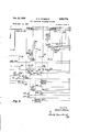
Edward S. Peerson.. BY M, @mW/Mz E; s. PETERsoN TOLL TICKETING TELEPHONE SYSTEMS Filed Sept. 11. 1952 14 Sheets-Sheet 5 DIGIT HE 6/.5` TER 509 RECE/vE SED.
uN/Ts DIC/T WXYZIZ TCKETER 02 A j D CALLED No. 58D C599 700 0% I1- l y o TENS DIC/r l \0 CALLED ND. 57D C579 ,5o g
HUNDREDS DIG/r "XYZ/4 1 CALLED No. 56D-l C569 u V- E,\=/ THDusANDs DIC/r "XYZ 5 50" CALLED No. 55D-I C559 CALLED DEFICE DIC/T WCX Y 916 REGISTER 54u uN/rs DIC/r WXYZ 20 CALL/NC ND. REC. 530 C539 rENs D/C/T il wxyze/ CALL/NC ND. REC. C529 1 52D 506/ El@ L C519 W22 22 222 (M507 ublwr 593/`l.- TICKET-ER 700 Lm \/5 55E/L L 59l/\.L1 o S u oN5/3 0N 514 R590 jjj ,512 /t HUNDRED mi;E CONT L CALL/NC No. REC. 51o
JNVE/vroze. Fig. 5 Edward 5. Peerson BY )zg/MM, s.
0t 13 1959 l E. s. PETERSON 2,908,758 TOLL TICKETING TELEPHONE SYSTEMS Filed sept. 11. i952 14 Sheets-Sheet 6 o Rega 66p 662 Fig 6" INVENTOR.
BY Edward 5 Pe/erson M ,wvl
`Ot."l3, 1959 E. s. PETERSON l908x758 TOLL T'ICKETING TELEPHONE SYSTEMS Filed Sept. 11. 1952 14 Sheets-Sheet 7 Y STW/16E /cxfr Econo C354 r PERE 755 MPE PERE 750 DATE 8 TIME l? 760 TAHULATOR TB 746 T [CKE TER N0. TERM @LOCK TIGKETER v 700 TAH IN V EN TOR. F19 7 Edward Param/1 BY M. wnaA/d Alb/s.
Oct. 13, 1959 I Filed Sept. 11, 1952 E. S. PETERSON TOLL TICKETING TELEPHONE SYSTEMS 14 Sheets-Sheet 8 y TL all Il TR /vx U 5%0] T0 OTHER ALLOTTEH @l5 4/74 :/VfxcH/:NEES 'r 5 TRU/wr c/R. -g T- 4 v @l0 *1 /Fzg 8 mc. SEL. el@ sEL. coN/v. To LINE cm. L
a02 @o3 604 72o, F16. 1 All/.' T0 1: sEL. Els. 1v UNE CR EXCH/VGE\B (076/7 4) I HEcono TAPE T/cxET TAPE DATE a TIMER 755 75o 76o I F19 15 TAuLAToLT ma. ALLoT EXCHANGE C 745 Q 744 7076/7' 6; 52! 7 T/cx Ema I nETEcro/T T/cKETE/T 8'6 ALLoTTEn l /soo- 70o 6" als l mongm [25/ l TLa/l Tnx. sEL. neu/wf cm, TICKET LTELT VER/HER aol @La soo /30/ j`l l i E *4 nTsT. LINE cm.
7317 /3/6 L *a, *L -I L mc. sEL. 212' sEL. coNN. mc. coN/y. LocAL con FINDER Tl SEL FINDER LINE cm.
122 121 12o ml 1 4574 4(65:
INT/Emol; Edward 5. Peerson 14 Sheets-Sheet 9 Alb/s.
E. S. PETERSON TOLL TICKETING TELEPHONE SYSTEMS m R A L A -l |||1||m.. www u 5 i, m .M, o .21| l W 0 9o/oVoo J. FC OONOM w m5 i m o. ww w e a ,n W o al. .w o JCLVW ./.l W. www# y .9F69 9 Mw R ||1|| 9 C A 0 AILV m wfflwm 9 2 4 C 9 w Oct. 13, 1959 Filed sept. 11. 1952 Fig 9 Oct. 13, 1959 Filedl sept. 11. 1952 1011 Y I -gwwg m3,? T T10/(Er REPEATEH 900 Y l 1 IIBUSY mmf I 10i/I5 1311s 1010 1 II-I n10/5 1010 f l 1013 v51? l0?! 1019 H1030 -II-T- IHII $10.
l How +70V van. 0111501( I ,067 1022 L1 1033 l A/ /063 [066 l f /J L I 'I 121065 i I I 011111110 I Vm com,
110.050. I f H1040 I a1000 C: l I Nm] 0111.' i 1 I i i 01090 100x/11h. I I 1042 1 I c1205\ Y 4 0 1- I I D I. ^/035I our 1101 Fig 10 INVENTOR. Edward 5 Peerson Ahi/s,
Oct. 13, 1959 Filed Sept. 11. 1952 E. S. PETERSON TOLL TICKETING TELEPHONE SYSTEMS 14 Sheets-Sheet 1 3 14 Sheets-Sheet 14 Filed Sept. ll, 1952 EXCHANGE '6" RETURN MOVEMENT 0F DIAL STAT/DN DIALS i111@ sPnGs. cLosEo Il mow/DUAL 1115 STAT/011 |011 ,STAT/o 1 d PA? 11112 sPnGs. OPEN GRD N0 GRD GRD. N0 GRD. GRD ND GRD Fig 16 snr/011 5 10AM 1315111 STAT/011 4 1041111314171 A 511111011 2 ICAM 131251 snr/0N 3 1011111 1313 b1 Qu SNE 1 RETURN MOVEMENT DF DIAL a. EXCHANGE 3" STATION D/ALS INDIVIDUAL LINE `STA T/DN (N0 OAMI Fig 17 VW V-l Vl JNVENToR Edward S Pelarson BY M 06am United States Patent Office 2,908,758 Patentedy Oct. 13, 1959 TOLL TICKETING TELEPHONE SYSTEMS Edward S. Peterson, Elmwood Park, Ill., assignor to General Telephone Laboratories, Incorporated, a corporation 'of Delaware Application September 11, 1952, Serial No. 308,957
9 Claims. (Cl. 179-7.1)
The present invention relates to automatic telephone systems in general and in particular to improvements in automatic telephone ticketing systems arranged to produce records of certain items of information pertaining to each telephone connection so that an appropriate charge may be assessed for each connection.
In prior automatic telephone ticketing networks of the type, for example, disclosed in the Ostline Patent No. 2,581,287, granted January 1, 1952, and in the Ostline Patent No. 2,678,353, granted May 11, 1934, toll ticketing telephone connections are completed under control of a register sender or director provided in the originating telephone exchange. During the establishment of a connection, a detector is controlled to determine the directory number of the calling station and it registers the detected calling number in the register sender. Also, during the setting-up of the connection, the register sender transfers the items of record information registered therein, including the calling station directory number, the called station directory number, the rate of charge for the call, and other pertinent items of record in-` formation, to a toll ticket repeater in the originating exchange that has been selected during the course of setting up the connection. The toll ticket repeater stores the items of information transferred thereto and it also accumulates and registers the total elapsed conversation time of the connection. Following the release of the connection a recorder controller, for example, a printer controller or a tabulator, is associated with the toll ticket repeater and the items of record information stored therein are then transferred to the record controller. Incident to the completion of the transfer of the items of information, the toll ticket repeater is restored to normal and rendered available for use in other toll ticketing calls. Thereafter, the recorder controller controls recording apparatus to produce an individual record and a common record of the items of information pertaining to the completed connection.
Automatic toll ticketing apparatus of the type descr'bed above is usually employed in a relatively large metropolitan area which is' normally divided into a plurality of zones and each zone includes one or more 10,000 line telephone exchanges. Also, each of the exchanges in the network is provided with all of the toll ticketing apparatus necessary for recording the toll calls originated in the associated exchange. Since the apparatus provided in each exchange of a toll ticketing system is quite complicated to manufacture and install, such apparatus can not economically be used in telephone networks served by small exchanges having, for example, 5,000 or less subscriber lines.
Accordingly, it is the main object of the present invention to provide an automatic toll ticketing telephone system for use in relatively small exchanges of an automatic telephone network.
It is still another object of the invention to provide circuits and apparatus for an automatictoll ticketing system which do not require the use of a register sender or director to control the setting up of toll ticketing connections.
It is still another object of the invention to provide in a small central oilice of a telephone network automatic toll ticketing apparatus that is utilized to record toll calls originating in the central exchange and which is also utilized to record toll calls originating in other small remote exchanges of the network.
It is still another object of the invention to provide in a remote exchange of a toll ticketing network apparatus for controlling toll ticketing apparatus provided n the central exchange so that a record of the various items of information pertaining to a toll call originated in the remote exchange is produced in the central exchange.
Further objects and features of the invention pertain to the particular arrangement of the various circuit elements of the automatic toll ticketing telephone system, whereby, the above objects and additional operating features are attained.
The invention, both as to its organization and method of operation, together with further objects and advantages thereof, will best be understood by reference to the following speci-cation taken in connection with the accompanying drawings in which Figs. 1 to 13, inclusive, taken together, illustrate the details of the apparatus incorporated in the central exchange B and a remote exchange C of the toll ticketing telephone system, which apparatus has incorporated therein the features of the invention as briefly outlined above; Fig. 14 illustrates the mode of combining Figs. l to 13, inclusive, to form a unified system; Fig. 15 schematically illustrates a trunking layout of apparatus provided in the central exchange B and the remote exchange C of a telephone system embodying the present invention; Fig. 16 schematically illustrates the manner in which the dial or calling device at each of the different stations on a party line in exchange C transmits switch controlling loop impulses corresponding to digits of a called station number and station identifying ground impulses identifying a particular calling station on a party line; and Fig. 17 schematically illustrates the manner in which the dial or calling device at each of the different stations on a party line in exchange B transmits switch controlling loop impulses corresponding to the digits of a called station number and station identifying ground impulses identifying a particular calling station on the party line.
More particularly, Figs. 1 to 7, inclusive, illustrate the details of one of a plurality of ticketers 700 provided in the central exchange B and which is utilized in toll connections established between subscriber stations in exch-anges B and C. The ticketer 700 includes a code storage register 302 for registering the four digits identifying the numerical portion of the directory number of a calling station in exchange B as detected by the detector 1900. In Fig. 1 the schematically illustrated detector 1900 is arranged to identify the calling station number and toregi'ster the digits identifying the calling station in the ticketer 700. Preferably, the detector 1900 may be substantially identical to the detector 1900 illustrated in the Ostline Patent No. 2,639,330, issued May 19, 1953. Also, the ticketer 700 includes a digit register 509 which includes the individual registers S10, 520 and 530 for registering the three digits identifying a calling station in the remote exchange C and it includes the individual digit registers 540 to 580, inclusive, for registering the digits identifying a called station in exchange C if the call is an outgoing call from exchange B or for registering the digits identifying a called station in exchange B if the call is incoming to the exchange B. Also, the ticketer 700 includes a storage transfer switch 701 for transferring various items of record information, las stored in the different registers of the ticketer, to a schematically illustrated tabulator 745.. The tabulator 745 is arranged so that it will control the schematically illustrated ticket tape perforator 755 andthe record tape perforator 750 to perforate tapes in accordance with the various items of record information and in accordance with the date and time as registered in the schematically illustrated date and time unit 760. Preferably, the tabulator allottr 744, the tabulator 745, the record tape perforator 750, the ticket tape perforator 75S and the date and time unit 760 may be substantially the same asthe corresponding units disclosed and described in detail in the Ostline Patent No. 2,678,353, issued onMay ll, 1954.
Fig. 8 and a portion of Fig. l schematically illustrate certain of the switching apparatus provided in the central exchange B for establishing local calls, incoming toll ticketing calls and outgoing toll ticketing calls.
Figs. 9 to 12, inclusive, illustrate the details of one of a plurality of ticket repeaters 900 provided in the remote exchange C. The ticketer 900 includes a tens digit register 1170, a units digit register 1180, and a station digit register 1190 for registering the number of the calling station in exchange C. Fig. 12 also illustrates the detai-ls of an allotter 1270 for connecting a common calling line verier 1301 to anyy one of the plurality of the ticket repeaters 900 that is in use in a call from exchange C to exchange B.
Fig. 13A illustrates the details of the calling line verifier 1301 which is utilized in conjunctionwith a ticket repeater to ascertain whether or not a calling subscriber in exchange C has accurately dialed his own telephone number in the course of setting up a toll ticketing call to a subscriber in exchange B. Fig. 13, also schematically illustrates the switching apparatus in exchange C for establishing local calls, incoming toll ticketing calls and outgoing toll ticketing calls.
General arrangement of the telephone system Referring now to Fig. 15 a description will be given of ythe trunking layout schematically illustrated therein for a better understanding of the system. Thus, if a subscriber in exchange B desires to establish a toll ticketing call withl a subscriber in a remote exchange C, the linecircuit 120, distributor 123 and finder 1,21 will operate in a conventional manner to connect the calling subscriber line to an idle rst selector, such as the first selector 122. As schematically illustrated, the line circuit 120 'is individual to a live-party line including the stations having the directory numbers 4574 to 4974. It should be understood, however, that similar line circuits may be utilized for each party line and for each individual line in the exchange. Consequently, if a subscriber at substation 4574 removes his receiver the line circuit 120 will cause the distributor 123 to select an idle finder, such as the nder 121 and the latter mechanism will operate in a vertical and rotary direction to lind the calling line. When this occurs, the selector 122 individually associated with the nder 121 will transmit the usual dial tone signal to the calling subscriber. Thereafter, a subscriber may dial the digits 90-6-521.
The digit 9 as dialed by the calling subscriber will control the rst selector 122 to raise its wipers to the ninth level and then to rotate its wipers over the bank contacts in the ninth level to select an idle ticketer, such as the ticketer 700.
The next digit dialed by the calling subscriber will be registered in the ticketer 700 to indicate that the call is to be a toll ticketed call. During the dialing of the digit 0 the special dial in the calling station on the party line will transmit one or more ground impulses in the manner to be explained hereinafter to register in the ticketer 700 the number of the particular calling station on the calling party line. As a result of the dialing of the digit O and the registration Q f ,the identity of the calling station on the party line, the ticketer 700 will cause the detector 1900 to associate itself with the ticketer 700 and to automatically detect the number of the calling station on the party line. In the present call, the detector 1900 will detect the digits 4574 of the directory number of the calling station and it will register these digits in the ticketer 700.
The next digit 6, dialed by the calling subscriber 6 is repeated by the ticketer 700 to the associated trunk selector 801. This selector, in response to the digit 6 will raise its wipers to the sixth level and it will then rotate its wipers over the selected level to search for an idle trunk circuit, such as the trunk circuit 810 terminating a toll line extending to the remote exchange C. As a result of the seizure of the trunk circuit 810 in exchange B, the ticket repeater 900 in exchange C is selected and a circuit is completed for controlling the incoming connector 1320,
The calling subscriber now dials the digit 5 which is repeated by the ticketer 700 over the above connection including the trunk circuit 810, the toll line TL811 and the repeater 900v to the incoming connector 1320. This connector now raises its wipers to the fifth level.
The subscriber then dials the digit 2 and causes the incoming connector 1320 to rotate its wipers two steps into engagement with the second set of contacts in the fth level.
The last digit is now dialed by the calling subscriber and it controls the incoming connector 1320 to transmit a particular frequency of ringing current over the selected line to ring the called subscriber at station 521.
InA the above description of the operation of the i11- coming connector 1320 it was assumed that the connector is a three-digit frequency ringing connector. However, it may also be of the code ringing type in which case the ringing current will be transmitted to the called line in accordance with a particular code, in a conventional manner. Furthermore, it should be understood that other subscriber lines in the remote exchange C may be of the party type and, consequently, the last digit of the directory number of a called party on a party line may be, for example, any one of the digits 2, 3, 4 or 5 if the lines areV of the four-party type.
When the called subscriber at station 521 answers the call, the ticketer 700 in the central exchange B will start timing the call and when the connection is terminated, the ticketer 700 will have registered therein the total elapsed time of the conversation. Thereafter, the ticketer 700 will, cause the tabulator allotter 744 to associate the tabulator 745 with the ticketer 700 and all of the items of information stored in the ticketer 700 will be transferred to the tabulator 745. The latter mechanism in turn will then control the ticket tape perforator 750 and the record. tape perforator 755 to record, for example, a three digit number identifying the particular ticketer 700 utilized inthe connection; a three digit number indicating the number of minutes that the connection is established between the calling and called subscribers; the three digits 521 identifying the directory number of the called station in the remote exchange C; the digit 6 identifying the called remote exchange C; the four digits 4574 identifying the directory number of the calling station in the central exchange B; and also the digit 4 identifying the callingl central exchange C. The, above items of record information are transferred from the ticketer 700 to the tabulator 745 in the order named andthe tabulator 745 controls the ticket tape and record tape mechanisms 750 and 755 in substantially the same manner but also includes additionall items of information pertaining to the date and the, time that the tabulator recorded the information.
In the above description, the toll ticketed call is originated by a subscriber in thecentral exchange B and is extended to asubscriber in the remote exchange C. If a1 subscriber, in the remote exchange C originates a call,
geospes 'for'exainpla the subscriber at station 521, the line circuit 41316 will control the distributor 1317 to select an idle nder 1318 and the finder in turn will find the calling subscriber line in a conventional manner. Thus, the calling subscriber at station 521 is noW connected to the local connector 1319 which transmits the usual dial tone signal to the calling station. It should be noted at this time that the apparatus, as illustrated, in the .exchange 'C is commonly referred to as a finder-connector sys- -tem in that it does not have suiiicient subscriber lines itc-require the use of first or second selectors. Accordingly, the exchange C is a 100 line exchange serving 100 subscriber lines.
Upon receiving the dial tone signal, the subscriber at station 521 may now dial the digits 90-521-4-4574 to extend a toll ticketing call to a subscriber in exchange B.
-,The rst digit 9 will control the local connector 1319 to raise its wipers to the ninth level and to automatically rotate it wiper over the selected ninth level to search `for 'an idle ticket repeater, such as the ticket repeater 900.
The local connector 1319 is of the trunk hunting type, at least on the ninth level thereof and will automatically select and seize an idle ticket repeater.
` The next digit dialed Iby the subscriber at station 521 is the digit which is registered in the 0 register 915 in the ticket repeater 900. The registration of `this digit causes the ticket repeater 900 to extend a connection by `way of the toll line TL811 to the trunk circuit 810. The trunk circuit 810, in turn, causes the allotter 815 and its :associated rotary switch 816 to select an idle ticketer, such as the ticketer 700 in exchange B. If the calling station is on a partyline, then during the dialing of the second digit 0, one or more station identifying ground pulses will be transmitted and registered in the ticket re- 4preater 900 to indicate Athe particular station on -a party `line that is making ythe call. In the present example,
it is assumed that the call is being made from an individual Vline station and, consequently, the dial at this station is of conventional construction and does not transmit any station identifying ground pulses to the ticket repeater 900. However, if the call originated on a party line one or more station identifying ground pulses will be transmitted by the calling station dial at the same time as the ten impulses of the digit 0 are transmitted to the ticket repeater 900.
Following the digit 0 the calling subscriber must now vdial his own station number, the digits 521, to the ticket repeater 900. These digits are registered in the digit registers 1170, 1180 and 1190 in the repeater and cause the allotter -1270 to associate the verifier 1301 with the ticket repeater 900. The impulses of the digits 521 dialed by the calling subscriber lare also repeated, by the ticket repeater 900, over the toll line TL811 and then by way of the trunk circuit 810 and the allotter 815 to the ticketer ,700 where they are also registered. Thus, the ticketer 700 in the central exchange B registers the digits of the calling subscriber number as `they are dialed. If the calling subscriber has dialed his own number correctly, the vertifer 1301 will check the same and will permit lthe ticket repeater 900 to also repeat subsequent digits dialed by the calling subscriber over the toll line TL811 to the exchange B.
The calling subscriber'now dials the digits 4-4574 in vthe order named and these digits are repeated over the toll line TL811 and the trunk circuit 810 to the ticketer 700 and registered therein. In response to the first digit 4 identifying the called exchange B of the called number, the ticketer 700 also controls the trunk selector 801 to raise its Wipers to the fourth level and then rotate its Vwipers to select an idle incoming selector, such as the incoming selector 802. The next digit 4 of the called num- .ber will cause the ticketer 700 to control the incoming selector 802to Iraise its wipers to the fourth level and then y'rotate its wipers over the selected level Vto lselect an idle -second sleector, such as the second selector 803; which l 6 A has access to connector switches in the 500 group. The next digit 5 of the called number will cause the ticketer 700 to control the second selector 803 to raise its wipers to the fth level and then rotate its wipers over the selected fifth level to select an idle connector, suchras the connector 804.
The last two digits 74 of the called subscriber directory number will also be repeatedV by the ticketer 700 to control the connector 804 in the 500 group to select the line of the called subscriber. This connector, since it is in the 500 group, will transmit a particular frequency of ringing current which will ring the bell at only the subscriber station 4574 on the tive party line. Other connectors in the other hundred groups will transmit particular ringing frequencies to selectively signal only the subscriber stations having corresponding ringers at their stations. The ticketer 700 starts timing the connection after the called subscriber at station 4574 answers the call and upon the release of the connection the conversation timer will have stored therein the total elapsed conversation time of the telephone connection.
The remaining operations of the ticketer 700, the tabulator 745 and the tabulator allotter 744, whereby the .ticket tape perforator 750 and the record tape perforator 755 are controlled to produce a record of the toll call are substantially the same as described previously.
In View of the foregoing it will be understood that permanent records are made of toll calls extended over the toll line TL811 in either direction between subscribers in the central exchange B and subscribers in the remote exchange C and that the permanent records are always produced in the central exchange B.
Local calls may also be established between the subscribers in exchanges B or C without producing a record of such local calls. For example, the party line subscriber at station 4574 in the central exchange B may establish a connection with another subscriber in 'the same exchange by dialing the four digits identifying the called subscriber station. Thus, when the subscriber at station Vthe subscriber may dialthe first digit of the local called station into the iirst selector 122. 'In response to this digit, the rst selector will raise its wiper to the selected level (except level 9 which is reserved for calls to exchange C) and then rotate its wipers over the selected level to Search foran idle second selector, such as the second selector 803. The second digit dialed by the calling subscriber will control the second selector 803 in a vertical and then a rotary direction in a conventional manner to select an idle connector, such as the connector 804. The iinal two digits dialed by the calling subscriber will have caused the connector to select the line to the desired called subscriber. .The ringing current for signaling the called subscriber is automatically transmitted by the connector 804 in the usual manner and the conversational circuit will be completed when the called subscriber answers the call. All of the subscriber stations in Ithe central exchange B have four digit directory numbers and the value of the first digit will indicate the thousand group 4including the called subscriber station.
lln exchange C, which is assumed to have subscriber lines, the calling subscriber at station 521 in making a local call will remove his receiver and thereby cause the line circuit 1316, the distributor 1317 and the iinder 1318 to operate in a conventional manner to connect the calling line to the local connector 1319. Since the apparatus provided in exchange C is designed to handle calls for 100 subscriber lines, two digits would normally designate the line number of any desired called subscriber. However, inasmuch as some of 'the subscriber lines in this exchange are arranged for party line service, an additional digit is provided in the directory number of a called station to determine the ringing frequency to be utilized in signaling a particular station on a called party line. In the present example, it will be assumed that the calling subscriber station 521 desires to extend a connection to a called subscriber on a party line having the directory number 253. The digit 2 dialed into the local connector 1319 will raise the wipers to the second level and the second digit 5 will rotate the wipers over the contacts in the second level into engagement with the fifth set of contact banks. .The last digit 3 of the called number will control the connector in a well known manner to transmit ringing current over the called line 25 to ring only the station on the party line having the directory number 253. When the called subscriber at station 253 answers the call, the ringing signal will be terminated and the calling and called parties may converse.
While it has been assumed for the purpose of this description that the central exchange B is arranged to serve 1,000 lines and the remote exchange C is arranged to serve 100 lines, it should be understood that the apparatus in exchange B may also be arranged to handle telephone service for 10,000 subscriber lines if desired. Also, the apparatus in exchange C may be arranged to serve 1,000 subscriber lines by introducing, for example, a first selector, such as the first selector 122, between the :finder 1318 and the local connector 1319. lFurthermore, if it is deemed advisable to increase the number of lines to 10,000 then first and second selectors, such as the first and second selectors 122 and 803, respectively, may be introduced between the iinder 1318 and the local connector 1319 in the same manner illustrated in the central exchange B.
Before describing the detail operation of the apparatus illustrated in Figs l to 13, inclusive, it should be noted that each of the subscriber station telephone instruments includes the usual handset having a transmitter and a Y receiver, a ringer and a calling device or dial. The calling device provided at each of the individual subscriber line stations is of conventional construction and arrangement, whereas, the calling device provided at each party subscriber station on a party line is of the construction and arrangement of that disclosed in the lohn E. Ostline Patent No. 2,410,520, granted November 5, 1946.
:In the present system, the calling devices disclosed as stations 1 to 5, inclusive, (Fig. l) in the central exchange B are provided respectively with impulsing springs 111C to 115e, inclusive, and they are respectively provided with cam springs 111a to 11511, inclusive, and associated cams 111b -to 115b, inclusive. In each of the calling devices, the set of impulsing springs are operated in accordance with the return movement of the associated finger wheel (not shown) to transmit a variable number of series of switch controlling loop impulses in accordance with the finger hole selected on the pull of the nger wheel. Also, on each of these calling devices the cam springs are operated by the associated cam, during the return movement of the nger wheel in order to transmit a fixed number of station identifying ground impulses.
Referring now :to Fig. 17 it will be seen that the impulsing springs at the various subscriber stations are arranged to interrupt a circuit including the line conductors C116 and C117 as is graphically represented by the line 1700 and that the station identifying Icams at stations 1 to 5, inclusive, on the five party line are arranged to apply ground potential to the line conductors as is graphically represented by the lines 1701 to 1705, inclusive. The line 1706 in Fig. 17 indicates that the individual line subscriber stations are not provided with station identifying cams and, consequently, do not transmit station identifying ground impulses. Thus, the line 1700 shows that `the dial impulsing springs at any calling station, during the return movement thereof, transmits kswitch controlling loop impulses over the conductors of the calling subscriber line in accordance with the value of the digit dialed. The lline 1701 represents the action of the cam 11-1b (Fig. 1) during the return movement of the dial at the station 1 on a party line to transmit a single short ground impulse just prior to the transmission of the last switch controlling loop impulses by the irnpulsing springs 111c. The line 1702 represents the action of the cam 1-12b lto transmit a first short ground `impulse just prior to the transmission of the next to the last switch controlling loop impulse and to transmit a second short ground impulse between the transmission of the next to the last and the last switch controlling loop impulse by the impulsing springs 112C at the station 2 on the party line. The line 1703 represents the action of the cam 113b to transmit three short ground impulses during the return movement of the dial at station 3 on ythe party line. At this station, the'rst short ground impulse is transmitted just prior to the transmission of -the next to the last switch controlling loop impulse, the second short ground impulse is transmitted between the transmission of the next to the last and the last switch controlling loop impulse, and the third ground impulse is transmitted immediately after the transmission of the last switch controlling loop impulse by the impulsing springs 113e. The line 1704 represents the action of the cam 114b, during the return movement of the dial at the station 4 on the party line to transmit one short ground impulse between the transmission of the next to the last and the last switch controlling loop impulse and to then transmit a short ground impulse following the transmission of the last switch controlling loop impulse by the impulse springs 114C. Finally, the line 1705 represents the action of the cam 11Sb, dur-ing the return movement of the dial at the station 5 on the party line to transmit a single short ground impulse following the transmission of the last switch controlling loop impulse by the impulsing springs 115C.
Referring now to Fig. 16 it will be seen lthat the irnpulsing springs at the various subscriber stations in exchange C are arranged to interrupt the circuit including the line conductors C1309 and C1310 (Fig. 13) as is graphically represented by the line 1600. It Will also be seen that the station identifying cams at the stations 2 to 5, inclusive, on a four party line are arranged to apply ground potential to the conductors as is graphically represented by the lines 1602 to 1605, inclusive. The line 1601 indicates that the individual subscriber stations and, if necessary, the station 1 on a ve party line are not provided with cams and, consequently, do not transmit station identifying ground impulses. The manner in which the various cams 131219 to f1315b transmit station identifying ground impulses during the return movement of the associated dial is graphically represented in lines 1602 to 1605, inclusive, and is substantially the same as has been described above in connection with Fig. 17.
From the foregoing it will be understood that during the return movement of the dial at each of ythe subscriber stations on a party line, lthe individual cam thereat will transmit an individual station identifying code signal indicating the position of the particular calling subscriber station on the particular calling party line.
Extension of a toll ticketed call from a subscriber in the central exchange B to the subscriber in the remote exchange C A description will now be given of the operation of the switching apparatus included in the central exchange B and in the remote exchange C. For this purpose, it will be assumed that a call is originated by the subscriber lat station 3 (Fig. l) in the central exchange B having loop` circuit, including the line conductors C116V and C117 is completed for operating the line circuit 120. In response -to the completion of the above mentioned loop circuit, the line circuit 120 initiates operation of the distributor 123 and marks the terminals of the calling lsubscriber'line in the bank contacts of a group of line nders, including the line finder 121, having access to the calling subscriber line. For the purpose of this description it will be assumed that the distributor 123 selects the line iinder 121 and that the latter iinder operates its wiper in a vertical and then a rotary direction in the well known manner to select the terminals in the associated bank terminating the calling line. When the calling line is found by .the line finder 121, it extends the calling line to the individually associated first selector 122 and the latter selector transmits the usual dial tone signal to the calling subscriber to indicate that the dialing may be started. The above noted switching apparatus, including the line circuit 120, the distributor 123, the line nder 121 and the first selector 122 may be of conven-tional construction and arrangement and may be, for example, of the type illustrated in the Bakker Patent No. 2,289,896, granted July 14, 1942, and in the Saunders Patent No. 1,849,694, granted March l5, 1932.
` Since the calling subscriber at station 4774 intends to extend the connection to a called subscriber in the remote exchange C it is necessary to prefix the three digit directory number 253 of the called subscriber with the digits 90-6. Consequently, when the calling subscriber receives the dialing tone signal the dial is actuated in accordance with the digit 9 to transmit nine loop irnpulses to the irst selector 922. This selector then -raises its wipers in a vertical direction to the ninth level and then rotates its wipers over the selected level to search for an idle ticketer, such as the ticketer 700. It will be assumed for the purpose of this description that the first selector 122 now extends the connection from the ycalling subscriber line by Way of the cable C123 to the ticketer 700 illustrated in Figs. 1 to 7, inclusive. The cable C123 includes the conductor C414, the conductor C415 and the control conductor C416. If the ticketer 700 is busy, the control conductor C416 will be grounded in order to indicate the busy condition to the irst selector 122. Thus, as the selector rotates its wipers over the ninth level it will pass over contacts ter- ',minating ticketers having grounded control conductor corresponding to the C conductor C416.
When the lirst selector 122 seizes the ticketer 700 it extends the loop circuit, including the and conductors C116 and C117 of the calling line to the and conductors C414A and C415 (Fig. 4) of the ticketer 700. Also, the rst selector 122, upon seizing the ticketer 700, applies ground potential to the control conductor C416 (Fig. 2). that the ground potential applied to the conductor C416 is extended by way of contacts 262 and the winding of the seize relay R650, to battery. The seize relay R650 operates over this circuit and, at its contacts 655, it completes a circuit including the contacts 647 for operating 4the line cut-inrelay R450. As soon as the relay R450 operates it completes, at its contacts 451, 453 and 455, a circuit for further extending the and -lconductors C414 and C415 to the windings of the local line relay R430 and the polarized party line relay R420. The last mentioned circuit may be traced from the conductor C414, contacts 451, upper left-hand Winding of the repeating coil 490, contacts 453, winding of the local line Vrelay R430, resistor 435', negative terminal of the 50 volt auxiliary battery 436, positive terminal of the battery 436, resistance lamp L437, winding of the polarized party line relay R420, contacts 455, lower left-hand winding of the repeating coil 490, and the conductor `C415. Thus, the calling subscriber loop circuit, including the line conductors C116 and C117, is now connected fby way of the line circuit 1,20, the line iinder 121, and
the first selector 122 tothe windings of the relays R420- and R430 in the ticketer 700. Since the party line relay R420 isV of the polarized type, the current ow through its windings is in such a direction that the relay does not operate. However, the local line relay R430 operates at this time.
l In response to the operation of the line relay R430acircuit is completed, at its contacts 434, for operating the control relay R250. The latter relay, at its contacts 253, applies ground potential to the C conductor C497 extending to the banks of the rotary switch 816 (Fig. 8). This ground potential marks the ticketer 700 busy to the rotary switch 816, and other similar rotary switches,
. thereby to prevent the allotter 815 from utilizing the tacts 611, applies a holding ground potential to the conductor C356 in order to retain operated any of the relays in the code storage register 302 that are subselquently operated, to store the registration of the four digit directory number of the calling station. At the contacts 612, the relay R610 completes a circuit for oper- Referring now to Fig. 2 it will be seen l55 stores and reoperates ten times.
ating the release relay R460 and, at the contacts 613, the relay R610 connects a marking ground potential to certain of the bank contacts associated with the Wipers of the storage transfer switch 701. 4
As soon as the release relay R460 operates, at its contacts 466, it applies ground potential to the locking conductor C486. Finally, at the contacts 465, the relay R460 completes a circuit for energizing the lower polarizing winding of the answer relay R270. However, this relay will not operate until the' current flow through the upper winding of the relay is in the proper direction. The local line relay R430 in the ticketer 700 is now connected to the calling subscriber line and the ticketer 700 is in condition to respond to the impulses of the remaining digits dialed by the calling subscriber. However, before describing the dialing of the second digit 0 into the ticketer 700, it should be noted that when the relay R250 operates, as noted above, it also completes, at its contacts 252, a circuit for returning ground potential (at contacts 161) over the C conductor C416 to the 4first yselector 122. This ground potential is substituted for the normal battery potential applied to the conductor C416 which indicated that the ticketer 700 is idle. Since the rst selector 122 is of the battery searching type, it will not switch-through in the manner described above Aunless the C conductor C416 has the battery potential applied thereto. However, after the switch-through operation of the selector 122 is completed, the ground potential is returned over the C conductor C416 to now hold the selector 122, the line finder 121, and the line circuit in their operated positions under control of the ticketer 700. Also, this ground potential marks the calling line busy to all of the connectors in the exchange B having access to the calling subscriber line.
Dialing the digit 0 into the ticketer 700 In response to the dialing of the second digit, which in this case is the -digit 0, the local line relay R430 re- The first time the line relay R430 restores to normal it completes, at its contacts 433, a circuit including the contacts 457, 464, 458 and 474 for operating the pulse control relay R485 and the latter relay, at its contacts 487, further extends this operating ground potential by way of the contacts 641, 654, and 645 in order to operate the magnet'M663 of the 0 register 660. The magnet M663 is retained in its operated position until the line relay R430reoperates, at the end of the rst pulse, at which time the magnet restores to normal and advances its wipers 661 and 662 one step inv a clockwise direction. Thus, in responseA to the ten impulses transmitted to the local line relay R430, the above traced circuit for the magnet M663 is completed ten times. Accordingly, the wipers 661 and 662 of the register 660 are advanced into engagement with the contacts in the associated contact banks. During the registration of the impulses comprising the digit 0 in the 0 register 660, the slow-to-release pulse control relay R485 is retained in its operated position.
At the conclusion of the dialing of the digit 0, the local line relay R430 will be retained in its operated position during the interdigital pause between the transmission of the digit 0 and the following digit dialed by the calling subscriber. During the interdigital pause the pulse control relay R485 restores to normal and attempts to complete, at its contacts 486 and 488, two separate circuits. The irst circuit is provided to operate the relay R640 .if the digit 0 has been registered in the 0 register 660 and the second circuit is provided to operate the 0 failure relay R470 in the event that the digit 0 is not registered in the O register 660.
Assuming that the digit 0 has been properly registered, a circuit is completed, incident to the restoration of the relay R485, which may be traced from ground at contacts 466 and then by way of the contacts 486, wiper 662 in engagement with the contact 10 and the winding of the 0 dialed relay R640, to battery. The latter relay now operates and, at its contacts 643, locks itself to the grounded locking conductor C486. As a further result of the operation of the relay R640, at its contacts 642, it prepares a point in a pulsing circuit for transmitting impulses of subsequent dialed digits to the wiper 503 of the receive sequence switch 501. Also, at its contacts 644, the relay R640 interrupts a point in a circuit traced hereinafter, in order to prevent operation of the 0 failure relay R470. At its contacts 646, the relay R640 completes a circuit including the contacts 213, 154 and 147 for operating the detector start relay R220 in order to cause the detector 1900 to identify the directory number of the calling station and to register the digits thereof in the code storage register 302. Finally, at its contacts 647, the relay R640 interrupts the circuit for the line cut-in relay R450. The relay R450 now restores to normal in order to disconnect the loop circuit including the calling subscriber line from the party line relay R420 and the local line relay R430 and in order to connect the loop circuit to the windings of the line relay R440.
The second circuit completed incident to the restoration of the pulse control relay R485 at the termination of the transmission of the digit 0 to the ticketer 700 includes the contacts 488, 644, 631 and the winding of the 0 failure relay R470, to battery. It should be noted in the above circuit that the contacts 631 are closed by operation of the control relay R630 and that the latter relay is operated as soon as the wiper 661 is advanced into engagement with the rst contact in the associated contact bank. Contacts l to 10, inclusive, of this bank are multiply connected to ground potential so that the relay R630 is retained operated during the time interval that the wiper 661 engages any one of the contacts l to 10, inclusive, in the associated contact bank. Thus, if any digit other than the digit 0 is registered in the 0 register 660, the 0 dialed digit relay R640 will not be operated incident to the restoration of relay R485 and, therefore, the above mentioned circuit will be completed for operating the 0 failure relay R470. Upon operating the relay R470 locks itself, at its contacts 475, to the grounded locking conductor C486. Also, at its contacts 474, the relay R470 interrupts a point in the circuit for the pulse control relay R485 in order to prevent reoperation of this relay if the subscriber should dial an additional digit. Also, at the contacts 471 and 473, the relay R470 completes a circuit, whereby, a bus) tone source (not shown) connected to the conductor C477 transmits a busy tone signal over the conductor C414 tothe calling subscriber station and returned by way of the conductor C415, contacts 473 and the condenser 476 to ground. Accordingly, the calling subscriber receives a busy tone signal to indicate that the call cannot be completed to its destination. Finally, at the contacts 472, the relay R470 interrupts a point in a loop circuit traced hereinafter extending to the trunk selector 801l From the foregoing description it will be understood that if the 0 digit isY properly registered in the 0 register 660, thev detector 1900 is seized for operation toidentify the number of the calling subscriber station and the ticketer 700 is conditioned to respond to subsequent dialed digits. However, if 0 digit is not properly dialed and registered in the register 660, a busy tone signal will be transmitted to the calling subscriber and the ticketer 700 will be controlled so that it will not respond to any additional digits dialed by the calling subscriber.
If the present call is originated at an individualsubscriber line provided with a conventional calling device that is arranged to transmit only loop impulses, then the polarized party line relay R420 will not be operated during the transmission of the digit 0 to the ticketer 700. However, if the calling station is provided with a special dial of the type previously noted, then the party line relay R420 will operate and restore one or more times in accordance with the arrangement illustrated in Fig. 17 and will control the station identifying register 301 to indicate the particular station on the party line that is making the call. The special calling device, when actuated in accordance with the digit 0, and, as a matter of fact, in accordance with any of the digits 2 to 9 `and 0, will transmit a corresponding number of regular loop impulses to control the line relay R430 and during the transmission of at least the last two impulses of the digit, the special dial will transmit 1, 2 or 3 short ground impulses to control the party line relay R420.
In the present example, it was assumed that the call was originated by the subscriber at station 3 whose directory number is 4774. The special dial at this station is arranged to transmit three spaced-apart short ground impulses as is indicated in Fig. 17. The above description regarding the operation of the line relay R430 in response to the ten loop impulses applies at the present time so that the 0 digit is registered in the 0 register 660. However, just prior to the transmission of the next to the last loop impulse by the impulsing springs 113C, the cam 1131) will close the cam springs 113a in order simultaneously to apply ground potential to the line conductors C416 and C417. The ground potential applied in this manner to the conductor C116 is extended over the previously traced circuits to the conductor C414 in the ticketer 700 and then to the winding of the local line relay R430. This ground potential retains the local line relay R430 in its operated position. The ground potential applied to the -iconductor C117 is extended over the previously traced circuit to the -iconductor C415 in the ticketer 700 and then to the winding of the polarized party line relay R420, the resistance lamp L437 and the terminal of the 50 volt exchange battery 435, to ground. At this time the current ow through the winding of the polarized relay is reversed from the direction of the current normally owing through the relay at the time the loop circuit is closed. Consequently, the relay R420 momentarily operates in response to the first ground pulse. At its contacts 421, a momentary circuit is completed for operating the relay R310 in the station identifying register 301. The circuit for operating the relay R310 may be traced from ground at contacts 465 and then by way of the contacts 432, 421 and 312 and the winding of the relay R310, to battery. The relay R310 operates and at its X contacts 313 completes a locking
Priority Applications (2)
| Application Number | Priority Date | Filing Date | Title |
|---|---|---|---|
| US308957A US2908758A (en) | 1952-09-11 | 1952-09-11 | Toll ticketing telephone systems |
| DEA18765A DE1056197B (en) | 1952-09-11 | 1953-09-11 | Circuit arrangement for recording the information required for established connections for the creation of a bill in directly controlled telecommunication systems, especially telephone systems |
Applications Claiming Priority (1)
| Application Number | Priority Date | Filing Date | Title |
|---|---|---|---|
| US308957A US2908758A (en) | 1952-09-11 | 1952-09-11 | Toll ticketing telephone systems |
Publications (1)
| Publication Number | Publication Date |
|---|---|
| US2908758A true US2908758A (en) | 1959-10-13 |
Family
ID=23196067
Family Applications (1)
| Application Number | Title | Priority Date | Filing Date |
|---|---|---|---|
| US308957A Expired - Lifetime US2908758A (en) | 1952-09-11 | 1952-09-11 | Toll ticketing telephone systems |
Country Status (2)
| Country | Link |
|---|---|
| US (1) | US2908758A (en) |
| DE (1) | DE1056197B (en) |
Citations (7)
| Publication number | Priority date | Publication date | Assignee | Title |
|---|---|---|---|---|
| GB541074A (en) * | 1940-04-09 | 1941-11-12 | Standard Telephones Cables Ltd | Improvements in or relating to tele-communication exchange systems |
| US2297365A (en) * | 1939-05-11 | 1942-09-29 | Associated Electric Lab Inc | Telephone system |
| US2387897A (en) * | 1942-12-21 | 1945-10-30 | Automatic Elect Lab | Line detecting apparatus |
| US2581287A (en) * | 1946-02-23 | 1952-01-01 | Automatic Elect Lab | Automatic charge-recording telephone system |
| US2591909A (en) * | 1945-06-13 | 1952-04-08 | Automatic Elect Lab | Multiple office voice-frequency line identification system |
| US2674656A (en) * | 1946-02-23 | 1954-04-06 | Automatic Elect Lab | Telephone system |
| US2782257A (en) * | 1951-07-23 | 1957-02-19 | North Electric Co | Automatic telephone system |
Family Cites Families (6)
| Publication number | Priority date | Publication date | Assignee | Title |
|---|---|---|---|---|
| AT139386B (en) * | 1933-11-18 | 1934-11-10 | Robert Ing Tschepper | Circuit arrangement for registering connections in automatic telephone systems. |
| BE416477A (en) * | 1935-03-07 | |||
| NL56019C (en) * | 1936-10-31 | |||
| NL54049C (en) * | 1938-01-25 | |||
| DE741283C (en) * | 1938-10-15 | 1943-11-09 | Siemens Ag | Circuit arrangement for telephone systems with double-directional, sealed off connecting lines |
| BE455770A (en) * | 1939-04-13 |
-
1952
- 1952-09-11 US US308957A patent/US2908758A/en not_active Expired - Lifetime
-
1953
- 1953-09-11 DE DEA18765A patent/DE1056197B/en active Pending
Patent Citations (7)
| Publication number | Priority date | Publication date | Assignee | Title |
|---|---|---|---|---|
| US2297365A (en) * | 1939-05-11 | 1942-09-29 | Associated Electric Lab Inc | Telephone system |
| GB541074A (en) * | 1940-04-09 | 1941-11-12 | Standard Telephones Cables Ltd | Improvements in or relating to tele-communication exchange systems |
| US2387897A (en) * | 1942-12-21 | 1945-10-30 | Automatic Elect Lab | Line detecting apparatus |
| US2591909A (en) * | 1945-06-13 | 1952-04-08 | Automatic Elect Lab | Multiple office voice-frequency line identification system |
| US2581287A (en) * | 1946-02-23 | 1952-01-01 | Automatic Elect Lab | Automatic charge-recording telephone system |
| US2674656A (en) * | 1946-02-23 | 1954-04-06 | Automatic Elect Lab | Telephone system |
| US2782257A (en) * | 1951-07-23 | 1957-02-19 | North Electric Co | Automatic telephone system |
Also Published As
| Publication number | Publication date |
|---|---|
| DE1056197B (en) | 1959-04-30 |
Similar Documents
| Publication | Publication Date | Title |
|---|---|---|
| US2410520A (en) | Telephone system | |
| US2351551A (en) | Telephone system | |
| US2592784A (en) | Restricted service telephone system | |
| US2402700A (en) | Telephone system | |
| US1960037A (en) | Telephone system | |
| US2496902A (en) | Private automatic telephone system of the passing call type | |
| US2301015A (en) | Telephone system | |
| US2908758A (en) | Toll ticketing telephone systems | |
| US2428376A (en) | Time controlled register for automatic telephone systems | |
| US2820103A (en) | Subscriber line concentrating system | |
| US2994742A (en) | Telephone party line lockout system | |
| US3214523A (en) | Automatic telephone system with camp-on facilities | |
| US2796466A (en) | Traffic supervisory arrangements in telephone systems | |
| US2733295A (en) | lomax | |
| US2908759A (en) | Automatic toll ticketing telephone systems | |
| US2892893A (en) | Drop-back telephone selector | |
| US1858863A (en) | Measured service telephone system | |
| US2866003A (en) | Automatic toll ticketing system | |
| US2591909A (en) | Multiple office voice-frequency line identification system | |
| US2250101A (en) | Telephone system | |
| US3333062A (en) | Centralized switching arrangements with inward dialing | |
| US2214809A (en) | Telephone system | |
| US2355207A (en) | Telephone system | |
| US2848547A (en) | Station-identifying call-recording telephone system | |
| US2791635A (en) | P. a. b. x selector-connector switch |