US2906363A - Multiple transducer array - Google Patents
Multiple transducer array Download PDFInfo
- Publication number
- US2906363A US2906363A US506615A US50661555A US2906363A US 2906363 A US2906363 A US 2906363A US 506615 A US506615 A US 506615A US 50661555 A US50661555 A US 50661555A US 2906363 A US2906363 A US 2906363A
- Authority
- US
- United States
- Prior art keywords
- geophones
- array
- geophone
- spaced
- spacing
- Prior art date
- Legal status (The legal status is an assumption and is not a legal conclusion. Google has not performed a legal analysis and makes no representation as to the accuracy of the status listed.)
- Expired - Lifetime
Links
Images


Classifications
-
- G—PHYSICS
- G01—MEASURING; TESTING
- G01V—GEOPHYSICS; GRAVITATIONAL MEASUREMENTS; DETECTING MASSES OR OBJECTS; TAGS
- G01V1/00—Seismology; Seismic or acoustic prospecting or detecting
- G01V1/16—Receiving elements for seismic signals; Arrangements or adaptations of receiving elements
- G01V1/20—Arrangements of receiving elements, e.g. geophone pattern
Definitions
- FIG-I2 b d' 6 5 00 00 5 0 C) (5 0 0 0 0 c5 Clarence S. Clay Jr. Inventor BWJ 274 ⁇ Attorney Sept. 29, 1959 c. 's. CLAY, JR
- FIG-IO FIGE-II Inventor Sept. 29, 1959 s. CLAY, JR 2,90
- This invention concerns improvements in the transmitting and receiving of waveform signals, especially with respect to improving the directivity of an array of transducers.
- the invention is of particular utility in the are of seismic prospecting, having application to the use of a pattern of geophones or of shot holes that will furnish a broad band of reduction or rejection of horizontally traveling seismic interferences.
- a seismic disturbance is initiated at a selected point in or on the earths surface, as for example by detonating an explosive charge in a shot hole, and the resulting waves which travel down to the underlying strata and are reflected upward are detected by geophones at a number of points spread out in a selected pattern on the earths surface.
- an array of geophones comprising a plurality of sets of uniformly spaced geophones with non-uniform spacing be tween the sets so that with the overall array the null wave length characteristics of the sets will be incommensurable with each other.
- a desired directivity of seismic waves can be obtained by utilizing an array of seismic shot holes spaced in accordance with the principles of this invention.
- Figure 1 is a schematic diagram of a portion of a conventional multiple geophone spread
- Figure 2 is a schematic plan view of the simplest embodiment of a geophone array in accordance with the present invention utilizing four geophones with two geophones in each set;
- Figure 3 is a schematic plan view showing an array utilizing two geophones in each of three sets
- Figure 4 is a schematic plan view of an array utilizing three geophones in each of two sets
- Figure 5 is a schematic plan view of an embodiment of the invention utilizing eight geophones in the array
- Figure 6 is a schematic plan view showing an array in which a total of sixteen geophones is used
- Figure 7 is an exploded presentation of the diagram of Figure 6 showing the development of the geophone spacing
- Figures 8 and 9 constitute a graphical analysis of the response characteristics of a geophone array employing evenly spaced geophones
- Figures 10 and 11 constitute a graphical analysis of the response characteristics of an array utilizing sixteen geophones spaced in accordance with the present invention
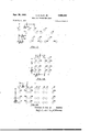
- Figure 12 is a schematic plan view of a square areal array of transducers using the spacing pattern of Figure 5 in each of two perpendicular directions;
- Figure 13 is a similar schematic plan view of a rectangular array of transducers
- Figure 14 is a schematic elevational view showing a seismic prospecting arrangement in which a plurality of shot points and a plurality of geophones are used, with the spacing between shot points being incommensurable with the spacing between geophones;
- Figure 15 is a similar elevational view showing the equivalence of the arrangement of Figure 14 to one using an incommensurable null spacing of geophones.
- FIG. 1 a portion of a conventional multiple geophone spread is shown. Usually at least twelve channels will be used in the spread but only three geophone channels are represented in the figure.
- the geophones 21 are placed upon or embedded in the surface of the ground 20 with the separate geophone groups 22. 23, and 24 each positioned at a desired detection station along the profile being prospected. The geophones in each group are evenly separated by a distance d. Suitable connection is made between each of the geophone groups 22, 23, and 24 and separate recording channels in the seismic recording apparatus by means of separate conductors 25, 26, and 27 in a cable 28.
- the geophones in the array are not spaced evenly.
- consideration is given to the longest wave length of horizontally traveling interfering energy that is to be suppressed.
- This wave- Patented Sept. 29, 1959 length is given the designation A.
- the length of each unit of the array is then determined by the relationship A n l Where "i the num Qt. eop n snherent, l if each set consists of two geophones thc unit. extends over; /z. wave length. If; three geophones. are; used. in; each set the set will. extend over /3 of a wave length and the; phones; w ll e p ced. /3.
- the spacing; between sets is. then selected to be incommensurable with the spacing between geophones within the sets. Conyeniently the spacing between sets can differ from the spacing between geophones by a function of a small prime number, for example the half power of 2, 3, 5 7, 1,1, or l3 and so on.
- the technique, for determining the, wave lengths of interfering energy from conventional S eismograrns is well known to those skilled in the art of seismic prospecting and need not be elaborated upon here.
- FIG 2 an array of four geophones is shown, all connected to the same conductor a.
- Geophones 1 and 2 .a1'e wave length apart, geophones 3 and 4 are also /2 wave length apart, and geophones, l and 3, are separa y the dis nc Alternatively the distance between geophones 1 and 2' could be i i
- FIG 3 Another six-geophone array is depicted in Figure 3 In this. array three sets of geophones areused, the spacing between the geophones in each set and the spacings bebetween the geophones in each set and the spacing: bespaeing between geophones 31 and 32, between geophones 33 and 34-, and between geophones 35 and 36.
- FIG. 4 is shown a similar array using three geophones in each set. Geophones 41, 42, and 43 are separated from each other by /3 wave length and geophones 44, 45, and 46 are similarly separated from each other by 6 wave length.
- the initial geophones of the two sets, i.e., geophones 41 and 44, are separated from each other by the distance in Figure 5 is shown a schematic plan view of a geophone array utilizing eight geophones which consists of two of the units of Figure 2 with the first geophone 5 of the second unit being separated from the first geophone 1 of the first unit by the distance N
- the sixteen-geophone array of Figure 6 as will be seen from the exploded view of Figure 7, consists of the eight-geophone array of Figure 5 repeated with the first geophone 9 of the second group of eight spaced from the first geophone 1 of the first group of eight by the distance A M1
- the separation between geophones in the sixteen-geoa eaee phone array is expressed in decimal fractions of a wave length
- Figure 13 shows a rectangular areal pattern in which thegeophones 1 through 8 are spaced from each other in the same manner as in Figure '5 and the rows containing the geophones 1a through 8a, lb through 85, and 10 through 80 are spaced from the first row in the same ratio as'geophones 1 and 9 in Figure 6
- a rectangular array of the type shown in Figure 13 is also useful .for other types of transducerssuch as loud speakers, other acoustic generators, acoustic detectors, and electromagnetic wave antennas, when it is desired to produce a narrow beam of selected directivity.
- a directional array of this type would have considerable advantage over arrays that depend upon operating the different transdulcers at difierent lev els in order to obtain the desired directivity.
- all of the transducers can be identical and can be driven in the same phase and at the same operating level, thus greatly simplifying the setting up of such an array.
- FIG. 14 Still another modification of the invention is illustrated in Figure 14 wherein two or more shot holes 61 and 62 are spaced from each other on the earths surface 60 a selected distance x and two or more geophones 65 and 66 are separated from each other a distance y which is incommensurable with the distance x, the charges in the two shot holes being detonated simultaneously and the outputs of the geophones 65 and 66 being combined.
- an apparatus for detecting seismic signals which comprises at least two sets of seismic transducers, a plurality of seismic transducers in each set arranged in a line, adjacent transducers in each set being spaced by a selected distance, each set pointing in the same direction, the transducers in each set being spaced from the transducers in each other set by a distance incommensurable with said first selected distance, and means combining the outputs of said transducers.
Description
Sept. 29, 1959 v c, s, CLAY, JR 2,906,363
MULTIPLE TRANSDUCER ARRAY I Filed May a, 195; s Sheets-Sheet 1 RECORDER =T0 RECORDER 'b 3 d A? Clarence 8. Clay Jr. Inventor Sept. 29; 1959 c. s. CLAY, JR 7 2,906,363
' MULTIPLE TRANSDUCER ARRAY Filed May 6. 1955 t 5 Sheets-Sheet 3 A 2 lb 26 353 (52 d4 5t) 77 C57 66 i 68 -7 Ic 6c c4c .IAI. A .J
FIG-I2 b d' 6) 5 00 00 5 0 C) (5 0 0 0 0 c5 Clarence S. Clay Jr. Inventor BWJ 274 {Attorney Sept. 29, 1959 c. 's. CLAY, JR
MULTIPLE TRANSDUCER ARRAY Filed May 6, 1955 0 4'0 o Io 180 FREQUENCX CYCLES PER SECOND OUTPUT PER GEOPHONE O I I I I l 0 20 4O 6O 80 I00 FREQUENCY, CYCLES PER SECOND OUTPUT PER GEOPHONEQ4 0 4'0 ab :20 lo FREQUENCX CYCLES PER SECOND o I l o 20 4'0 60 so I00 FREQUENCY, CYCLES PER SECOND OUTPUT PER GEOPHONE Clarence S. Clay, Jr
5 Sheets-Sheet 4 FIG-9 FIG-IO FIGE-II Inventor Sept. 29, 1959 s. CLAY, JR 2,90
MULTIPLE TRANSDUCER ARRAY Filed May 6, 1955 5 Sheets-Sheet 5 so, 6.1 es as 62% FIG-I5 Clarence 8. Clay, Jr. Inventor BYWJJ. 77 Attorney MULTIPLE TRANSDUCER Y Clarence S. Clay, Jr., Tulsa, Okla., assignor, by mesne assignments, to Jersey Production Research Company Application May 6, 1955, Serial No. 506,615
4 Claims. (Cl. 181-.5)
This invention concerns improvements in the transmitting and receiving of waveform signals, especially with respect to improving the directivity of an array of transducers. The invention is of particular utility in the are of seismic prospecting, having application to the use of a pattern of geophones or of shot holes that will furnish a broad band of reduction or rejection of horizontally traveling seismic interferences.
In the art of seismic prospecting, a seismic disturbance is initiated at a selected point in or on the earths surface, as for example by detonating an explosive charge in a shot hole, and the resulting waves which travel down to the underlying strata and are reflected upward are detected by geophones at a number of points spread out in a selected pattern on the earths surface. By determining the arrival time of the waves at the various detection points and knowing the seismic wave velocities in the various earth layers, it is possible to estimate the depths of the several reflecting substrata. Although it is theoretically possible to time the arrival of a reflected seismic wave by the use of a single geophone and recording device, in practice it is usually diflicult and sometimes impossible to pick out indicated reflection waves from a number of other earth vibrations that are detected and recorded at the same time. Therefore the usual practice is to employ a plurality of seismometers spread over a considerable distance along the earths surface in a selected pattern as just described and to make a plurality of traces in side-by-side relation on a single chart for purposes of comparison, since a reflection from a well-defined stratum will appear on the record as a wave form of increased amplitude on all of the traces in some definite time relation, thus permitting the reflection to be lined up on the record.
It has been found that when difliculty is encountered in obtaining suitable reflections on the record in some prospecting areas significant improvements in the ratio of reflection to non-reflection energy or, in other words, in the ratio of essentially vertical-traveling reflection energy to essentially horizontal-traveling interference energy can often be obtained by using a plurality of geophones at each detection station connected so that their outputs add together, the combined signal being recorded as a single trace on the record. This serves to average out some of the complex earth motions associated with the seismic disturbance and thus give a simpler record. Nevertheless, such use of multiple geophones has left much to be desired.
It is an object of the present invention to provide an arrangement of geophones wherein the geophones are so spaced that the response of the array to horizontally traveling transients will be substantially less than that obtained with a conventional array of evenly spaced geophones, thus still further improving the ratio of essentially vertically traveling reflection energy to essentially horizontally traveling interfering energy.
In accordance with the present invention an array of geophones is used comprising a plurality of sets of uniformly spaced geophones with non-uniform spacing be tween the sets so that with the overall array the null wave length characteristics of the sets will be incommensurable with each other.
Alternatively or in conjunction with such an array of geophones a desired directivity of seismic waves can be obtained by utilizing an array of seismic shot holes spaced in accordance with the principles of this invention.
In a broader aspect of the invention the same princi- 0 ples that apply tothe design of such geophone arrays are applicable to arrays of other transducers such as microphones, acoustic generators and pickups, loud speakers, electromagnetic wave antennas and the like.
The nature and objectives of the invention are more clearly understood when reference is made to the accompanying drawings in which:
' Figure 1 is a schematic diagram of a portion of a conventional multiple geophone spread;
Figure 2 is a schematic plan view of the simplest embodiment of a geophone array in accordance with the present invention utilizing four geophones with two geophones in each set;
Figure 3 is a schematic plan view showing an array utilizing two geophones in each of three sets;
Figure 4 is a schematic plan view of an array utilizing three geophones in each of two sets;
Figure 5 is a schematic plan view of an embodiment of the invention utilizing eight geophones in the array;
Figure 6 is a schematic plan view showing an array in which a total of sixteen geophones is used;
Figure 7 is an exploded presentation of the diagram of Figure 6 showing the development of the geophone spacing;
' Figures 8 and 9 constitute a graphical analysis of the response characteristics of a geophone array employing evenly spaced geophones;
Figures 10 and 11 constitute a graphical analysis of the response characteristics of an array utilizing sixteen geophones spaced in accordance with the present invention;
Figure 12 is a schematic plan view of a square areal array of transducers using the spacing pattern of Figure 5 in each of two perpendicular directions;
Figure 13 is a similar schematic plan view of a rectangular array of transducers;
Figure 14 is a schematic elevational view showing a seismic prospecting arrangement in which a plurality of shot points and a plurality of geophones are used, with the spacing between shot points being incommensurable with the spacing between geophones; and
Figure 15 is a similar elevational view showing the equivalence of the arrangement of Figure 14 to one using an incommensurable null spacing of geophones.
In Figure 1 a portion of a conventional multiple geophone spread is shown. Usually at least twelve channels will be used in the spread but only three geophone channels are represented in the figure. The geophones 21 are placed upon or embedded in the surface of the ground 20 with the separate geophone groups 22. 23, and 24 each positioned at a desired detection station along the profile being prospected. The geophones in each group are evenly separated by a distance d. Suitable connection is made between each of the geophone groups 22, 23, and 24 and separate recording channels in the seismic recording apparatus by means of separate conductors 25, 26, and 27 in a cable 28.
In accordance with the present invention, as already stated, the geophones in the array are not spaced evenly. To determine the geophone spacing, consideration is given to the longest wave length of horizontally traveling interfering energy that is to be suppressed. This wave- Patented Sept. 29, 1959 length is given the designation A. The length of each unit of the array is then determined by the relationship A n l Where "i the num Qt. eop n snherent, l if each set consists of two geophones thc unit. extends over; /z. wave length. If; three geophones. are; used. in; each set the set will. extend over /3 of a wave length and the; phones; w ll e p ced. /3. of ave e th; aP r In the same manner with four geophones per unit the set. would, be %.A in length, The spacing; between sets is. then selected to be incommensurable with the spacing between geophones within the sets. Conyeniently the spacing between sets can differ from the spacing between geophones by a function of a small prime number, for example the half power of 2, 3, 5 7, 1,1, or l3 and so on. The technique, for determining the, wave lengths of interfering energy from conventional S eismograrns is well known to those skilled in the art of seismic prospecting and need not be elaborated upon here.
In Figure 2 an array of four geophones is shown, all connected to the same conductor a. Geophones 1 and 2 .a1'e wave length apart, geophones 3 and 4 are also /2 wave length apart, and geophones, l and 3, are separa y the dis nc Alternatively the distance between geophones 1 and 2' could be i i Another six-geophone array is depicted in Figure 3 In this. array three sets of geophones areused, the spacing between the geophones in each set and the spacings bebetween the geophones in each set and the spacing: bespaeing between geophones 31 and 32, between geophones 33 and 34-, and between geophones 35 and 36. is, in each' instance /2 wave length, while geophones 31, 33 and 155 are spaced from each otherby 1. 2\/ times the wave length. As in Figure :2, all six geophones are connected to the same conductor to feed a single trace. on the recorder, but the connections are not shown.
In Figure 4 is shown a similar array using three geophones in each set. Geophones 41, 42, and 43 are separated from each other by /3 wave length and geophones 44, 45, and 46 are similarly separated from each other by 6 wave length. The initial geophones of the two sets, i.e., geophones 41 and 44, are separated from each other by the distance in Figure 5 is shown a schematic plan view of a geophone array utilizing eight geophones which consists of two of the units of Figure 2 with the first geophone 5 of the second unit being separated from the first geophone 1 of the first unit by the distance N In a similar manner the sixteen-geophone array of Figure 6, as will be seen from the exploded view of Figure 7, consists of the eight-geophone array of Figure 5 repeated with the first geophone 9 of the second group of eight spaced from the first geophone 1 of the first group of eight by the distance A M1 The separation between geophones in the sixteen-geoa eaee phone array is expressed in decimal fractions of a wave length in Figure 6. As in the previous arrays all of the geophones are connected to a single conductor leading go the recorder although the connections are not shown ere.
Referring now to Figures 8 to 11 inclusive the response characteristics of a geophone array employing sixteen evenly spaced geophones and the response characteristics of an array utilizing sixteen geophones spaced as. in Figure 6. are graphically analyzed and compared.
21: Fi ure 3isr1ib$ ntbd a rap ial ehtesentatibfi. o the assumed amplitude versus frequency spectrum of an interfering transient signal identified by line SI and the amplitude versus frequency response, curve, identified by line 52 of an array of sixteen evenly spaced geophones. It will be noted that the geophone array has response nulls at 40, 80, and cycles per second.
Cu e. 5 hows.v he respo se. of e one rr qntinnbi s W v o ea h. par cu f u cy r t e ran e 0t 0 0. out 1 cy e Per I1 Since he p rpos Qt u 5. t q-m a e ma ni e e elati Pha e o e out s snb dn l br gn o the urv a sho n a P i e m i he lysi use c ns r ctin ure 8 is based an analogy to the ponse PM"? Of an. @l a1fi t d hence curve 51 can be treated as the assumed spectrum? of atransient signal that is to be filtered out. It is more convenient to handle the analysis on the basis of fre-. quer eies rather than wave lengths although it is to be remembered that it the wave lengths of the interfering waves that are of principal concern. It is merely n ece? sary to assume uniform velocities of wave propagation to handle the analysis on a frequency basis.
' By determining the product of the geophone array response curve 52 and the amplitude of. the transient 51 at each frequency, the curve 53 in Figure 9 is obtained. For comparison line 54 is presented showing the amplitude versus frequency for a desired reflection having a frequency of :50: cycles. It will be noted fro rn curve 53 that the. interfering signal has an appreciable amplitude at il 50 W qu y a In Figure 10 is presented an amplitude versus frequency curve 55 for the geophone array'of Figure 5. The amplitude versus frequency curve forthe interfering sigrial is again represented by line 51. Deriving Figure 11 from Figure 10 in the same manher that Figure 9 was derived from Figure 8, it will be seen that the amplitude versusfrequency curs/e56 is much improved over the curve 53 of Figure 9 and that the amplitude of the in t erfering signal is greatly reduced in the 50 cycle range.
The same principles of spacing as are illustrated in Figures 2 through 7 can also be employed for areal'a'rrays. For example a square areal pattern can be used as shown in Figure 12 in which the spacing pattern of Figure 5 is us e d for the separation of the geophones in each row as well as for the spacing between the rows. Thus geophones 1 and 1b are spaced from each other the saine distance as geophones 1 and 2, geophones 1a and 1c are spaced from each other the same distance as geophones Sand}? and geophones 1' andla are spaced from each other the same distance'as geophones 1 and 3;.
Similarly Figure 13 shows a rectangular areal pattern in which thegeophones 1 through 8 are spaced from each other in the same manner as in Figure '5 and the rows containing the geophones 1a through 8a, lb through 85, and 10 through 80 are spaced from the first row in the same ratio as'geophones 1 and 9 in Figure 6 A rectangular array of the type shown in Figure 13 is also useful .for other types of transducerssuch as loud speakers, other acoustic generators, acoustic detectors, and electromagnetic wave antennas, when it is desired to produce a narrow beam of selected directivity. A directional array of this type would have considerable advantage over arrays that depend upon operating the different transdulcers at difierent lev els in order to obtain the desired directivity. In an array spaced in accordance with Figure 13 or in accordance with similar patterns using the incommensurable null principle, all of the transducers can be identical and can be driven in the same phase and at the same operating level, thus greatly simplifying the setting up of such an array.
Still another modification of the invention is illustrated in Figure 14 wherein two or more shot holes 61 and 62 are spaced from each other on the earths surface 60 a selected distance x and two or more geophones 65 and 66 are separated from each other a distance y which is incommensurable with the distance x, the charges in the two shot holes being detonated simultaneously and the outputs of the geophones 65 and 66 being combined.
Comparison of the diagrams of Figures 14 and 15 will readily reveal that the arrangement of Figure 14 is equivalent to an arrangement wherein only one shot hole 62 is used and four "geophones'are' employed in the manner of Figure 2, geophones 65 and 66 being spaced apart the same distance y as for the spacing of geophones 63 and 64, and geophones 63 and 65 being spaced the distance x from each other. Considering the ray paths from each of the shot holes to a reflecting layer 69 and from there to each of the geophones it will be seen that the paths, and therefore the travel times of the waves, from shot hole 62 to point e to geophone 65 and from shot hole 63 to point f to geophone 66 of Figure 15 are of the same length as the ray paths 61 to a to 63 and 61 to c to 64, respectively, of Figure 14. The travel paths 62 to b to 63 and 62 to d to 64 of Figure 14 would of course be the same in Figure 15, but are omitted there to clarify the illustration.
As previously stated, it is also within the contemplation of this invention to use a plurality of shot holes spaced in accordance with the incommensurable null principles set forth herein, as Well as such spaced shot holes in conjunction with geophone arrays of the type herein described. In the latter instance the shot hole spacing will be such that each null of the shot hole spacing would be incommensurable with each null of the geophone pattern.
It will be apparent to persons skilled in the art that many modifications of this invention are possible without departing from its scope. It is therefore intended that the invention not be limited to the specific examples presented. The scope of the invention is defined by the following claims.
What is claimed is:
1. In the art of seismic prospecting an apparatus for detecting seismic signals which comprises at least two sets of seismic transducers, a plurality of seismic transducers in each set arranged in a line, adjacent transducers in each set being spaced by a selected distance, each set pointing in the same direction, the transducers in each set being spaced from the transducers in each other set by a distance incommensurable with said first selected distance, and means combining the outputs of said transducers.
2. An apparatus as defined in claim 1 in which the sets of transducers are arranged along a common line.
3. An apparatus as defined in claim 1 in which the sets are arranged in parallel lines.
4. An apparatus as defined in claim 1 in which the seismic transducers are geophones.
References Cited in the file of this patent UNITED STATES PATENTS 2,029,015 Bohm Ian. 28, 1936 2,180,949 Blau et al. Nov. 21, 1939 2,232,612 Klipsch Feb. 18, 1941 2,232,613 Klipsch Feb. 18, 1941 2,580,636 Wolf Jan. 1, 1952 2,586,731 Simon et al. Feb. 19, 1952 2,759,551 Carlisle et al Aug. 21, 1956
Priority Applications (1)
| Application Number | Priority Date | Filing Date | Title |
|---|---|---|---|
| US506615A US2906363A (en) | 1955-05-06 | 1955-05-06 | Multiple transducer array |
Applications Claiming Priority (1)
| Application Number | Priority Date | Filing Date | Title |
|---|---|---|---|
| US506615A US2906363A (en) | 1955-05-06 | 1955-05-06 | Multiple transducer array |
Publications (1)
| Publication Number | Publication Date |
|---|---|
| US2906363A true US2906363A (en) | 1959-09-29 |
Family
ID=24015319
Family Applications (1)
| Application Number | Title | Priority Date | Filing Date |
|---|---|---|---|
| US506615A Expired - Lifetime US2906363A (en) | 1955-05-06 | 1955-05-06 | Multiple transducer array |
Country Status (1)
| Country | Link |
|---|---|
| US (1) | US2906363A (en) |
Cited By (31)
| Publication number | Priority date | Publication date | Assignee | Title |
|---|---|---|---|---|
| US3130410A (en) * | 1961-10-23 | 1964-04-21 | Itt | Space coded linear array antenna |
| US3137363A (en) * | 1957-10-28 | 1964-06-16 | Geophysical Res Corp | Method for multiple geophone recording in seismic prospecting |
| US3189870A (en) * | 1960-12-30 | 1965-06-15 | Shell Oil Co | Geophone spread for seismic systems |
| US3280936A (en) * | 1961-03-07 | 1966-10-25 | Petty Geophysical Eng Co | Method for seismic surveying |
| US3286228A (en) * | 1962-01-19 | 1966-11-15 | Seismograph Service Corp | Method of transmitting and receiving signals in separate frequency parts to reduce undesired components |
| US3335401A (en) * | 1966-01-07 | 1967-08-08 | Mobil Oil Corp | Noise-filtered detection of marine seismic signals |
| US3349866A (en) * | 1963-04-19 | 1967-10-31 | Exxon Production Research Co | Directive transducer array for seismic exploration |
| US3386076A (en) * | 1966-05-06 | 1968-05-28 | Vining T. Reynolds | System for separating the in-phase waves from the out-of-phase waves detected by plural geophones |
| US3400783A (en) * | 1966-12-27 | 1968-09-10 | Mobil Oil Corp | Centroid spaced seismic transducer array |
| US3479638A (en) * | 1968-07-29 | 1969-11-18 | Us Interior | Beamforming in seismic surveying |
| US3740751A (en) * | 1972-06-19 | 1973-06-19 | Itt | Wideband dual-slot waveguide array |
| US3747055A (en) * | 1971-06-16 | 1973-07-17 | Texaco Inc | High resolution shooting with space domain filtering |
| US3747056A (en) * | 1971-06-16 | 1973-07-17 | Texaco Inc | High resolution reflection shooting with data mixing |
| US3760347A (en) * | 1971-06-16 | 1973-09-18 | Texaco Inc | High resolution reflection shooting |
| US3877033A (en) * | 1973-08-15 | 1975-04-08 | Hillel Unz | Nonuniformly optimally spaced array with uniform amplitudes |
| US4011539A (en) * | 1975-12-22 | 1977-03-08 | Texaco Inc. | Seismic detector arrays |
| US4320471A (en) * | 1977-10-29 | 1982-03-16 | Deutsche Texaco Aktiengesellschaft | Seismic surveying method |
| US4499565A (en) * | 1980-01-10 | 1985-02-12 | Atlantic Richfield Company | Method and apparatus for recording broad-band seismic data |
| WO1985001360A1 (en) * | 1983-09-12 | 1985-03-28 | Geosource Inc. | Method and apparatus for multi-line seismic exploration |
| US4758998A (en) * | 1986-05-02 | 1988-07-19 | Amoco Corporation | Methods for attenuation of horizontally traveling seismic waves |
| FR2690033A1 (en) * | 1992-04-14 | 1993-10-15 | Thomson Csf | Linear aerial for underwater detection - includes groups of sensors with weighting applied to outputs in order to minimise noise effects |
| US6052333A (en) * | 1992-10-23 | 2000-04-18 | Texaco Inc. | Method for seismic antenna illumination of subterranean feature for display and evaluation |
| WO2011156491A1 (en) | 2010-06-09 | 2011-12-15 | Conocophillips Company | Seismic data acquisition using designed non-uniform receiver spacing |
| US20120236687A1 (en) * | 2011-03-18 | 2012-09-20 | Owen Thomas E | Directional Seismic Sensor Array |
| WO2016009270A1 (en) * | 2014-07-17 | 2016-01-21 | Cgg Services Sa | Systematic departure from pattern regularity in seismic data acquisition |
| US20160109595A1 (en) * | 2014-10-20 | 2016-04-21 | Ion Geophysical Corporation | Noise Removal in Non-Uniformly Spaced Seismic Receiver Arrays |
| US10809402B2 (en) | 2017-05-16 | 2020-10-20 | Conocophillips Company | Non-uniform optimal survey design principles |
| US11016208B2 (en) * | 2015-06-01 | 2021-05-25 | Pgs Geophysical As | Highly-sparse seabed acquisition designs adapted for imaging geological structure and/or monitoring reservoir production |
| US11294088B2 (en) | 2014-12-18 | 2022-04-05 | Conocophillips Company | Methods for simultaneous source separation |
| US11481677B2 (en) | 2018-09-30 | 2022-10-25 | Shearwater Geoservices Software Inc. | Machine learning based signal recovery |
| US11543551B2 (en) | 2015-09-28 | 2023-01-03 | Shearwater Geoservices Software Inc. | 3D seismic acquisition |
Citations (7)
| Publication number | Priority date | Publication date | Assignee | Title |
|---|---|---|---|---|
| US2029015A (en) * | 1929-08-27 | 1936-01-28 | Telefunken Gmbh | Antenna |
| US2180949A (en) * | 1936-07-11 | 1939-11-21 | Standard Oil Dev Co | Feedover device |
| US2232613A (en) * | 1937-05-01 | 1941-02-18 | E E Rosaire | Seismic prospecting |
| US2232612A (en) * | 1937-05-01 | 1941-02-18 | E E Rosaire | Recording seismic waves |
| US2580636A (en) * | 1945-03-01 | 1952-01-01 | Texas Co | Reflection seismic exploration |
| US2586731A (en) * | 1949-03-11 | 1952-02-19 | Socony Vacuum Oil Co Inc | Surface generation of seismic waves |
| US2759551A (en) * | 1952-03-18 | 1956-08-21 | Exxon Research Engineering Co | System for seismic exploration |
-
1955
- 1955-05-06 US US506615A patent/US2906363A/en not_active Expired - Lifetime
Patent Citations (7)
| Publication number | Priority date | Publication date | Assignee | Title |
|---|---|---|---|---|
| US2029015A (en) * | 1929-08-27 | 1936-01-28 | Telefunken Gmbh | Antenna |
| US2180949A (en) * | 1936-07-11 | 1939-11-21 | Standard Oil Dev Co | Feedover device |
| US2232613A (en) * | 1937-05-01 | 1941-02-18 | E E Rosaire | Seismic prospecting |
| US2232612A (en) * | 1937-05-01 | 1941-02-18 | E E Rosaire | Recording seismic waves |
| US2580636A (en) * | 1945-03-01 | 1952-01-01 | Texas Co | Reflection seismic exploration |
| US2586731A (en) * | 1949-03-11 | 1952-02-19 | Socony Vacuum Oil Co Inc | Surface generation of seismic waves |
| US2759551A (en) * | 1952-03-18 | 1956-08-21 | Exxon Research Engineering Co | System for seismic exploration |
Cited By (42)
| Publication number | Priority date | Publication date | Assignee | Title |
|---|---|---|---|---|
| US3137363A (en) * | 1957-10-28 | 1964-06-16 | Geophysical Res Corp | Method for multiple geophone recording in seismic prospecting |
| US3189870A (en) * | 1960-12-30 | 1965-06-15 | Shell Oil Co | Geophone spread for seismic systems |
| US3280936A (en) * | 1961-03-07 | 1966-10-25 | Petty Geophysical Eng Co | Method for seismic surveying |
| US3130410A (en) * | 1961-10-23 | 1964-04-21 | Itt | Space coded linear array antenna |
| US3286228A (en) * | 1962-01-19 | 1966-11-15 | Seismograph Service Corp | Method of transmitting and receiving signals in separate frequency parts to reduce undesired components |
| US3349866A (en) * | 1963-04-19 | 1967-10-31 | Exxon Production Research Co | Directive transducer array for seismic exploration |
| US3335401A (en) * | 1966-01-07 | 1967-08-08 | Mobil Oil Corp | Noise-filtered detection of marine seismic signals |
| US3386076A (en) * | 1966-05-06 | 1968-05-28 | Vining T. Reynolds | System for separating the in-phase waves from the out-of-phase waves detected by plural geophones |
| US3400783A (en) * | 1966-12-27 | 1968-09-10 | Mobil Oil Corp | Centroid spaced seismic transducer array |
| US3479638A (en) * | 1968-07-29 | 1969-11-18 | Us Interior | Beamforming in seismic surveying |
| US3760347A (en) * | 1971-06-16 | 1973-09-18 | Texaco Inc | High resolution reflection shooting |
| US3747055A (en) * | 1971-06-16 | 1973-07-17 | Texaco Inc | High resolution shooting with space domain filtering |
| US3747056A (en) * | 1971-06-16 | 1973-07-17 | Texaco Inc | High resolution reflection shooting with data mixing |
| US3740751A (en) * | 1972-06-19 | 1973-06-19 | Itt | Wideband dual-slot waveguide array |
| US3877033A (en) * | 1973-08-15 | 1975-04-08 | Hillel Unz | Nonuniformly optimally spaced array with uniform amplitudes |
| US4011539A (en) * | 1975-12-22 | 1977-03-08 | Texaco Inc. | Seismic detector arrays |
| US4320471A (en) * | 1977-10-29 | 1982-03-16 | Deutsche Texaco Aktiengesellschaft | Seismic surveying method |
| US4499565A (en) * | 1980-01-10 | 1985-02-12 | Atlantic Richfield Company | Method and apparatus for recording broad-band seismic data |
| WO1985001360A1 (en) * | 1983-09-12 | 1985-03-28 | Geosource Inc. | Method and apparatus for multi-line seismic exploration |
| US4758998A (en) * | 1986-05-02 | 1988-07-19 | Amoco Corporation | Methods for attenuation of horizontally traveling seismic waves |
| FR2690033A1 (en) * | 1992-04-14 | 1993-10-15 | Thomson Csf | Linear aerial for underwater detection - includes groups of sensors with weighting applied to outputs in order to minimise noise effects |
| US6052333A (en) * | 1992-10-23 | 2000-04-18 | Texaco Inc. | Method for seismic antenna illumination of subterranean feature for display and evaluation |
| US9846248B2 (en) | 2010-06-09 | 2017-12-19 | Conocophillips Company | Seismic data acquisition using designed non-uniform receiver spacing |
| US10823867B2 (en) * | 2010-06-09 | 2020-11-03 | Conocophillips Company | Seismic data acquisition using designed non-uniform receiver spacing |
| US10989826B2 (en) * | 2010-06-09 | 2021-04-27 | Conocophillips Company | Seismic data acquisition using designed non-uniform receiver spacing |
| AU2011264929B2 (en) * | 2010-06-09 | 2014-08-07 | Shearwater Geoservices Software Inc. | Seismic data acquisition using designed non-uniform receiver spacing |
| WO2011156491A1 (en) | 2010-06-09 | 2011-12-15 | Conocophillips Company | Seismic data acquisition using designed non-uniform receiver spacing |
| EP2580610A4 (en) * | 2010-06-09 | 2017-07-26 | ConocoPhillips Company | Seismic data acquisition using designed non-uniform receiver spacing |
| US20120236687A1 (en) * | 2011-03-18 | 2012-09-20 | Owen Thomas E | Directional Seismic Sensor Array |
| US8542556B2 (en) * | 2011-03-18 | 2013-09-24 | Thomas E. Owen | Directional seismic sensor array |
| WO2016009270A1 (en) * | 2014-07-17 | 2016-01-21 | Cgg Services Sa | Systematic departure from pattern regularity in seismic data acquisition |
| US20160109595A1 (en) * | 2014-10-20 | 2016-04-21 | Ion Geophysical Corporation | Noise Removal in Non-Uniformly Spaced Seismic Receiver Arrays |
| US9903968B2 (en) * | 2014-10-20 | 2018-02-27 | Ion Geophysical Corporation | Noise removal in non-uniformly spaced seismic receiver arrays |
| US11294088B2 (en) | 2014-12-18 | 2022-04-05 | Conocophillips Company | Methods for simultaneous source separation |
| US11740375B2 (en) | 2014-12-18 | 2023-08-29 | Shearwater Geoservices Software Inc. | Methods for simultaneous source separation |
| US11016208B2 (en) * | 2015-06-01 | 2021-05-25 | Pgs Geophysical As | Highly-sparse seabed acquisition designs adapted for imaging geological structure and/or monitoring reservoir production |
| US11604297B2 (en) | 2015-06-01 | 2023-03-14 | Pgs Geophysical As | Highly-sparse seabed acquisition designs adapted for imaging geological structure and/or monitoring reservoir production |
| US11543551B2 (en) | 2015-09-28 | 2023-01-03 | Shearwater Geoservices Software Inc. | 3D seismic acquisition |
| US10809402B2 (en) | 2017-05-16 | 2020-10-20 | Conocophillips Company | Non-uniform optimal survey design principles |
| US11409014B2 (en) | 2017-05-16 | 2022-08-09 | Shearwater Geoservices Software Inc. | Non-uniform optimal survey design principles |
| US11835672B2 (en) | 2017-05-16 | 2023-12-05 | Shearwater Geoservices Software Inc. | Non-uniform optimal survey design principles |
| US11481677B2 (en) | 2018-09-30 | 2022-10-25 | Shearwater Geoservices Software Inc. | Machine learning based signal recovery |
Similar Documents
| Publication | Publication Date | Title |
|---|---|---|
| US2906363A (en) | Multiple transducer array | |
| US3096846A (en) | Method and apparatus for seismographic exploration | |
| US2732906A (en) | Seismic surveying | |
| US2390187A (en) | Seismic surveying | |
| US5511039A (en) | Method of performing high resolution crossed-array seismic surveys | |
| US3259878A (en) | Method of controlling the seismic signal in exploration | |
| AU3767501A (en) | Seismic source arrays | |
| US3719924A (en) | Anti-aliasing of spatial frequencies by geophone and source placement | |
| US4004267A (en) | Discrete frequency seismic exploration using non uniform frequency spectra | |
| US4001770A (en) | Roll-a-long three-dimensional common depth point exploration | |
| AU721305B2 (en) | Method for sorting seismic data | |
| US2747172A (en) | Geophone arrangement for seismic prospecting | |
| US4363113A (en) | Seismic exploration with simulated plane waves | |
| US3731270A (en) | Seismic exploration using the common reflection point technique | |
| US3867713A (en) | Multifold seismic exploration over purposefully crooked traverses | |
| US4509149A (en) | Directional long array for logging vertical boundaries | |
| US3747056A (en) | High resolution reflection shooting with data mixing | |
| US4567582A (en) | Direct determination of stacking velocities in three dimensional seismic prospecting | |
| US3753222A (en) | Three dimensional common depth point exploration | |
| US2759551A (en) | System for seismic exploration | |
| US3349866A (en) | Directive transducer array for seismic exploration | |
| US2654874A (en) | Seismic exploration system | |
| US3088541A (en) | Seismic exploration | |
| US3601790A (en) | Common depth point seismic prospecting | |
| US5285423A (en) | Method of broadline seismic data acquisition |