US290507A - westinahouse - Google Patents
westinahouse Download PDFInfo
- Publication number
- US290507A US290507A US290507DA US290507A US 290507 A US290507 A US 290507A US 290507D A US290507D A US 290507DA US 290507 A US290507 A US 290507A
- Authority
- US
- United States
- Prior art keywords
- water
- valve
- steam
- chambers
- pistons
- Prior art date
- Legal status (The legal status is an assumption and is not a legal conclusion. Google has not performed a legal analysis and makes no representation as to the accuracy of the status listed.)
- Expired - Lifetime
Links
- XLYOFNOQVPJJNP-UHFFFAOYSA-N water Substances O XLYOFNOQVPJJNP-UHFFFAOYSA-N 0.000 description 30
- 230000005494 condensation Effects 0.000 description 3
- 238000009833 condensation Methods 0.000 description 3
- 238000010276 construction Methods 0.000 description 2
- 230000000694 effects Effects 0.000 description 2
- 230000005484 gravity Effects 0.000 description 2
- 230000001105 regulatory effect Effects 0.000 description 2
- 230000001276 controlling effect Effects 0.000 description 1
- 238000010438 heat treatment Methods 0.000 description 1
- 239000002184 metal Substances 0.000 description 1
- 238000005192 partition Methods 0.000 description 1
- 239000013049 sediment Substances 0.000 description 1
- 239000002351 wastewater Substances 0.000 description 1
Images


Classifications
-
- F—MECHANICAL ENGINEERING; LIGHTING; HEATING; WEAPONS; BLASTING
- F22—STEAM GENERATION
- F22D—PREHEATING, OR ACCUMULATING PREHEATED, FEED-WATER FOR STEAM GENERATION; FEED-WATER SUPPLY FOR STEAM GENERATION; CONTROLLING WATER LEVEL FOR STEAM GENERATION; AUXILIARY DEVICES FOR PROMOTING WATER CIRCULATION WITHIN STEAM BOILERS
- F22D5/00—Controlling water feed or water level; Automatic water feeding or water-level regulators
- F22D5/08—Controlling water feed or water level; Automatic water feeding or water-level regulators with float-actuated valves
-
- Y—GENERAL TAGGING OF NEW TECHNOLOGICAL DEVELOPMENTS; GENERAL TAGGING OF CROSS-SECTIONAL TECHNOLOGIES SPANNING OVER SEVERAL SECTIONS OF THE IPC; TECHNICAL SUBJECTS COVERED BY FORMER USPC CROSS-REFERENCE ART COLLECTIONS [XRACs] AND DIGESTS
- Y10—TECHNICAL SUBJECTS COVERED BY FORMER USPC
- Y10T—TECHNICAL SUBJECTS COVERED BY FORMER US CLASSIFICATION
- Y10T137/00—Fluid handling
- Y10T137/2931—Diverse fluid containing pressure systems
- Y10T137/2937—Gas pressure discharge of liquids feed traps [e.g., to boiler]
- Y10T137/2947—Gas pressure controlled by amount of liquid in trap
- Y10T137/295—Plural trap chambers
Definitions
- My invention relates to certain improvements in mechanism for automatically supplying water to steam-boilers; and in general terms it consists of certain combinations of tivo ivaterchambers having supply and discharge ports, the latter leading to the boiler, with valve mechanism for controlling the iow of water through such ports 5 valve-governed mechanism for admitting steam-supply automatically from the boiler to the Water-chainbers iny succession, and valve mechanism controlied by water in the chambers for effecting movement of the steam-distributing valve, as hereinafter more fully described and claimed.
- A represents a cast-metal shell or case, divided in a transverse vertical chambers, A A2. Provision is made for water supply to and discharge from each of these chambers, as follows: A valvecase, B, is bolted to the side of shell A, as at b, Fig. l, such case having two valve-chambers, B B2, therein. one of which, as chamber B', communicates by passage Zi with water-chamber A', and the other, B2, communicates by a similar passage, lf, with Water-chamber A2.
- Vater-supply to these chambers is from pipe D and common passage D', by valve-governed ports t', to thef lower end oi' the valve-chambers; ordinary check-valves, d, guided by Winged stems d', being employed to close the ports b by pressure or ilovv of Water from Within, but to open under pressure oi' the supply.
- This supply may be from anysuitable source, as an elevated reservoir, street-mains, or the Waste-water pipes of a steam-heating system, whereby Water oi' condensation may be returned to the boilers, and the pressure of such supply should be sufficient to fill or nearly iill the chambers A A2.
- Tater-discharge from the chambers is from the upper end oi' valve-chambers B B ⁇ l by valve-governed poits b2 and common passage B3 to pipe B4, which leads to the boiler or boilers.
- this pipe In order to secure rapid discharge or iloiv oi water to the boiler, this pipe should be comparatively large, and, if desired, any
- checlrvalve may be placed at any convenient point in its length to prevent escape from the boiler in case it may be desired for any cause to disconnect the feed-Water mechanism.
- the ports Z1 are controlled by downwardly-seating check-valves E, adapted to open under pressure oi' water thereon from the chambers, but to close by pressure in the opposite direction.
- the valves arc guided by stems e and wings or guides e also a down# 4Wardly-projecting stem or pin, e2, from each valve E aftords a stop to prevent excessive lift of supply-valves d.
- this mechanism is placed a little above the level of the boiler, sol that Water admitted to chambers A A2, as above described, may flow, by gravity, from the chambers to 'the boiler. This can take place only when steam-pressure against such inflow is balanced or exceeded by pressure upon the Water Within chambers A A2.
- a slide-valve, l' controls steam passage through the ports i i. ln order to impart the' desired movement to this valve, a cylinder,
- N is secured on the face of seat I, an opening,V n, being made in the lower side of the cylinder-shell, to uncover the valve-seat proper.
- the upper part or body of the valve extends upward into this cylinder through the opening n, and also through an opening, r, in the shell of a tubular stem, It, which stem connects or unites two pistons, R R', formed at either end.
- An opening, r, in the tubular stem permits steam to fill its interior, such steam being supplied from the boiler by any suitable pipe-connections-for example, as indicated by the dotted lines a', Fig. 2.
- Small holes r in the piston-heads R also provide for passage of steam, in comparatively small quantities, from the interior of stem R to the spaces in cylinder N outside of the pistons. The steam-passage thus afforded will suffice to preserve equilibrium of pressure on both sides of each piston, except when steamescape may be caused from these end spaces.
- passages 2 are made from either end ofthe cylinder N, through the body of cap I to valve-chambers S-one at or near either end of the cap. 'These chambers are closed above by screw-caps S2, and below by tubular bushings S', seated in the base of the chambers S, which bushings afford seats for valves s, such valves being seated by springs s.
- Stems s2 extend downward from the valves through the bushings S, and rest at their lower ends upon or near pivoted arms T-one in each chamber A A2.
- Hollow shells T T2,or other form of float orweight, are connected to the free end of each arm T. As water rises in either chamber, these iioats will be lifted thereby, thus raising the valves s from their seats, and opening steam-escape through the passages i2 i, from the ends of cylinder N to the exhaust i.
- valve I also opens the right-hand chamber A2 to the exhaust, thereby permitting escape of any steam which may have remained therein from a previous operation. Then, during the discharge of water from the chamber A, the inflowing water passes through B2 to chamber A2. When water rises to a sufficient height in this chamber,the float T2 will be raised, the righthand valve s be opened, and the distributingvalve I will be shifted to the right, thereby admit-ting vsteam to chamber A2 and exhausting it from chamber A. Water will then flow from chamber A2 to boiler, and inflowing supply will again be directed to chamber A.
- Fig. 3 I have shown the bottom ai of the water-chambers A' A2 level, or approximately so, with the' water-passages b2 b4. If desired, this bottom may be lowered any desired distance below the water-passage-say to the bottom or base ca -and thereby form a dead-water space, in which sediment might settle.
- the holes may be stopped with screw-plugs or in other convenient way.
- I claim herein as my invention- 1. A case inclosing two separate chambers ⁇ with valve-governed water supply and discharge passages for each chamber, in combination with a steam-supply cylinder having ports communicating with both water-chambers, a valve for governing supply and eX- haust of steam through such ports, two connected pistons movable within the cylinder and carrying the distributing-valve in their movement, and valve-governed passages for escape of steam from either end of the cylinder to effect movement of the pistons and distributing-valve, substantially as set forth.
- a case inclosing two separate chambers with valve-governed water supply and discharge ports for each chamber in combination with a steam cylinder communicating with both water-chambers, a valve governing supply and exhaust of steam to and from each chamber, two pistons carrying the steam-distributing valve, such pistons being movable within the cylinder by unequal steam-pressure thereon, a valve-governed steam-escape passage communicating with each end of the cylinder, and a iioat or equivalent body in each chamber, such ioats connected with and operative in opening the valves in the escapevalves by action of the water thereon, substantially as set forth.
- a valve governing supply of steam to and exhaust from the water-chambers two pistons for operating the valve, such pistons being movable within the steamchamber by difference ofsteam-pressure thereon, valve-governed escape-passages communi eatin g with the steam-chamber, and mechanism for opening the escape-valves automatically by operation of the water in the waterchambers, substantially as set forth.
- Y 6 a valve governing supply of steam to and exhaust from the water-chambers, two pistons for operating the valve, such pistons being movable within the steamchamber by difference ofsteam-pressure thereon, valve-governed escape-passages communi eatin g with the steam-chamber, and mechanism for opening the escape-valves automatically by operation of the water in the waterchambers, substantially as set forth.
Landscapes
- Engineering & Computer Science (AREA)
- Physics & Mathematics (AREA)
- Thermal Sciences (AREA)
- Mechanical Engineering (AREA)
- General Engineering & Computer Science (AREA)
- Mechanically-Actuated Valves (AREA)
Description
(No Model.) Y 2 Sheets-Sheet 1.
" G: WESTNGHOUSE, Jr.
BQILER FEEDER'. No. 290,507. Patented Dec. 18, 1883.
(No Maciel.) l 2 Sheets-Sheet 2.
Gr. WESTINGHOUSE, Jr.
BOILER FEEDER.
No. 290,507. i Patented Deo. 18, i883.
wkwhm. ou' MU* Wma@ MPEYERS, Pmm-mmsnvben wmhmgmn, D. c,
sectional view ofthe lower portion, the plane plane by a partition, a, into two separate www,
www, @aan GEORGE VESTNGHOUSE, JR., OF PITTSBURG, PENNSYLVANIA.
BOILERAFEEDER.
SPECIFICATION forming part of Letters Patent No. 290,507, dated December 18, 1883. Application iiled September 3, 1583. (No model.)
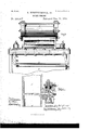
To all whom t may concern Beit known that I, GnonenWns'riNGHoUsn, J r., a citizen of the United States, residing at Pittsburg, county of Allegheny, State of Pennsylvania, have invented or discovered a new and useful improvement in Boiler-Feeders 5 and I do hereby declare the following to be a full, clear, concise, and exactdescription thereof, reference being had to the accompanying drawings, making a part of this specification, in which-like letters indicating like parts- Figure l is a view in sectional elevation of my improved mechanism. Fig. 2, Sheet 2, is a View in side elevation of the upper portion of the mechanism, and Fig. 3 is a transverse of section being in dicated by the linemv, Fig. 1.
My invention relates to certain improvements in mechanism for automatically supplying water to steam-boilers; and in general terms it consists of certain combinations of tivo ivaterchambers having supply and discharge ports, the latter leading to the boiler, with valve mechanism for controlling the iow of water through such ports 5 valve-governed mechanism for admitting steam-supply automatically from the boiler to the Water-chainbers iny succession, and valve mechanism controlied by water in the chambers for effecting movement of the steam-distributing valve, as hereinafter more fully described and claimed.
in t-he drawings, A represents a cast-metal shell or case, divided in a transverse vertical chambers, A A2. Provision is made for water supply to and discharge from each of these chambers, as follows: A valvecase, B, is bolted to the side of shell A, as at b, Fig. l, such case having two valve-chambers, B B2, therein. one of which, as chamber B', communicates by passage Zi with water-chamber A', and the other, B2, communicates by a similar passage, lf, with Water-chamber A2. Vater-supply to these chambers is from pipe D and common passage D', by valve-governed ports t', to thef lower end oi' the valve-chambers; ordinary check-valves, d, guided by Winged stems d', being employed to close the ports b by pressure or ilovv of Water from Within, but to open under pressure oi' the supply. This supply may be from anysuitable source, as an elevated reservoir, street-mains, or the Waste-water pipes of a steam-heating system, whereby Water oi' condensation may be returned to the boilers, and the pressure of such supply should be sufficient to fill or nearly iill the chambers A A2. Tater-discharge from the chambers is from the upper end oi' valve-chambers B B`l by valve-governed poits b2 and common passage B3 to pipe B4, which leads to the boiler or boilers. In order to secure rapid discharge or iloiv oi water to the boiler, this pipe should be comparatively large, and, if desired, any
ordinary checlrvalve may be placed at any convenient point in its length to prevent escape from the boiler in case it may be desired for any cause to disconnect the feed-Water mechanism. The ports Z1 are controlled by downwardly-seating check-valves E, adapted to open under pressure oi' water thereon from the chambers, but to close by pressure in the opposite direction. The valves arc guided by stems e and wings or guides e also a down# 4Wardly-projecting stem or pin, e2, from each valve E aftords a stop to prevent excessive lift of supply-valves d.
In use, this mechanism is placed a little above the level of the boiler, sol that Water admitted to chambers A A2, as above described, may flow, by gravity, from the chambers to 'the boiler. This can take place only when steam-pressure against such inflow is balanced or exceeded by pressure upon the Water Within chambers A A2. In order to secure such balance of pressure, provision is made for admitting steam from the boiler to the upper part of each Water-chamber, and automatically regulating supply and exhaust for each in succession. This is done as follows: A valve-seat, l, forming also a head or cap for the case A, is bolted to the latter, as
A slide-valve, l', controls steam passage through the ports i i. ln order to impart the' desired movement to this valve, a cylinder,
IOO
N, is secured on the face of seat I, an opening,V n, being made in the lower side of the cylinder-shell, to uncover the valve-seat proper. The upper part or body of the valve extends upward into this cylinder through the opening n, and also through an opening, r, in the shell of a tubular stem, It, which stem connects or unites two pistons, R R', formed at either end. These pistons are packed, by
' preference, as at r2, though they may be fitted loosely, if so desired. An opening, r, in the tubular stem permits steam to fill its interior, such steam being supplied from the boiler by any suitable pipe-connections-for example, as indicated by the dotted lines a', Fig. 2. Small holes r in the piston-heads R also provide for passage of steam, in comparatively small quantities, from the interior of stem R to the spaces in cylinder N outside of the pistons. The steam-passage thus afforded will suffice to preserve equilibrium of pressure on both sides of each piston, except when steamescape may be caused from these end spaces. If such an escape is afforded, apreponderance of steam-pressure on the pistons in that direction will cause them to move toward such escape, thereby shifting the distributing-valve I. In order to secure such escape and regulate the operation of the same automatically by the water in chambers A A2, passages 2 are made from either end ofthe cylinder N, through the body of cap I to valve-chambers S-one at or near either end of the cap. 'These chambers are closed above by screw-caps S2, and below by tubular bushings S', seated in the base of the chambers S, which bushings afford seats for valves s, such valves being seated by springs s. Stems s2 extend downward from the valves through the bushings S, and rest at their lower ends upon or near pivoted arms T-one in each chamber A A2. Hollow shells T T2,or other form of float orweight, are connected to the free end of each arm T. As water rises in either chamber, these iioats will be lifted thereby, thus raising the valves s from their seats, and opening steam-escape through the passages i2 i, from the ends of cylinder N to the exhaust i.
In operation,water is permitted to flow into one chamber-say the lett-hand chamber A- until it rises sufficiently high therein to raise the float T, as represented in Fig. 1. As last above described, this movement of the loat raises left-hand valve s, and thereby opens passage for escape of steam from left-hand end of cylinder N. Steam-pressure upon pistons R will then shift valve Ito the left, admitting steam from the boiler through port t' into chamber A', above the water-level. Pressure of steam upon the water will balance steampressure in the opposite direction through pipe B2. Consequently the water in chamber A/ will ilow through the pipe into the boiler. The movement of valve I toward the left, as above described, also opens the right-hand chamber A2 to the exhaust, thereby permitting escape of any steam which may have remained therein from a previous operation. Then, during the discharge of water from the chamber A, the inflowing water passes through B2 to chamber A2. When water rises to a sufficient height in this chamber,the float T2 will be raised, the righthand valve s be opened, and the distributingvalve I will be shifted to the right, thereby admit-ting vsteam to chamber A2 and exhausting it from chamber A. Water will then flow from chamber A2 to boiler, and inflowing supply will again be directed to chamber A. These operations will be repeated through the chambers A A2, in alternating succession, the time for each being determined by the rate of supply or the time required to iill the chambers sufficiently to raise their respective iioats. If water-supply is afforded by condensation of steam from the boiler, the rate of flow or return into the boiler will correspond approximately to the rate of consumption or of condensation; or `if supply is from other source, the rate of ilow may be regulated in any suitable or convenient way.
Under ordinary conditions of use, the move` ments ofthe :floats T T2 will be free and certain,dependingupon the rise and fall of Water in their respective chambers. In order, however, to render their operation more uniform and certain, and also to balance the weight of one by the other, the arm pivots t are carried through the case A, (see Fig. 2,) and crankarms h are fixed on or rigidly secured to their protruding ends. A rod, H, makes pivot or link connection between the free ends of arms h, whereby movement of one float in either direction will necessarily cause movement of the other float in the opposite direction; or, in other words, when one escape-valve is opened IOC the other will be closed. By this provision any desired form of weights T T2 may be used,
because, being balanced one by the other, the
water will be effective in moving them in like manner, as though they were truly floating bodies. I have referred to them as floats in the foregoing description, simply for convenience, but do not wish to be understood as limiting my invention to the use of a device which will float in water in the proper sense of that term. So long as the escape is held open steam will continue to escape, and the force of such steam or gravity alone may be relied on to close the ,escape-valves s when the floats are lowered. I do not wish, therefore, to limit my invention to the use of springs for seating these valves, because such springs may, if desired, be omitted.
In describing the escape-passages i2 as communicating with the cylinder N at its ends, I do not wish to be understood as limiting my invention by such specific location, the purpose of such passages being to permit escape of steam from the outer side of the pistons to cause them to be moved toward the escape, and for this purpose the passages may communicate with the cylinder at different points IIO in its length. For example, they may. enter the side of the cylinder far enough from its ends to be covered and closed by the pistons R when at the outer ends of their stroke, and thereby arrest escape of steam therethrough after the valve has received its movement. This result might be secured with the location of escape-ports shown, provided the rims of the pistons were full instead of beveled or chamfered, as shown. This feature of construction has reference principally to economy in use of steam, and is not an essential part of the invention.
In Fig. 3, I have shown the bottom ai of the water-chambers A' A2 level, or approximately so, with the' water-passages b2 b4. If desired, this bottom may be lowered any desired distance below the water-passage-say to the bottom or base ca -and thereby form a dead-water space, in which sediment might settle. I have also shown tapped holes a2 in the heads or ends 'of steam cylinder or chamber N. These are designed for attachment of ordinary pet-cocks,
in case it is desired to use the same. If they' are not desired, the holes may be stopped with screw-plugs or in other convenient way.
Instead of the small vent-holes r' in pistons R', equivalent grooves may be made in the surface of the cylinder-shell near the ends, which will afford the requisite passage of steam from the inner to the outer sides of the pistons; or, if the pistons are not packed, as above suggested, steam may pass their peripheries in sufficient quantity for the purposes stated; also, instead of the tubular stem It, any suitable or convenient connection may be made between the pistons and the valve, whereby the valve will, in effect, be moved or carried by the pistons and the pistons will be made to move in unison by difference of steam-pressure upon either. These and other like modications in details of construction I consider and include herein as coming within my invention.
I claim herein as my invention- 1. A case inclosing two separate chambers` with valve-governed water supply and discharge passages for each chamber, in combination with a steam-supply cylinder having ports communicating with both water-chambers, a valve for governing supply and eX- haust of steam through such ports, two connected pistons movable within the cylinder and carrying the distributing-valve in their movement, and valve-governed passages for escape of steam from either end of the cylinder to effect movement of the pistons and distributing-valve, substantially as set forth.
2. A case inclosing two separate chambers with valve-governed water supply and discharge ports for each chamber, in combination with a steam cylinder communicating with both water-chambers, a valve governing supply and exhaust of steam to and from each chamber, two pistons carrying the steam-distributing valve, such pistons being movable within the cylinder by unequal steam-pressure thereon, a valve-governed steam-escape passage communicating with each end of the cylinder, and a iioat or equivalent body in each chamber, such ioats connected with and operative in opening the valves in the escapevalves by action of the water thereon, substantially as set forth.
3. The combination of case A', having water-chambers A' Al therein, cylinder l\T,valve I', pistons R', connected to and carrying the valve, escape governing valves s, pivoted arms T, and floats T T2, substantially as set forth.
4. The combination-case A, having chambers A' A2 therein, cylinder N, connected pistons R', valve I', escape-valves s, arms T, floats T T2, and connecting-rod H, substantially as and for the purposes set forth.
5. In combination with two water-chambers and a steam-chamber, a valve governing supply of steam to and exhaust from the water-chambers, two pistons for operating the valve, such pistons being movable within the steamchamber by difference ofsteam-pressure thereon, valve-governed escape-passages communi eatin g with the steam-chamber, and mechanism for opening the escape-valves automatically by operation of the water in the waterchambers, substantially as set forth. Y 6. The combination of two water-chambers, A' A, a distributing-valve governing supply of steam to and exhaust from said chambers, two pistons connected to and operative in moving the valve, a valve-governed escape for effecting unequal pressure upon the pistons, and a weight or equivalent body connected with and operative in opening the esoapevalve by increase in the height of water, substantially as set forth.
In testimony whereof I have hereunto set my hand.
GEO. WESTINGHUSE, JR. Vitnesses:
R. H. WHIrfrLnsnY, GEORGE H. CHRISTY.
IOO
Publications (1)
| Publication Number | Publication Date |
|---|---|
| US290507A true US290507A (en) | 1883-12-18 |
Family
ID=2359695
Family Applications (1)
| Application Number | Title | Priority Date | Filing Date |
|---|---|---|---|
| US290507D Expired - Lifetime US290507A (en) | westinahouse |
Country Status (1)
| Country | Link |
|---|---|
| US (1) | US290507A (en) |
-
0
- US US290507D patent/US290507A/en not_active Expired - Lifetime
Similar Documents
| Publication | Publication Date | Title |
|---|---|---|
| US290507A (en) | westinahouse | |
| US730951A (en) | Feed-water regulator. | |
| US132274A (en) | Improvement in boilers and feed-water apparatus | |
| US1014795A (en) | Steam-pump. | |
| US736702A (en) | Boiler-feeder. | |
| US679814A (en) | Feed-water regulator for steam-boilers. | |
| US157051A (en) | Improvement in steam-boiler attachments | |
| US655064A (en) | Boiler-feeder. | |
| US686342A (en) | Apparatus for maintaining the water-line in steam-boilers. | |
| US737728A (en) | Apparatus for controlling level of water in steam-boilers. | |
| US158105A (en) | Improvement in automatic pumping-engines | |
| US341203A (en) | Feed-water regulator | |
| US131516A (en) | Improvement in steam vacuum-pumps | |
| US97361A (en) | Feters | |
| US1676875A (en) | Automatic receiver pump | |
| US663735A (en) | Boiler-feeder. | |
| US93021A (en) | Improvement in steam-generator feed devices | |
| US402516A (en) | Steam-trap | |
| US176484A (en) | Improvement in marine-engine governors | |
| US183817A (en) | Improvement in boiler-feeders | |
| US582498A (en) | Differential feed-water regulator | |
| US149187A (en) | Improvement in steam-traps | |
| US1000489A (en) | Locomotive. | |
| US682628A (en) | Water-feed for boilers. | |
| US821683A (en) | Boiler-feeder. |