US290347A - Hod-elevator - Google Patents
Hod-elevator Download PDFInfo
- Publication number
- US290347A US290347A US290347DA US290347A US 290347 A US290347 A US 290347A US 290347D A US290347D A US 290347DA US 290347 A US290347 A US 290347A
- Authority
- US
- United States
- Prior art keywords
- elevator
- hod
- shaft
- lever
- frame
- Prior art date
- Legal status (The legal status is an assumption and is not a legal conclusion. Google has not performed a legal analysis and makes no representation as to the accuracy of the status listed.)
- Expired - Lifetime
Links
- 230000001174 ascending effect Effects 0.000 description 4
- 230000000903 blocking effect Effects 0.000 description 1
- 238000000151 deposition Methods 0.000 description 1
- 230000000694 effects Effects 0.000 description 1
- 238000009408 flooring Methods 0.000 description 1
- 230000004048 modification Effects 0.000 description 1
- 238000012986 modification Methods 0.000 description 1
- 230000000717 retained effect Effects 0.000 description 1
- 238000000926 separation method Methods 0.000 description 1
- 230000035939 shock Effects 0.000 description 1
Images

Classifications
-
- B—PERFORMING OPERATIONS; TRANSPORTING
- B65—CONVEYING; PACKING; STORING; HANDLING THIN OR FILAMENTARY MATERIAL
- B65G—TRANSPORT OR STORAGE DEVICES, e.g. CONVEYORS FOR LOADING OR TIPPING, SHOP CONVEYOR SYSTEMS OR PNEUMATIC TUBE CONVEYORS
- B65G17/00—Conveyors having an endless traction element, e.g. a chain, transmitting movement to a continuous or substantially-continuous load-carrying surface or to a series of individual load-carriers; Endless-chain conveyors in which the chains form the load-carrying surface
- B65G17/30—Details; Auxiliary devices
- B65G17/38—Chains or like traction elements; Connections between traction elements and load-carriers
- B65G17/40—Chains acting as load-carriers
-
- B—PERFORMING OPERATIONS; TRANSPORTING
- B65—CONVEYING; PACKING; STORING; HANDLING THIN OR FILAMENTARY MATERIAL
- B65G—TRANSPORT OR STORAGE DEVICES, e.g. CONVEYORS FOR LOADING OR TIPPING, SHOP CONVEYOR SYSTEMS OR PNEUMATIC TUBE CONVEYORS
- B65G2201/00—Indexing codes relating to handling devices, e.g. conveyors, characterised by the type of product or load being conveyed or handled
- B65G2201/02—Articles
Definitions
- Each of the opposite sides of the frame comprises a base-bar, d, a central vertical post, 6, and opposite braces f f, the whole being securely bolted together and forming a self-contained structure, which, however, being fiat, can be readily hoisted between the floor-j oists.
- These side frames are kept at the proper distance apart by suitable transverse bars, 9, at the bottom and by the shaft 1) at the top.
- the wheels G have outer flanges, and are held at the proper distance apart on the shaft by the chains D D, the latter being properly spaced by the cross-bars h, carrying the trestles t, on which the hods are deposited, as shown in Fig.
- the shaft a of the lower chain-wheels, F is driven by spur-gearing from a driving-shaft, J, which, as shown in Fig. 4, has opposite crank-handlespp and afly-wheel, J, the crankhandle 19 in the present instance being attached to one of the spokes of the fly-wheel.
- the throwing of the loaded hods onto the ascending trestles causes such sudden and severe strains on the gearing that the labor of operating the elevator is very severe upon the men, who have to be frequently relieved.
Landscapes
- Engineering & Computer Science (AREA)
- Mechanical Engineering (AREA)
- Lift-Guide Devices, And Elevator Ropes And Cables (AREA)
- Types And Forms Of Lifts (AREA)
Description
2 Sheets-Sheet 1.
0; L. NICHOLSON.
(No Model.)
HOD ELEVATOR.
No. 290,347. Patented Dee. 18, 1883.
F161. &1
v I INVENTOR:
lwwm QZMAW fix/Q M rim WITNESSES u, ruins mum Vlalhinginm or (No Model.) 2 Sheets-Sheet 2.
0. L-. NICHOLSON. HOD ELEVATOR.
No. 290,347. Patented Dec. 18, 1883.
-4 '0 a w V :0
J11 IA N. PETERS Phoio-Lhhomhov, Wanhingion. D4 C.
NITED STATES PATENT triers.
HOD-ELEVATOR.
SPECIFICATION forming part of Letters Patent No. 290,347, dated December 18, 1883.
' Application filed October 18,1883. (N0 model.)
To aZZ whom it may concern:
Be it known that I, COLEMAN L. NICHOL- soN, a citizen of the United States, and a resident of Philadelphia, Pennsylvania, have invented certain Improvements in Hod-Elevators, of which the following is a specification.
The objects of my invention are to facilitate and equalize the operation of the elevator, to prevent the overturning of the loaded hods at the top of the elevator, and to so construct the upper frame-work that it can be readily taken apart or put together and adjusted in respect to the hatches.
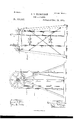
In the accompanying drawings, Figure 1, Sheet 1, is a side view of sufficient of a hodelevator to illustrate my improvements; Fig.
-2, Sheet 2, a side view, partly in section, of
the upper portion of the same on a larger scale; Fig. 3, an end view, partly in section, and looking in thedirection of the arrow, Fig. 2; Fig. 4, Sheet 1, a view of the drivingshaft; andFig. 5, a view illustrating a modification of one of the features of my invention.
The elevator structure comprises the lower frame, A, upper frame, B, endless chains D D, lower chain-wheels, F, and upper chain-wheels, G, the lower frame, A, which carries the shaft a of the wheels F, being generally placed on the first floor, or in the basement of the building, and the upper frame, B, which carries the shaft 12 of the wheels G, being raised from floor to floor as the building of the walls progresses, the chains being lengthened as required at each change of location of the upper frame. Usually the upper frame comprises opposite sides and transverse braces, the whole being fitted together and rigidly secured, so as to form a structure which has to be moved bodily from one position to another. In consequence of this, openings large enough for the passage of the frame B must be left in each floor of the building until the walls are completed and the said frame is taken down. This is an objection which I overcome by making the upper frame, B, in such manner that it can be readily taken apart, carried to an upper floor, and thereput together again, so that it is only necessary to leave in the floors openings large enough for the passage of the elevator-chains and hods, these openings being of limited area-for instance, such as may be formed by leaving out one of the joists, x, of the flooring, as shown in Fig. 3.
Each of the opposite sides of the frame comprises a base-bar, d, a central vertical post, 6, and opposite braces f f, the whole being securely bolted together and forming a self-contained structure, which, however, being fiat, can be readily hoisted between the floor-j oists. These side frames are kept at the proper distance apart by suitable transverse bars, 9, at the bottom and by the shaft 1) at the top. The wheels G have outer flanges, and are held at the proper distance apart on the shaft by the chains D D, the latter being properly spaced by the cross-bars h, carrying the trestles t, on which the hods are deposited, as shown in Fig. 1, undue separation of the wheels G being prevented by collars j, bolted to the shaft b, as shown in Fig. 3. These collars have squared proj ectionsj, adapted to recesses e in the tops of the posts 6, and are provided with flanges.
j against which the upper ends of the posts 6 have a bearing. The opposite sides of the frame B being thus properly held apart at top and bottom, it only remains to provide bolts m for tying the posts 6 transversely together in order to complete the frame. These bolts are preferably arranged diagonally, as shown, so as to afford facilities for the lateral adjustment of the upper ends of the side frames in order to insure the proper leveling of the shaft 2) and the centering of the wheels G above the openings in the floors without blocking up the frames, the proper adjustment of the upper ends of the side frames being effected by simply loosening one bolt on and tightening the other, as may be necessary.
The shaft a of the lower chain-wheels, F, is driven by spur-gearing from a driving-shaft, J, which, as shown in Fig. 4, has opposite crank-handlespp and afly-wheel, J, the crankhandle 19 in the present instance being attached to one of the spokes of the fly-wheel. In the absence of this fly-wheel on a hand-elevator of the class to which my invention relates, the throwing of the loaded hods onto the ascending trestles causes such sudden and severe strains on the gearing that the labor of operating the elevator is very severe upon the men, who have to be frequently relieved. By the use of a fly-wheel, however, I oppose the momentum of the latter to the strains caused by depositing the loaded hods upon the trestles, and hence obviate these shocks upon the driving-shaft, the movement of which is uniform, and is imparted thereto by the men at the cranks with out undue fatigue. Unless the loaded hod is removed from the trestles 1; as it reaches the upper end of the elevator, it will be thrown from the trestles and. overturned as said trestles pass over the wheels G. To prevent this accident, I hang to the posts 6 of the upper frame, B, a pair of arms, 8 s, the outer ends of which are connected by a transverse rod, 3. One of these arms has a trigger, s, which engages with one arm of a catch-lever, t, hung to the post 6, the other arm of which is connected, by means of rods '1) o and. a lever, c, to a weighted brake-lever, K, hung to the base of the frame A, and having a shoe adapt ed to bear upon the periphery of the fly-Wheel J As long as the lever t is retained by the trigger the weighted arm of the brake-1ever K is elevated and the shoe is free from contact with the flywheel; but as soon as the rod 8 is struck by an ascending hod or its load the lever t is released, and the weight on the lever K causes the instant application of the brake and the stoppage of the driving-shaft. The resetting of the parts is effected by means of a rod or cord, t, connected to the lever 15, and extending to a point within convenient reach of the men who are operating the elevator.
Although I prefer this trigger arrangement for applying the brake, the use of the same is not essential. For instance, one of the arms 8 may be directly connected to a brake-lever, as shown in Fig. 5, the application of the brake being effected by the elevation of the arms, or one only of the latter may be used, providing it has a projection to be struck by the ascending hod.
I claim as my invention- 1. The combination of the chain and chainpulleys of the hoist,with the upper frame, B, comprising the independent side frames, the spacing-beams, the shaft 1), and the tie-bolts, as set forth. 7
2. The combination of the chains and chainpulleys of the hoist, with the upper frame comprising the independent side frames, spacingbeams, shaft b, and tie-bolts, the latter being arranged diagonally, as set forth.
3. The combination of the chains D and flanged chain-pulleys G, with the shaft I), having collars j with projections j, and the opposite side frames having recesses e, for the reception of the said projections, as set forth.
4. The combination of the frames, chains, and chain-pulleys of a hod-elevatoixwith the driving-shaft J having a crank handle or handles and a fly-wheel, J as set forth.
5. The combination of the pulleys. chains, and driving mechanism of a hod-elevator,with a brake-lever, a stop-arm having a portion projecting into the path of the ascending hods, and connecting devices, substantially as described, whereby the undue ascent of a hod is caused to effect the application of the brake, as set forth.
6. The combination of the chains, chainwheels, and operating mechanism, the weight ed brake-lever K, the catch-lever t, connected thereto, and a trigger-arm, s, as set forth.
In testimony whereof I have signed my name to this specification in the presence of two subscribing witnesses.
COLEMAN L. NICHOLSON.
XVitnesses:
J OHN E. PARKER, HARRY SMITH.
Publications (1)
| Publication Number | Publication Date |
|---|---|
| US290347A true US290347A (en) | 1883-12-18 |
Family
ID=2359535
Family Applications (1)
| Application Number | Title | Priority Date | Filing Date |
|---|---|---|---|
| US290347D Expired - Lifetime US290347A (en) | Hod-elevator |
Country Status (1)
| Country | Link |
|---|---|
| US (1) | US290347A (en) |
-
0
- US US290347D patent/US290347A/en not_active Expired - Lifetime
Similar Documents
| Publication | Publication Date | Title |
|---|---|---|
| US375293A (en) | Passenger-elevator | |
| US412956A (en) | Elevator | |
| US495185A (en) | Mechanical toy | |
| US263570A (en) | Elevator for building material | |
| US144161A (en) | Improvement in elevators | |
| US130824A (en) | Improvement in elevators | |
| US1173866A (en) | Automatic sheep-dipping apparatus. | |
| US276785A (en) | Elevator | |
| US547105A (en) | Adjustable hod-elevator | |
| US52811A (en) | Improved device for driving fence-posts | |
| US228591A (en) | Portable elevator | |
| US321348A (en) | Lumber-filer | |
| US288073A (en) | Elevating | |
| US240227A (en) | George w | |
| US286119A (en) | Hod-elevator | |
| US273048A (en) | ferguson | |
| US118783A (en) | Improvement in brick and mortar-elevators | |
| US141297A (en) | Improvement in hoisting and conveying apparatus | |
| US741026A (en) | Stump-extractor. | |
| US747133A (en) | Elevating baggage-truck. | |
| US420677A (en) | Hoisting-machine | |
| US121436A (en) | Improvement in stump-extractors | |
| US156834A (en) | Improvement in water drawers or elevators | |
| US265923A (en) | Water-elevator | |
| US435738A (en) | Lumber-filer |