US2901111A - Vibrator chute - Google Patents
Vibrator chute Download PDFInfo
- Publication number
- US2901111A US2901111A US672223A US67222357A US2901111A US 2901111 A US2901111 A US 2901111A US 672223 A US672223 A US 672223A US 67222357 A US67222357 A US 67222357A US 2901111 A US2901111 A US 2901111A
- Authority
- US
- United States
- Prior art keywords
- chutes
- chute
- hangers
- vibrator
- eccentric
- Prior art date
- Legal status (The legal status is an assumption and is not a legal conclusion. Google has not performed a legal analysis and makes no representation as to the accuracy of the status listed.)
- Expired - Lifetime
Links
Images
Classifications
-
- B—PERFORMING OPERATIONS; TRANSPORTING
- B65—CONVEYING; PACKING; STORING; HANDLING THIN OR FILAMENTARY MATERIAL
- B65G—TRANSPORT OR STORAGE DEVICES, e.g. CONVEYORS FOR LOADING OR TIPPING, SHOP CONVEYOR SYSTEMS OR PNEUMATIC TUBE CONVEYORS
- B65G27/00—Jigging conveyors
- B65G27/10—Applications of devices for generating or transmitting jigging movements
- B65G27/28—Applications of devices for generating or transmitting jigging movements with provision for dynamic balancing
- B65G27/30—Applications of devices for generating or transmitting jigging movements with provision for dynamic balancing by means of an oppositely-moving mass, e.g. a second conveyor
Definitions
- Coupled, counterrunning vibrator chutes such as delivery or conveyer troughs, riddles or vibrating screens are much used, for example in transport means, machines for cleaning or scouring semolina, farina or middlings, grain separators and the like. They are particularly suited for use in the air-compensation in closed boxes.
- My present invention discloses an advantageous construction of such shaking or vibrating chutes, in which the conditions of acceleration and deceleration are substantially improved by virtue of the introduction of frictional forces in the suspension gear.
- the present invention relates to a conveying or delivery apparatus comprising two coupled reciprocable shaking chutes such as delivery troughs, riddles or the like.
- Said apparatus as known per se, comprises a drive shaft journaled on one of said chutes and provided with an eccentric which through a coupling rod is pivotally connected to the other chute.
- said known apparatus is characterized in that one of the two chutes is suspended by hangers, its position of rest being determined by springs engaging said hangers, and the other chute is supported by slide shoes or slippers.
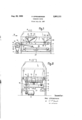
- FIG. 1 is a side view of the machine
- Fig. 2 is a front elevation of the machine in a larger scale and in direction of the arrow B in Fig. 1.
- a first vibrator chute 2 formed as sieve carrier is suspended by hangers 3.
- a second vibrator chute 5, formed as delivery trough, is carried through slide shoes 6 on corresponding counterface-brackets 7 secured to frame 1.
- the products of the grinding operation are poured on the sieves of carrier 2.
- the material passing through the sieves falls into delivery trough 5.
- a suction channel 8 draws air through sieve carrier 2 to remove the bran particles.
- To sieve carrier 2 are fixed two brackets 10 in which a drive shaft 11 provided with an eccentric 12 is journaled. The latter is pivotally connected to trough 5 2,901,111 ?atented Aug. 25, 1959 the through a coupling rod 13. To drive shaft 11 is fixed at each end a pulley 14 and 15 respectively, of which pulley 14 is driven through a motor 17. As the traction of belt 16 is generally at right angles to the direction of vibration, the shaking movement is not disturbed. To compensate the unbalance of eccentric 12, counterpoises 19 are fixed to the two pulleys 14 and 115.
- the position of rest of sieve carrier 2 is determined by springs 22 which engage the hangers 3.
- a turnbuckle 23 allows of adjusting the length of the hangers 3.
- Another turnbuckle 24 allows of adjusting the spring tension.
- a set screw 25 allows of changing the point of attack of the springs 22 on the hangers 3.
- the stroke of sieve carrier '2 and of delivery trough 5 depends on the eccentricity of eccentric 12 with respect to shaft 11 and on the ratio of the masses of sieve carrier 2 and trough 5.
- a variable weight 27 allows of changing said ratio. In lieu of weight 27, variable weights may be attached to sieve carrier 2.
- Chute 5 is provided with an inclined bottom 28.
- Such inclined bottoms are known per se and may be made of one slope throughout or of subdivided slope or foldable or reversible.
- a conveyer in combination: a pair of reciprocable vibrator chutes, a drive shaft connected with one of said chutes, an eccentric on said shaft, a coupling rod having one end pivotally connected to the other of said chutes and another end operatively connected with said eccentric, a plurality of hangers for suspending one of said chutes, spring means connected with said hangers for determining the position of rest of said last mentioned chute, and slide shoes for carrying the other of said chutes.
- variable weight means connected with one of said chutes for changing the ratio of masses of said chutes.
Landscapes
- Engineering & Computer Science (AREA)
- Mechanical Engineering (AREA)
- Combined Means For Separation Of Solids (AREA)
Description
g- 25, 1959 P. EPPENBERGER 2,901,111
' VIBRATOR CHUTE 1 I Filed July 16, 1957 8 Fig.1
lnvenkor:
nite Sta VIBRATOR CHUTE Paul Eppenherger, Amriswil, Switzerland, assignor t Geln'ueder Buehler, Uzwil, Switzerland, a Swiss firm Application July 16, 1957, Serial No. 672,223 Claims priority, application Switzerland July 24, 1956 3 Claims. (Cl. 209-344) Coupled, counterrunning vibrator chutes such as delivery or conveyer troughs, riddles or vibrating screens are much used, for example in transport means, machines for cleaning or scouring semolina, farina or middlings, grain separators and the like. They are particularly suited for use in the air-compensation in closed boxes.
My present invention discloses an advantageous construction of such shaking or vibrating chutes, in which the conditions of acceleration and deceleration are substantially improved by virtue of the introduction of frictional forces in the suspension gear.
The present invention relates to a conveying or delivery apparatus comprising two coupled reciprocable shaking chutes such as delivery troughs, riddles or the like. Said apparatus, as known per se, comprises a drive shaft journaled on one of said chutes and provided with an eccentric which through a coupling rod is pivotally connected to the other chute. As disclosed by the present invention, said known apparatus is characterized in that one of the two chutes is suspended by hangers, its position of rest being determined by springs engaging said hangers, and the other chute is supported by slide shoes or slippers.
One form of the invention is schematically shown, by way of example and as applied to a machine for cleaning or scouring semolina, farina or middlings. In the drawing, Fig. 1 is a side view of the machine, and Fig. 2 is a front elevation of the machine in a larger scale and in direction of the arrow B in Fig. 1.
From the machine frame 1 a first vibrator chute 2 formed as sieve carrier is suspended by hangers 3. A second vibrator chute 5, formed as delivery trough, is carried through slide shoes 6 on corresponding counterface-brackets 7 secured to frame 1.
As generally known, the products of the grinding operation are poured on the sieves of carrier 2. The material passing through the sieves falls into delivery trough 5. A suction channel 8 draws air through sieve carrier 2 to remove the bran particles.
To sieve carrier 2 are fixed two brackets 10 in which a drive shaft 11 provided with an eccentric 12 is journaled. The latter is pivotally connected to trough 5 2,901,111 ?atented Aug. 25, 1959 the through a coupling rod 13. To drive shaft 11 is fixed at each end a pulley 14 and 15 respectively, of which pulley 14 is driven through a motor 17. As the traction of belt 16 is generally at right angles to the direction of vibration, the shaking movement is not disturbed. To compensate the unbalance of eccentric 12, counterpoises 19 are fixed to the two pulleys 14 and 115.
The position of rest of sieve carrier 2 is determined by springs 22 which engage the hangers 3. A turnbuckle 23 allows of adjusting the length of the hangers 3. Another turnbuckle 24 allows of adjusting the spring tension. A set screw 25 allows of changing the point of attack of the springs 22 on the hangers 3. By these means it is possible, for example, to vary the inclination of the hangers 3 in the position of rest of carrier 2 and, thereby, to regulate the angle of throw of the sieves of carrier 2. When making the hangers 3 of different lengths sieve carrier 2 may be made sloping, which may be desirable in certain applications.
The stroke of sieve carrier '2 and of delivery trough 5 depends on the eccentricity of eccentric 12 with respect to shaft 11 and on the ratio of the masses of sieve carrier 2 and trough 5. A variable weight 27 allows of changing said ratio. In lieu of weight 27, variable weights may be attached to sieve carrier 2.
Chute 5 is provided with an inclined bottom 28. When the inclination is in the other direction, the direction of delivery or feed is changed. Such inclined bottoms are known per se and may be made of one slope throughout or of subdivided slope or foldable or reversible.
What I claim as new and desire to secure by Letters Patent, is: 1 j
1. In a conveyer, in combination: a pair of reciprocable vibrator chutes, a drive shaft connected with one of said chutes, an eccentric on said shaft, a coupling rod having one end pivotally connected to the other of said chutes and another end operatively connected with said eccentric, a plurality of hangers for suspending one of said chutes, spring means connected with said hangers for determining the position of rest of said last mentioned chute, and slide shoes for carrying the other of said chutes.
2. The structure as set forth in claim 1, further comprising variable weight means connected with one of said chutes for changing the ratio of masses of said chutes.
3. The structure as set forth in claim 1, further comprising at least one counterpoise attached to said shaft for compensating the unbalance of said eccentric.
References Cited in the file of this patent UNITED STATES PATENTS 672,420 Le Grand Apr. 16, 1901 2,154,060 Bergmann Apr. 11, 1909 2,332,600 Rapp Oct. 26, 1943 2,563,081 Tanner Aug. 7, 1951
Applications Claiming Priority (1)
| Application Number | Priority Date | Filing Date | Title |
|---|---|---|---|
| CH2901111X | 1956-07-24 |
Publications (1)
| Publication Number | Publication Date |
|---|---|
| US2901111A true US2901111A (en) | 1959-08-25 |
Family
ID=4572646
Family Applications (1)
| Application Number | Title | Priority Date | Filing Date |
|---|---|---|---|
| US672223A Expired - Lifetime US2901111A (en) | 1956-07-24 | 1957-07-16 | Vibrator chute |
Country Status (1)
| Country | Link |
|---|---|
| US (1) | US2901111A (en) |
Cited By (5)
| Publication number | Priority date | Publication date | Assignee | Title |
|---|---|---|---|---|
| US3351201A (en) * | 1961-05-24 | 1967-11-07 | Buehler Ag Geb | Oscillating screen with hanger supports |
| US4021337A (en) * | 1974-09-11 | 1977-05-03 | Klockner-Humboldt-Deutz Aktiengesellschaft | Sieve with drive |
| US4287779A (en) * | 1979-07-05 | 1981-09-08 | Goncharov Evgeny S | Directional-action mechanical vibrator and a mechanical system for converting rotary motion into reciprocating motion |
| US4351719A (en) * | 1981-02-19 | 1982-09-28 | Morbark Industries, Inc. | Vibrating screen apparatus |
| US20110072917A1 (en) * | 2008-06-30 | 2011-03-31 | Metso Minerals Inc. | Vibrating aggregate, an apparatus for processing mineral material, and a method for moving a processing device of an apparatus for processing mineral material |
Citations (4)
| Publication number | Priority date | Publication date | Assignee | Title |
|---|---|---|---|---|
| US672420A (en) * | 1900-05-10 | 1901-04-16 | John N Thomas | Stroke-cushion attachment for shaking-screens. |
| US2154060A (en) * | 1936-06-19 | 1939-04-11 | Goodman Mfg Co | Feeding mechanism for shaker or jigging conveyers |
| US2332600A (en) * | 1941-09-08 | 1943-10-26 | L R Muskat | Vibrating conveyer trough |
| US2563081A (en) * | 1947-08-28 | 1951-08-07 | Buehler Ag Geb | Sieve carrier adjustably suspended from machine frame and actuated by a free-swing drive |
-
1957
- 1957-07-16 US US672223A patent/US2901111A/en not_active Expired - Lifetime
Patent Citations (4)
| Publication number | Priority date | Publication date | Assignee | Title |
|---|---|---|---|---|
| US672420A (en) * | 1900-05-10 | 1901-04-16 | John N Thomas | Stroke-cushion attachment for shaking-screens. |
| US2154060A (en) * | 1936-06-19 | 1939-04-11 | Goodman Mfg Co | Feeding mechanism for shaker or jigging conveyers |
| US2332600A (en) * | 1941-09-08 | 1943-10-26 | L R Muskat | Vibrating conveyer trough |
| US2563081A (en) * | 1947-08-28 | 1951-08-07 | Buehler Ag Geb | Sieve carrier adjustably suspended from machine frame and actuated by a free-swing drive |
Cited By (6)
| Publication number | Priority date | Publication date | Assignee | Title |
|---|---|---|---|---|
| US3351201A (en) * | 1961-05-24 | 1967-11-07 | Buehler Ag Geb | Oscillating screen with hanger supports |
| US4021337A (en) * | 1974-09-11 | 1977-05-03 | Klockner-Humboldt-Deutz Aktiengesellschaft | Sieve with drive |
| US4287779A (en) * | 1979-07-05 | 1981-09-08 | Goncharov Evgeny S | Directional-action mechanical vibrator and a mechanical system for converting rotary motion into reciprocating motion |
| US4351719A (en) * | 1981-02-19 | 1982-09-28 | Morbark Industries, Inc. | Vibrating screen apparatus |
| US20110072917A1 (en) * | 2008-06-30 | 2011-03-31 | Metso Minerals Inc. | Vibrating aggregate, an apparatus for processing mineral material, and a method for moving a processing device of an apparatus for processing mineral material |
| US9339847B2 (en) * | 2008-06-30 | 2016-05-17 | Metso Minerals Inc. | Vibrating aggregate, an apparatus for processing mineral material, and a method for moving a processing device of an apparatus for processing mineral material |
Similar Documents
| Publication | Publication Date | Title |
|---|---|---|
| US3227263A (en) | Vibratory regulation of an endless conveying device | |
| CN1313040C (en) | Belt conveyors for transporting tobacco material | |
| US2901111A (en) | Vibrator chute | |
| US2669344A (en) | Balanced sectionalized vibratory conveyer | |
| US2164796A (en) | Method and apparatus for feeding coal | |
| US2725984A (en) | Vibratory conveyors | |
| US2245650A (en) | Grain separating machine | |
| GB857250A (en) | Oscillating machine | |
| RU2051757C1 (en) | Separator | |
| RU2306985C2 (en) | Garbage sorting out apparatus | |
| US3122930A (en) | Vibrating mechanism and unbalancing rotor | |
| US2730237A (en) | Vibrating screens | |
| US1993615A (en) | Mounting of oscillating apparatus | |
| US3027101A (en) | Milling apparatus | |
| US639710A (en) | Screening and assorting apparatus for coal, &c. | |
| US2355131A (en) | Grading machine | |
| SU1488028A1 (en) | Separator for primary cleaning of grain | |
| US460436A (en) | Grain and cockle separator | |
| Fouda | Engineering studies on the performance of paddy and rice separator | |
| US392713A (en) | Fanning-mill | |
| US707701A (en) | Separator. | |
| US3236380A (en) | Material classifying apparatus | |
| US111541A (en) | Improvement in shoes for thrashers | |
| US3029924A (en) | Vibrating feeder | |
| US734761A (en) | Grain separator and grader. |