US2894641A - Storage rack - Google Patents
Storage rack Download PDFInfo
- Publication number
- US2894641A US2894641A US678632A US67863257A US2894641A US 2894641 A US2894641 A US 2894641A US 678632 A US678632 A US 678632A US 67863257 A US67863257 A US 67863257A US 2894641 A US2894641 A US 2894641A
- Authority
- US
- United States
- Prior art keywords
- channel
- openings
- brackets
- webs
- rails
- Prior art date
- Legal status (The legal status is an assumption and is not a legal conclusion. Google has not performed a legal analysis and makes no representation as to the accuracy of the status listed.)
- Expired - Lifetime
Links
Images


Classifications
-
- B—PERFORMING OPERATIONS; TRANSPORTING
- B65—CONVEYING; PACKING; STORING; HANDLING THIN OR FILAMENTARY MATERIAL
- B65G—TRANSPORT OR STORAGE DEVICES, e.g. CONVEYORS FOR LOADING OR TIPPING, SHOP CONVEYOR SYSTEMS OR PNEUMATIC TUBE CONVEYORS
- B65G1/00—Storing articles, individually or in orderly arrangement, in warehouses or magazines
- B65G1/02—Storage devices
-
- A—HUMAN NECESSITIES
- A47—FURNITURE; DOMESTIC ARTICLES OR APPLIANCES; COFFEE MILLS; SPICE MILLS; SUCTION CLEANERS IN GENERAL
- A47B—TABLES; DESKS; OFFICE FURNITURE; CABINETS; DRAWERS; GENERAL DETAILS OF FURNITURE
- A47B47/00—Cabinets, racks or shelf units, characterised by features related to dismountability or building-up from elements
- A47B47/02—Cabinets, racks or shelf units, characterised by features related to dismountability or building-up from elements made of metal only
- A47B47/021—Racks or shelf units
- A47B47/022—Racks or shelf units with cantilever shelves
-
- A—HUMAN NECESSITIES
- A47—FURNITURE; DOMESTIC ARTICLES OR APPLIANCES; COFFEE MILLS; SPICE MILLS; SUCTION CLEANERS IN GENERAL
- A47B—TABLES; DESKS; OFFICE FURNITURE; CABINETS; DRAWERS; GENERAL DETAILS OF FURNITURE
- A47B47/00—Cabinets, racks or shelf units, characterised by features related to dismountability or building-up from elements
- A47B47/02—Cabinets, racks or shelf units, characterised by features related to dismountability or building-up from elements made of metal only
- A47B47/021—Racks or shelf units
- A47B47/027—Racks or shelf units with frames only
Definitions
- One of the objects of the invention is to provide a system of frames including horizontal elements and vertical supports which lend themselves to embodiment in various ventilation and inspection arrangements to provide storage racks for drying tobacco; storage of barrels or hogsheads; or where space is a problem in storing other merchandise, to be so assembled as to effect more closely spaced frames to meet the demands of a larger volume of storage space.
- Another object of the invention is to provide a storage rack including frames spaced to provide unobstructed aisleways for admitting a lift truck and permitting storage of articles to be supported and freely removed without hindrance from the framework.
- Each of the frames comprises elements forming load carrying columns intended to support horizontally disposed rails projecting inwardly from opposite columns thereby to provide footings, at selected elevations for pallets, hogsheads, crates, boxes or the like, and which in all of these adaptations, provides an unrestricted aisleway for truck entry from one or both ends depending on whether or not one end faces a wall or stands in the clear like the other.
- a further object of the invention is to provide a rack of great flexibility in use and which includes structural shapes which readily lend themselves to simple manufacturing procedures, and which may be assembled from stock to provide aisleways of any desired width.
- Fig. 1 is a perspective view of a rack including frames spaced to provide merchandise storage aisleways and inspection corridors.
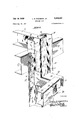
- Fig. 2 is an enlarged detail perspective view of the structural elements providing the load carrying columns, horizontal braces, rail supporting brackets and rails.
- Fig; 3 is a detail elevation of one of the columns and associated elements shown in Figs. 1 and 2.
- Fig. 4 is a detail front elevation of a frame omitting the spacing elements forming the inspection corridors.
- Fig. 5 is a detail side elevation of the arrangement shown in Fig. 4.
- Fig. 6 is a detail cross-section taken on the line 66 of Fig. 4.
- the invention includes in its organization upright supports or columns A and laterally offset but longitudinally disposed rails B, said rails projecting toward each other from opposite frames, and the supports being connected by the horizontal braces C.
- the elements are assembled in at least a pair of cooperatively related frames designated generally as D and spaced to provide an aisleway E therebetween.
- the columns A are of special formation in the respect that their cross sectional shape is such as to provide a medial channel and socket forming portion A (Fig. 2) flanked on either side by reversely related fastening receiving channel portions A
- the medial channel portion A includes a bottom Wall or web 1, and sidewalls 22 connected with the bottom walls or webs 3-3 of the outer fastening receiving channel portions A the latter having the outer walls 4-4.
- the outer side of the web of the medial channel faces the aisleway E.
- the webs 33 of the outer channel portions A are provided with a plurality of vertically spaced openings 5, which, as will presently appear, are intended to receive fastenings 6.
- the walls 2-2 of the channel A, in conjunction with the web 1 provide, in effect, at their outer side, a continuous vertical socket portion 1* for receiving an end of spacer members 7 when the supports A are to be spaced apart as shown in Figs. 1 and 2 thereby to provide air circulating space, as well as an inspection corridor F where a man can enter, as for example in the event that the structure is used for tobacco drying, or storing hogsheads or other merchandise where free air circulation and inspection are required.
- the supports A are held together by the aforesaid horizontally disposed braces C to form the frames by the said fastenings 6 connecting the channel shaped braces with the columns.
- the horizontally and longitudinally disposed braces C are not at the same elevation as the members 7 for spacing the upright columns so that the opposite ends of the latter will readily fit in the sockets 1 of the medial channel portion of each pair of upright columns A to hold them in position to provide the ventilation or inspection corridor previously referred to.
- the spaced members 7 have their opposite end portions welded in the walls 2-2 of the socket channel.
- the brackets 5 include a horizontal web portion 10 and rearwardly extending downturned flanges 11 whose inner ends straddle the channel A and terminate in the angular attaching feet 12 disposed in the related valley of the outer fastening receiving channel portions A These feet are provided with openings for registry with the openings 5 so that the fastenings 6 will connect the feet 12 with the uprights while at the same time connecting the longitudinal channel braces C with the uprights.
- the outer portionsof the flanges of the brackets 9 are also provided with openings to receive the fastenings 13 which connect the angularly disposed ears 14 of adjacent sections 15 of the rail B with the outer ends of the brackets.
- the rails B are made of sections of transversely U- shaped or channel formation and near the ends thereof as will be apparent from Fig. 2 the aforesaid ears 14 are punched inwardly from the Web of the channel and are provided with holes to receive the fastenings 13 to rigidly secure the rails to the appropriate bracket 9.
- the length of the brackets 9, that is, the distance which the web 10 and flanges 11 project outwardly of the vertical supports A may be lengthened as desired to provide adequate bearing support for some types of containers in the aisleway between the frames D. For example, as some barrels that have end portions needing more support at each end than others.
- the upright supports A are assembled in spaced corridors forming relation by the spacing members 7 and the lower ends of the up- J) rights A A rest upon and are Welded to suitable base plates 16 anchored to the floor.
- the lower portion of the uprights may be provided with a strip 17 which acts as a rub-rail or scuff strip and tends to aid in keeping pallets P or the like, properly alined Within the bottom of the aisleway E formed between the opposite frames D.
- the rub-rails are preferably constructed of angle shaped members 17 with a top flange 19 Which is notched out as at 20 to fit flat against one side of the uprights.
- the ends of the vertical flange portions are provided with openings which cooperate with similar openings in the medial channel A to receive suitable fastenings 21.
- the vertical supports A of the frames may have the bottom portions or webs 3 of their outer fastening receiving channels disposed in abutting relation as shown in Figs. 4, 5 and 6, which, of course, means that the spacing members 7 are omitted.
- the openings 5 in the webs 3 of the outer fastening channels A may receive bolts for securing mating upright columns in abutting relation, and, of course, it will be understood that the columns are held in desired longitudinal spaced relation by the longitudinal braces C. Also, it will be understood that the said columns A in this arrangement support the brackets 9 to secure the sections of the rails B in place.
- the uprights A are preferably secured together at their top edges by the connecting strips 18, and likewise the bottom or foot portions of the vertical members may be secured to the floor by suitable plates.
- each of said frame elements including, upright supports spaced longitudinally of said frame elements and each of a cross-sectional shape to provide a medial channel having a bottom Wall facing said aisleway, inner side walls connected with said bottom wall and projecting at right angles thereto, webs connected at right angles to said inner side walls and provided with vertically spaced openings, an outer wall depending from each of said webs, said inner side walls, webs and outer walls forming fastening receiving channel portions reversely disposed to said medial channel, charmel shaped braces disposed transversely of the upright supports and having openings registering with said openings in the webs of the uprights to receive fasten ings therethrough to rigidly secure the braces to said upright supports, channel shaped brackets each comprising a horizontal web portion, vertical side flanges depending from said Web portion and extending beyond one edge thereof to embrace said medial channel of the
- a pair of skeleton frame elements laterally spaced apart from each other and cooperating to provide an open ended aisleway therebetween, each of said frame elements including a series of upright supports spaced longitudinally of said frame elements and of a cross-sectional shape to provide a medial channel having a bottom wall Whose outer face is disposed toward said aisleway, and whose side walls connect with said bottom wall and project at right angles thereto, webs connected to the terminal portions of said side walls and disposed at right angles thereto, inverted channel shaped brackets each comprising a horizontal web portion and vertical depending side flanges having portions adjacent the side walls of the upright to embrace the same, and foot portions disposed at right angles to said depending side walls and secured to the webs of the uprights, and load carrying channel shaped supporting rails telescopically fitting over the aisle end of the bracket and rigidly secured thereto.
- a merchandise storage rack assembly comprising, a pair of skeleton frame elements laterally spaced apart to cooperate in providing open ended storage aisle- Ways therebetween which permit unobstructed entry and exit of fork lift trucks or like materials handling equipment, said frame elements including upright supports of a cross-sectional shape to provide a medial channel having a bottom wall facing said storage aisleways, inner side walls connected with said bottom wall and projecting at right angles thereto, webs connected at right angles to said inner side walls and provided with vertically spaced openings, an outer wall depending from each of said webs, said inner side walls, webs and outer walls forming fastening receiving channel portions reversely disposed to said medial channel, channel shaped braces disposed transversely of the upright supports and having openings registering with said openings in the Webs of the uprights to receive fastenings therethrough to rigidly secure the braces to said upright supports, channel shaped brackets each comprising a horizontal web portion, vertical side flanges depending from said web portion and extending beyond one edge thereof to embrace said medial
Landscapes
- Engineering & Computer Science (AREA)
- Mechanical Engineering (AREA)
- Assembled Shelves (AREA)
Description
uly 14, 1959 L. B. EDWAR-DS, JR 2,894,641
STORAGE RACK Filed Aug. 16. 1957 3 Sheets-Sheet 1 F INVENT OR a ORNEY B. EDWARDS, JR
Filed Aug. 16, 1957 July 14, 1959 w /0 v vw United States Patent STORAGE RACK Landon B. Edwards, Jr., Richmond, Va.
Application August 16, 1957, Serial No. 678,632 3 Claims. or. 211-134 ,This invention relates to racks for storing merchandise.
One of the objects of the invention is to provide a system of frames including horizontal elements and vertical supports which lend themselves to embodiment in various ventilation and inspection arrangements to provide storage racks for drying tobacco; storage of barrels or hogsheads; or where space is a problem in storing other merchandise, to be so assembled as to effect more closely spaced frames to meet the demands of a larger volume of storage space.
Another object of the invention is to provide a storage rack including frames spaced to provide unobstructed aisleways for admitting a lift truck and permitting storage of articles to be supported and freely removed without hindrance from the framework. Each of the frames comprises elements forming load carrying columns intended to support horizontally disposed rails projecting inwardly from opposite columns thereby to provide footings, at selected elevations for pallets, hogsheads, crates, boxes or the like, and which in all of these adaptations, provides an unrestricted aisleway for truck entry from one or both ends depending on whether or not one end faces a wall or stands in the clear like the other.
A further object of the invention is to provide a rack of great flexibility in use and which includes structural shapes which readily lend themselves to simple manufacturing procedures, and which may be assembled from stock to provide aisleways of any desired width.
With the above and other objects in view which will more readily appear as the nature of the invention is better understood, the same consists in the novel construction, combination, and arrangement of parts hereinafter more fully described, illustrated and claimed.
A preferred and practical embodiment of the invention is shown in the accompanying drawings, in which:
Fig. 1 is a perspective view of a rack including frames spaced to provide merchandise storage aisleways and inspection corridors.
Fig. 2 is an enlarged detail perspective view of the structural elements providing the load carrying columns, horizontal braces, rail supporting brackets and rails.
Fig; 3 is a detail elevation of one of the columns and associated elements shown in Figs. 1 and 2.
Fig. 4 is a detail front elevation of a frame omitting the spacing elements forming the inspection corridors.
Fig. 5 is a detail side elevation of the arrangement shown in Fig. 4.
Fig. 6 is a detail cross-section taken on the line 66 of Fig. 4.
Similar reference characters designate corresponding parts throughout the several figures of the drawing.
Referring to Fig. 1, it will be observed that the invention includes in its organization upright supports or columns A and laterally offset but longitudinally disposed rails B, said rails projecting toward each other from opposite frames, and the supports being connected by the horizontal braces C. The elements are assembled in at least a pair of cooperatively related frames designated generally as D and spaced to provide an aisleway E therebetween.
The columns A are of special formation in the respect that their cross sectional shape is such as to provide a medial channel and socket forming portion A (Fig. 2) flanked on either side by reversely related fastening receiving channel portions A The medial channel portion A includes a bottom Wall or web 1, and sidewalls 22 connected with the bottom walls or webs 3-3 of the outer fastening receiving channel portions A the latter having the outer walls 4-4. The outer side of the web of the medial channel faces the aisleway E.
The webs 33 of the outer channel portions A are provided with a plurality of vertically spaced openings 5, which, as will presently appear, are intended to receive fastenings 6.
The walls 2-2 of the channel A, in conjunction with the web 1 provide, in effect, at their outer side, a continuous vertical socket portion 1* for receiving an end of spacer members 7 when the supports A are to be spaced apart as shown in Figs. 1 and 2 thereby to provide air circulating space, as well as an inspection corridor F where a man can enter, as for example in the event that the structure is used for tobacco drying, or storing hogsheads or other merchandise where free air circulation and inspection are required.
The supports A are held together by the aforesaid horizontally disposed braces C to form the frames by the said fastenings 6 connecting the channel shaped braces with the columns. It will, of course, be seen that the horizontally and longitudinally disposed braces C are not at the same elevation as the members 7 for spacing the upright columns so that the opposite ends of the latter will readily fit in the sockets 1 of the medial channel portion of each pair of upright columns A to hold them in position to provide the ventilation or inspection corridor previously referred to. The spaced members 7 have their opposite end portions welded in the walls 2-2 of the socket channel.
As will be seen more in detail from Fig. 2 the brackets 5 include a horizontal web portion 10 and rearwardly extending downturned flanges 11 whose inner ends straddle the channel A and terminate in the angular attaching feet 12 disposed in the related valley of the outer fastening receiving channel portions A These feet are provided with openings for registry with the openings 5 so that the fastenings 6 will connect the feet 12 with the uprights while at the same time connecting the longitudinal channel braces C with the uprights.
The outer portionsof the flanges of the brackets 9 are also provided with openings to receive the fastenings 13 which connect the angularly disposed ears 14 of adjacent sections 15 of the rail B with the outer ends of the brackets.
The rails B are made of sections of transversely U- shaped or channel formation and near the ends thereof as will be apparent from Fig. 2 the aforesaid ears 14 are punched inwardly from the Web of the channel and are provided with holes to receive the fastenings 13 to rigidly secure the rails to the appropriate bracket 9. The length of the brackets 9, that is, the distance which the web 10 and flanges 11 project outwardly of the vertical supports A may be lengthened as desired to provide adequate bearing support for some types of containers in the aisleway between the frames D. For example, as some barrels that have end portions needing more support at each end than others.
As shown in Figs. 1 and 2 the upright supports A are assembled in spaced corridors forming relation by the spacing members 7 and the lower ends of the up- J) rights A A rest upon and are Welded to suitable base plates 16 anchored to the floor. The lower portion of the uprights may be provided with a strip 17 which acts as a rub-rail or scuff strip and tends to aid in keeping pallets P or the like, properly alined Within the bottom of the aisleway E formed between the opposite frames D. The rub-rails are preferably constructed of angle shaped members 17 with a top flange 19 Which is notched out as at 20 to fit flat against one side of the uprights. The ends of the vertical flange portions are provided with openings which cooperate with similar openings in the medial channel A to receive suitable fastenings 21.
In some situations where space is at a premium, and it is not necessary to provide a ventilation or inspection corridor, the vertical supports A of the frames may have the bottom portions or webs 3 of their outer fastening receiving channels disposed in abutting relation as shown in Figs. 4, 5 and 6, which, of course, means that the spacing members 7 are omitted.
The openings 5 in the webs 3 of the outer fastening channels A may receive bolts for securing mating upright columns in abutting relation, and, of course, it will be understood that the columns are held in desired longitudinal spaced relation by the longitudinal braces C. Also, it will be understood that the said columns A in this arrangement support the brackets 9 to secure the sections of the rails B in place. In this form of the invention, the uprights A are preferably secured together at their top edges by the connecting strips 18, and likewise the bottom or foot portions of the vertical members may be secured to the floor by suitable plates.
I claim:
1. In a merchandise storage rack assembly, a pair of skeleton frame elements laterally spaced apart from each other and cooperating to provide an open ended aisleway therebetween, each of said frame elements including, upright supports spaced longitudinally of said frame elements and each of a cross-sectional shape to provide a medial channel having a bottom Wall facing said aisleway, inner side walls connected with said bottom wall and projecting at right angles thereto, webs connected at right angles to said inner side walls and provided with vertically spaced openings, an outer wall depending from each of said webs, said inner side walls, webs and outer walls forming fastening receiving channel portions reversely disposed to said medial channel, charmel shaped braces disposed transversely of the upright supports and having openings registering with said openings in the webs of the uprights to receive fasten ings therethrough to rigidly secure the braces to said upright supports, channel shaped brackets each comprising a horizontal web portion, vertical side flanges depending from said Web portion and extending beyond one edge thereof to embrace said medial channel of the said upright supports, angularly disposed feet connected to said flanges and provided with openings regis tering with said openings in the upright supports to receive fastenings therethrough and rigidly support said brackets to the aisle side of the uprights, and supporting rails carried by the aisle ends of the brackets, said rails comprising channel shaped members having angularly disposed ears positioned to engage with the side flanges of the brackets and means for securing said ears to said flanges.
2. In a merchandising storage rack assembly, a pair of skeleton frame elements laterally spaced apart from each other and cooperating to provide an open ended aisleway therebetween, each of said frame elements including a series of upright supports spaced longitudinally of said frame elements and of a cross-sectional shape to provide a medial channel having a bottom wall Whose outer face is disposed toward said aisleway, and whose side walls connect with said bottom wall and project at right angles thereto, webs connected to the terminal portions of said side walls and disposed at right angles thereto, inverted channel shaped brackets each comprising a horizontal web portion and vertical depending side flanges having portions adjacent the side walls of the upright to embrace the same, and foot portions disposed at right angles to said depending side walls and secured to the webs of the uprights, and load carrying channel shaped supporting rails telescopically fitting over the aisle end of the bracket and rigidly secured thereto.
3. A merchandise storage rack assembly, comprising, a pair of skeleton frame elements laterally spaced apart to cooperate in providing open ended storage aisle- Ways therebetween which permit unobstructed entry and exit of fork lift trucks or like materials handling equipment, said frame elements including upright supports of a cross-sectional shape to provide a medial channel having a bottom wall facing said storage aisleways, inner side walls connected with said bottom wall and projecting at right angles thereto, webs connected at right angles to said inner side walls and provided with vertically spaced openings, an outer wall depending from each of said webs, said inner side walls, webs and outer walls forming fastening receiving channel portions reversely disposed to said medial channel, channel shaped braces disposed transversely of the upright supports and having openings registering with said openings in the Webs of the uprights to receive fastenings therethrough to rigidly secure the braces to said upright supports, channel shaped brackets each comprising a horizontal web portion, vertical side flanges depending from said web portion and extending beyond one edge thereof to embrace said medial channel of said upright supports, angularly disposed feet connected to said flanges and provided with openings registering with said openings in the upright supports to receiving fastenings therethrough and rigidly support said brackets to the storage aisle side of the uprights, supporting sails carried by the aisle ends of the brackets, said rails comprising channel shaped members having angularly disposed ears positioned to engage with the side flanges of the brackets and means for securing said ears to said flanges, and angle shaped rub rails with top flange notched out to fit flat against upright supports and having openings in the vertical flange registering with openings in the medial channel of the upright sup ports to receive fastenings therethrough to rigidly secure the rub rails to said upright supports.
References Cited in the file of this patent UNITED STATES PATENTS 750,645 Hart Ian. 26, 1904 753,598 Lyon Mar. 1, 1904 1,097,934 Price May 26, 1914 1,632,738 Lord June 14, 1927 2,690,136 Freeman Sept. 28, 1954 2,692,033 Jaynes Oct. 19, 1954 2,722,318 Brown Nov. 1, 1955
Priority Applications (2)
| Application Number | Priority Date | Filing Date | Title |
|---|---|---|---|
| US25117D USRE25117E (en) | 1957-08-16 | edwards | |
| US678632A US2894641A (en) | 1957-08-16 | 1957-08-16 | Storage rack |
Applications Claiming Priority (1)
| Application Number | Priority Date | Filing Date | Title |
|---|---|---|---|
| US678632A US2894641A (en) | 1957-08-16 | 1957-08-16 | Storage rack |
Publications (1)
| Publication Number | Publication Date |
|---|---|
| US2894641A true US2894641A (en) | 1959-07-14 |
Family
ID=24723620
Family Applications (2)
| Application Number | Title | Priority Date | Filing Date |
|---|---|---|---|
| US25117D Expired USRE25117E (en) | 1957-08-16 | edwards | |
| US678632A Expired - Lifetime US2894641A (en) | 1957-08-16 | 1957-08-16 | Storage rack |
Family Applications Before (1)
| Application Number | Title | Priority Date | Filing Date |
|---|---|---|---|
| US25117D Expired USRE25117E (en) | 1957-08-16 | edwards |
Country Status (1)
| Country | Link |
|---|---|
| US (2) | US2894641A (en) |
Cited By (21)
| Publication number | Priority date | Publication date | Assignee | Title |
|---|---|---|---|---|
| US2971658A (en) * | 1959-12-07 | 1961-02-14 | Altrui Thomas N D | Drive-in storage rack |
| US2998141A (en) * | 1960-01-25 | 1961-08-29 | Libbey Owens Ford Glass Co | Transfer device for sheet materials |
| US3127995A (en) * | 1961-08-28 | 1964-04-07 | Republic Steel Corp | Adjustable pallet rack |
| US3168199A (en) * | 1962-08-30 | 1965-02-02 | Wayne W Ashby | Pallet storage rack assembly |
| US3207331A (en) * | 1962-10-26 | 1965-09-21 | Triax Co | Frame structure for mechanical storage system |
| US3323655A (en) * | 1965-09-27 | 1967-06-06 | Palmer Shile Co | Drive-in and drive-through storage racks |
| US3376685A (en) * | 1966-03-21 | 1968-04-09 | American Handling Equipment Co | Bin cap |
| US3391795A (en) * | 1966-06-23 | 1968-07-09 | Interlake Steel Corp | Drive-in pallet rack |
| US3840124A (en) * | 1972-10-27 | 1974-10-08 | Triax Co | Knock-down storage frame, components therefor, and method of assembly |
| US3938668A (en) * | 1974-02-21 | 1976-02-17 | Speedrack Inc. | Guiderail system for storage racks |
| US3971476A (en) * | 1974-11-20 | 1976-07-27 | Speedrack Inc. | Rail-carrying storage racks |
| US4319689A (en) * | 1979-09-13 | 1982-03-16 | Frazier Industrial Company | Storage rack |
| US4570806A (en) * | 1983-05-31 | 1986-02-18 | Allis-Chalmers Corporation | Tote pan and warehouse rack structure therefor |
| US5148889A (en) * | 1991-09-30 | 1992-09-22 | Joyce/Streater Inc. | High level package retrieval system |
| FR2774111A1 (en) * | 1998-01-23 | 1999-07-30 | Serge Fimbault | Construction for drying ovens for storage of concrete products |
| US20150101998A1 (en) * | 2013-10-11 | 2015-04-16 | Steel King Industries, Inc. | Double-Wide Drive-In Storage Rack Assembly with Dual-Rail Truss-Beam |
| US20160009491A1 (en) * | 2013-03-07 | 2016-01-14 | Fairfield Industries Incorporated D/B/A Fairfieldnodal | Item storage, dispensing, and receiving system, apparatus, methods, and applications |
| US9903111B1 (en) * | 2017-02-14 | 2018-02-27 | Orial Nir | Construction assembly and method for laying blocks |
| US10314395B2 (en) * | 2017-02-21 | 2019-06-11 | James E. McGhee, III | Pallet spacer system and method of use |
| US10314392B2 (en) * | 2015-10-19 | 2019-06-11 | Frazier Industrial Company | Storage system and article retrieving method |
| US20220219898A1 (en) * | 2019-05-27 | 2022-07-14 | Tgw Mechanics Gmbh | Rack storage system and rack frame part for a rack storage system |
Families Citing this family (3)
| Publication number | Priority date | Publication date | Assignee | Title |
|---|---|---|---|---|
| WO2008008818A2 (en) * | 2006-07-11 | 2008-01-17 | J & D Global, Ltd. | Racking system and method of storing palletized items |
| US20110139733A1 (en) * | 2009-06-15 | 2011-06-16 | J&D Global., Ltd. | Rack system |
| JP5886116B2 (en) * | 2012-04-19 | 2016-03-16 | 住友理工株式会社 | Automatic warehouse rack |
Citations (7)
| Publication number | Priority date | Publication date | Assignee | Title |
|---|---|---|---|---|
| US750645A (en) * | 1904-01-26 | Brick-handling apparatus | ||
| US753598A (en) * | 1904-03-01 | Chaeles downey lyon | ||
| US1097934A (en) * | 1912-07-11 | 1914-05-26 | American Car & Foundry Co | Pressed-steel sill-pocket. |
| US1632738A (en) * | 1926-04-22 | 1927-06-14 | Oakes Mfg Company | Poultry feeder |
| US2690136A (en) * | 1948-11-16 | 1954-09-28 | Freeman Alfred | Conveyer |
| US2692033A (en) * | 1950-01-05 | 1954-10-19 | Kovco Sales Co | Canopy structure |
| US2722318A (en) * | 1950-11-09 | 1955-11-01 | Hamilton Mfg Co | Library shelf arrangements |
-
0
- US US25117D patent/USRE25117E/en not_active Expired
-
1957
- 1957-08-16 US US678632A patent/US2894641A/en not_active Expired - Lifetime
Patent Citations (7)
| Publication number | Priority date | Publication date | Assignee | Title |
|---|---|---|---|---|
| US750645A (en) * | 1904-01-26 | Brick-handling apparatus | ||
| US753598A (en) * | 1904-03-01 | Chaeles downey lyon | ||
| US1097934A (en) * | 1912-07-11 | 1914-05-26 | American Car & Foundry Co | Pressed-steel sill-pocket. |
| US1632738A (en) * | 1926-04-22 | 1927-06-14 | Oakes Mfg Company | Poultry feeder |
| US2690136A (en) * | 1948-11-16 | 1954-09-28 | Freeman Alfred | Conveyer |
| US2692033A (en) * | 1950-01-05 | 1954-10-19 | Kovco Sales Co | Canopy structure |
| US2722318A (en) * | 1950-11-09 | 1955-11-01 | Hamilton Mfg Co | Library shelf arrangements |
Cited By (28)
| Publication number | Priority date | Publication date | Assignee | Title |
|---|---|---|---|---|
| US2971658A (en) * | 1959-12-07 | 1961-02-14 | Altrui Thomas N D | Drive-in storage rack |
| US2998141A (en) * | 1960-01-25 | 1961-08-29 | Libbey Owens Ford Glass Co | Transfer device for sheet materials |
| US3127995A (en) * | 1961-08-28 | 1964-04-07 | Republic Steel Corp | Adjustable pallet rack |
| US3168199A (en) * | 1962-08-30 | 1965-02-02 | Wayne W Ashby | Pallet storage rack assembly |
| US3207331A (en) * | 1962-10-26 | 1965-09-21 | Triax Co | Frame structure for mechanical storage system |
| US3323655A (en) * | 1965-09-27 | 1967-06-06 | Palmer Shile Co | Drive-in and drive-through storage racks |
| US3376685A (en) * | 1966-03-21 | 1968-04-09 | American Handling Equipment Co | Bin cap |
| US3391795A (en) * | 1966-06-23 | 1968-07-09 | Interlake Steel Corp | Drive-in pallet rack |
| US3840124A (en) * | 1972-10-27 | 1974-10-08 | Triax Co | Knock-down storage frame, components therefor, and method of assembly |
| US3938668A (en) * | 1974-02-21 | 1976-02-17 | Speedrack Inc. | Guiderail system for storage racks |
| US3971476A (en) * | 1974-11-20 | 1976-07-27 | Speedrack Inc. | Rail-carrying storage racks |
| US4319689A (en) * | 1979-09-13 | 1982-03-16 | Frazier Industrial Company | Storage rack |
| US4570806A (en) * | 1983-05-31 | 1986-02-18 | Allis-Chalmers Corporation | Tote pan and warehouse rack structure therefor |
| US5148889A (en) * | 1991-09-30 | 1992-09-22 | Joyce/Streater Inc. | High level package retrieval system |
| FR2774111A1 (en) * | 1998-01-23 | 1999-07-30 | Serge Fimbault | Construction for drying ovens for storage of concrete products |
| US20160009491A1 (en) * | 2013-03-07 | 2016-01-14 | Fairfield Industries Incorporated D/B/A Fairfieldnodal | Item storage, dispensing, and receiving system, apparatus, methods, and applications |
| US9694974B2 (en) * | 2013-03-07 | 2017-07-04 | Fairfield Industries Incorporated | Item storage, dispensing, and receiving system, apparatus, methods, and applications |
| US20150101998A1 (en) * | 2013-10-11 | 2015-04-16 | Steel King Industries, Inc. | Double-Wide Drive-In Storage Rack Assembly with Dual-Rail Truss-Beam |
| US9545150B2 (en) * | 2013-10-11 | 2017-01-17 | Steel King Industries, Inc. | Storage rack assembly with dual-rail truss-beam |
| US10342333B2 (en) | 2013-10-11 | 2019-07-09 | Steel King Industries, Inc. | Double-wide drive-in storage rack assembly with dual-rail truss-beam |
| US10314392B2 (en) * | 2015-10-19 | 2019-06-11 | Frazier Industrial Company | Storage system and article retrieving method |
| US10772420B2 (en) | 2015-10-19 | 2020-09-15 | Frazier Industrial Company | Storage system and article retrieving method |
| US10993531B2 (en) | 2015-10-19 | 2021-05-04 | Frazier Industrial Company | Storage system and article retrieving method |
| US11337519B2 (en) | 2015-10-19 | 2022-05-24 | Frazier Industrial Company | Storage system and article retrieving method |
| US9903111B1 (en) * | 2017-02-14 | 2018-02-27 | Orial Nir | Construction assembly and method for laying blocks |
| US10314395B2 (en) * | 2017-02-21 | 2019-06-11 | James E. McGhee, III | Pallet spacer system and method of use |
| US20220219898A1 (en) * | 2019-05-27 | 2022-07-14 | Tgw Mechanics Gmbh | Rack storage system and rack frame part for a rack storage system |
| US11629007B2 (en) * | 2019-05-27 | 2023-04-18 | Tgw Mechanics Gmbh | Rack storage system and rack frame part for a rack storage system |
Also Published As
| Publication number | Publication date |
|---|---|
| USRE25117E (en) | 1962-01-30 |
Similar Documents
| Publication | Publication Date | Title |
|---|---|---|
| US2894641A (en) | Storage rack | |
| US3007708A (en) | Storage racks | |
| US8443992B2 (en) | Industrial frame rack support assembly | |
| US3404931A (en) | Cabinet structure | |
| US2046095A (en) | Rack or supporting structure | |
| US3846944A (en) | Structural self-supporting system | |
| US2815130A (en) | Shelving unit | |
| US3977529A (en) | Display rack | |
| US4186666A (en) | Wall unit | |
| US4665838A (en) | Shelving unit | |
| US5415300A (en) | Push-back cart storage system | |
| US3963290A (en) | Hanging fitting for freight receptacles, known as containers | |
| US3527359A (en) | Tray rack cabinet with removable guides | |
| US5042863A (en) | Portable storage assembly | |
| US3144944A (en) | Drive-in pallet rack | |
| US3937329A (en) | Sheet glass supporting rack | |
| US3112034A (en) | Rack unit | |
| US4053246A (en) | Storage rack assembly and mounting clamp therefor | |
| DE2404883A1 (en) | WAREHOUSE FOR FURNISHING EQUIPMENT WITH CUSTOMER ACCESSIBLE SHOWROOMS | |
| US1820716A (en) | Rack | |
| US3616937A (en) | Stackable storage racks | |
| US3106297A (en) | Pallet rack | |
| US3971476A (en) | Rail-carrying storage racks | |
| US1276556A (en) | Supporting-rack. | |
| US3797671A (en) | Collapsible structure for a shelving arrangement |