US2863283A - Speed control system for gas turbine engines - Google Patents
Speed control system for gas turbine engines Download PDFInfo
- Publication number
- US2863283A US2863283A US498235A US49823555A US2863283A US 2863283 A US2863283 A US 2863283A US 498235 A US498235 A US 498235A US 49823555 A US49823555 A US 49823555A US 2863283 A US2863283 A US 2863283A
- Authority
- US
- United States
- Prior art keywords
- valve
- fuel
- turbine
- speed
- chamber
- Prior art date
- Legal status (The legal status is an assumption and is not a legal conclusion. Google has not performed a legal analysis and makes no representation as to the accuracy of the status listed.)
- Expired - Lifetime
Links
Images

Classifications
-
- F—MECHANICAL ENGINEERING; LIGHTING; HEATING; WEAPONS; BLASTING
- F02—COMBUSTION ENGINES; HOT-GAS OR COMBUSTION-PRODUCT ENGINE PLANTS
- F02C—GAS-TURBINE PLANTS; AIR INTAKES FOR JET-PROPULSION PLANTS; CONTROLLING FUEL SUPPLY IN AIR-BREATHING JET-PROPULSION PLANTS
- F02C7/00—Features, components parts, details or accessories, not provided for in, or of interest apart form groups F02C1/00 - F02C6/00; Air intakes for jet-propulsion plants
- F02C7/26—Starting; Ignition
Definitions
- the present application relates to a novel dual type control system and method for inducing combustion and controlling decomposition of monopropellant fuels such as propyl nitrate, ethylene oxide and hydrazine so as to produce impulses for operating gas driven devices for providing an auxiliary power supply for an aircraft or for driving an aircraft, guided missile or projectile and for controlling the flow of fuel to a combustion chamber and the impingement of the generated gases against a turbine after the initial starting operation thereof, Decomposition of such a fuel is initiated by the combination ⁇ of an oxidizing agent and fuel in the presence of an igniter and after the initial starting operation has been effected, ignition of the fuel supplied the chamber continues through the action of the ignited fuel in the chamber.
- monopropellant fuels such as propyl nitrate, ethylene oxide and hydrazine
- the subject invention involves improvements in a fuel control system of a type such as disclosed and claimed in U. S. application Serial No. 249,532, tiled October 3, 1951, by Emil A. Volk, Jr., and Walter D.
- An object of the invention is to provide a novel control system for regulating the speed of a combustion engine in a projectile or guided missile during flight of the aircraft.
- Another object of the invention is to provide a novel control for regulating the driven speed of a prime mover by varying both the gas impingement on the prime mover and the quantity of fuel supplied the combustion chamber so as to effect a dual control efficiently regulating the speed of the prime mover.
- Another object of the invention is to provide a novel control system for effecting fuel economy as well as providing for variation in gas impingement on the prime mover in regulating the driven speed of the prime mover.
- Another object of the invention is to provide a method of regulating the driven speed of a turbine by controlling both the quantity of fuel supplied the combustion chamber and the location of the combustion chamber and exhaust outlet thereof relative to the turbine so as to effectively regulate the driven speed thereof.
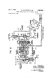
- Figure 1 is a schematic diagram illustrating a system fer controlling the starting of an aircraft engine
- Figure 2 is a schematic diagram illustrating a system' for controlling the speed of a turbine driven engine inA flight of the aircraft.
- a primary power source and control therefor and by the numeral 2 there is schematically illustrated a secondary power source, con trol system and engine carried by a projectile or guided missile and which may be detached from the primary power source 1 through detachable connectors of suitable type indicated generally by the numerals 5, 7, 9, 11, and 13.
- the primary power source and control 1 includes a control switch having an operator-operative lever 17 manually operable in a counter-clockwise direction t0 cause switch element 19 to close contact 20.
- the switch element 19 is normally biased by a suitable spring to an open position.
- the lever 17 may be also operated in an opposite clockwise direction to cause switch element 21 to close contact 23.
- the switch element 21 is normally biased by a suitable spring to an open position.
- the switch Contact 211 is connected by a conductor 25 to an output conductor 27' of an A. C. generator 29, while another output conductor 31 of the generator 29 is connected by conductor 33 to the contact 23 of the control switch 1.5.
- the generator 29 is driven through shaft 35 by suitable power means, such as an electrical motor 37 energized by a suitable source of electrical energy indicated herein as battery 39 connected to the motor through a suitable rheostat 41.
- the output lines 27 and 31 of the generator 29 are in turn connected through the detachable connectors 7 and 5 to lines 43 and 45 respectively in the control system 2.
- the control switch elements 19 and 21 are in turn connected through conductors 51 and 53 through thedetachable connectors 11 and 13 to conductors 55 and 57 in the control system 2.
- the conductor 5'? is in turn connected to contact 61 controlled by switch element 63 biased into a contact closing position by spring element 65.
- the switch element o3 is in turn connected by conductors 67 and 69 to solenoid controlled valves 71 and 73.
- the opposite terminal of the respective control solenoids for the valves 71 and 73 being connected by conductors 75 and 77 to a conductor 79 leading to the output conductor 45.
- Energization of the respective control solenoids in the valves 71 and 73 causes the opening of such valves while upon deeuergization of the control solenoids the valves 71 and 73 assume a normal closed valve position.
- the electrical conductor 57 is also connected through a conductor S1 to a switch arm d3 operated by a pressure bellows 85.
- the interior of the bellows a" is connected through a conduit 37 to the interior of combustion chamber 89 of an engine 911.
- the combustion chamber 89 has a nozzle 91 for directing combustion gases so as to drive a turbine 92 of the engine 90, as hereinafter explained.
- the pressure responsive bellows 8S is normally biased by spring 95 in a direction causing switch arm 83 to close contact 97 which contact is connected through a conductor 99 to one side of an ignition coil 101.
- ⁇ opposite input side of the ignition coil 101 isl connected by conductor 1113 to the conductor 79 leading to output conductor 4.5 through an overspeed control switch 104 biased by spring 105 to a position closing contact 106 so as to connect conductor 79 to conductor 45.
- Conductors 1117 and 1119 lead from the output of the ignition coil 1111 to a spark plug or other suitable igniter 111 projecting into the combustion chamber 89 for ignition of fuel supplied thereto, as hereinafter explained. It
- Solenoid controlled valve 71 controls a conduit 12d leading from the fuel tanlfL 123 to a supply conduit 125 which in turn is connected through a check valve 127 and conduit 129 t a fuel metering nozzle 13d projecting into the comH bustion chamber 89;
- the conduit 125 is also connected to the fuel nozzle 130 through a suitable fuel flow valve 131 and fuel pressure valve 133.
- the speed of the engine 9'@ may be reg* ulated ⁇ through operation of suitable mechanism responsive to the driven speed of the engine 9@ controlling the fuel flow control valve 131 and the adjuste-d position of the nozzle 91 relative to turbine 92, 1as shown in Figure 2 and explained hereinafter.
- the valve 133 has a higher fuel pressure setting than check valve 127 and is unaffected by the combustion pressure from chamber 89. rl ⁇ he valve 133 is so arranged as to remain closed until the fuel pressure in line 125 has exceeded the pressure set ⁇ ting of the valve 133 causing the valve 133 to open.
- the valve f3 contro-ls the conduit li-l1 leading from the compressed air bottle 143 so that upon energization of the solenoid controlling the Valve 73, the valve 73 opens the conduit 141 to the conduit 1455 leading through an air pressure regulator valve 147 of a suitable type to an air conduit 149 which in turn leads through a pressure differential valve 151, conduit 153, and air metering device 155, of a suitable type, and conduit 157 into the combustion chamber S9.
- the air is thus directed about the fuel metering nozzle 130 so as to effect ignition and combustion of fuel supplied the combustion chamber through nozzle 130.
- Air under high pressure fro-m the compressed air bottle 143 is also directed by -air conduit 161 leading from the conduit 149 to one side of fuel tank 123 so as to cause a suitable piston 163 to be pressurized so as to force a starting surge of fuel from the opposite side of the fuel tank 123 through conduit 12), solenoid controlled valve 71, conduit 125, check valve 127 and conduit 129 into the combustion chamber 89 through the fuel metering nozzle 13d.
- solenoid controlled valve 71 conduit 125, check valve 127 and conduit 129 into the combustion chamber 89 through the fuel metering nozzle 13d.
- temporary flow of starting air is supplied to the decomposition chamber 89 through the conduit 153 and the air metering device 155.
- Combustion of the fuel and air mixture in the combustion chamber il@ is initiated by the igniter 111 which is simultaneously excited upon energization of the solenoids controlling the valves 71 and 73 by the closing of switch element 19 through operation of the manually operable control lever 17.
- the rise in the chamber pressure causes the pressure responsive bellows S to actuate the switch arm 83 in a counter-clockwise direction to close Ia contact 171 and in turn connect conductor 31 to the output conductor t3 through a conductor 175.
- thel antibiotic in chamber pressure closes the pressure differential valve 151 and the fuel check valve 127 thereby halting the flows of starting air and starting fuel.
- the main fuel supply to the combustion chamber 59 is then fed through the fuel flow control valve 131 under control of an engine speed responsive mechanism shown in Figure 2 and hereinafter explained.
- the turbine 92 driven by combustion gases applied through nozzle 91 in turn drives shaft 163 for driving a second shaft 1&3 and a generator 185 which provides a secondary power source.
- T he output of generator 185 is also connected across the lines 4l5 and 4.3 heretofore described.
- the secondary power source or generator becomes the sole source of supply of electrical energy for the projectile.
- a conventional fly-ball speed governor 190 driven from shaft 183 by a shaft 191 is arranged to operate, through a pin 192, the switch 104 so as to open the conductor 79 and shut the system down under excessive emergency speed conditions.
- the closing of the switch contact 171 by the switch arm 83 will cause, upon a detachment of the projectile from the primary source 1, the secondary source 2 to maintain energization of the respective control valves 71 and 73 so as to permit the supply of fuel and air to the combustion chamber 89 of the engine 90 which may provide an auxiliary source of power for control purposes to be used in a guided missile or projectile or such engine could be used as the primary source of power to carry the projectile or guided missile to its destination.
- the engine is controlled by the speedcontrol mechanism, shown in Figure 2, and hereinafter described and explained.
- the rising decomposition pressure in chamber e9 also causes bellows 35 to actuate the arm 53 so as to close contact 1"/'1 which connects the control solenoi-,ds of valves 71 and 73 to the power lines i5- d5 and in parallel to the power lines 27-31 of the primary power source 1 of the mother aircraft or other launching means for the projectile lor missile 2.
- the valves 71 and 73 are connected to the power lines t3-45 carried by the missile 2 for later disconnection through discon nectors 5, 7, 9, 11 and 15 from the electrical system of the mother aircraft or launching means and energization solely by generator carried by the projectile or missile 2.
- overspeed governor' 190 is provided to actuate the overspeed switch ft so that the electrical line 79 feeding the solenoids controlling the air and fuel control valves 71 and 73 is broken causing the valves 71 and 73 to be actuated to a closed position.
- control lever 17 may be thrown in a clockwise direction by the operator to an off position so as to cause switch element 21 to close contact 23 energizing relay winding .196 causing switch arm 63 to open contact 61 and interrupting the supply of electrical energy to the solenoids controlling the lfuel and air control Valves 71 and 73 whereupon the valves 7'1 and 73 are actuated to a closed position.
- Combustion of the fuel and air mixture in the decomposition chamber 89 is initiated by a conventional ignition spark from the spark plug 111. Upon combustion, the rise in pressure in chamber 89 closes the pressure differential valve 151 and the fuel check valve 127, thereby halting the flows of starting air and starting fuel.
- the main fuel supply to the combustion chamber 89 is then controlled through valves 133 and 131 in which its flow is regulated through valve 131 by the turbine speed control mechanism of Figure 2.
- the speed control mechanism is shown in detail in Figure 2 and is designed for use with the mechanism of Figure l wherein like numerals indicate corresponding parts.
- the combustion chamber 89 is shown schematically as pivotally supported at 200 by a bracket 203 and adjustably positioned through a linkage 205, rod 207 and piston 209 slidably mounted in a chamber 211.
- the rod 207 aiiiXed to the piston 209 projects from one end of the chamber 211 while a second rod 212 aiiixed to the piston 209 projects from the opposite end of the chamber 211.
- the rod 212 is in turn affixed to a valve element 214 slidably mounted in the fuel flow control valve 131 and controlling the flow of fuel through the conduit 125 which is connected to the combustion chamber 89 through a flexible coupling 216 so as to permit adjustment of the combustion chamber 89 and the nozzle 91 relative to the turbine 92 by the piston 209.
- Pivotally connected at 220 to the piston rod 212 is a beam 222 which is pivotally connected in turn at 224 and 226 to rods 228 and 230.
- the rod 228 is adjustably positioned by a piston 231 slidably mounted in the piston chamber 232.
- the piston rod 228 is aixed to one side of the piston 231 and projects from one end of the chamber 232, while a second rod 235 is afnxed to the other side of the piston 231 and projects from an opposite end of the chamber 232.
- the piston 231 may thereby adjustably position through beam 222 the rod 230 which is in turn aixed to a servo valve 234 controlling selectively the conduits 238 and 240 leading from the servo valve chamber 241 and f thereby the application of servo fluid pressure applied through conduit 242 to piston 209 and the drainage of servo fluid from one side or the other of the piston 209 in the chamber 211 through the drainage conduits 244 and 246.
- valve 230 is slidably mounted in a valve sleeve 250 which is in turn slidably mounted in the Valve chamber 241.
- a spring 251 biases the valve sleeve 250 upwardly and cooperates with the servo valve 234 to control the conduits 238 and 240.
- a variable fluid pressure is applied to a chamber 252 at the upper end of the valve sleeve 250 and acts in opposition to the biasing force of the spring 251.
- the chamber 252 is connected by conduit 254 to the outlet of a suitable hydraulic pump 260 having a fluid inlet conduit 262.
- the pump 260 is driven by the shaft 163 of .the turbine 92 so as to supply through conduit 254 oil or other suitable hydraulic medium to the chamber 252 under a fluid pressure proportional to the driven u spring 251.
- the spring 251 tends to biasthe sleeve 250 in an upward direction against the decreasing biasing force of the hydraulic uid medium in the chamber 252.
- Such upward adjustment of the valve 234 will in turn cause an adjustment of the piston 209 in a downward direction tending to actuate the combustion chamber 89 and nozzle 91 vin a counter-clockwise direction decreasing the speed of the turbine 92.
- Such downward adjustment of the piston 209 will also simultaneously cause anadjustment of the fuel flow control valve 214 in a downward direction tending to decrease the supply of fuel through line to the combustion chamber 89 so as Vto act in a sense to decrease the driven speed of the turbine 92.
- Adjustment of the control piston 231 in an opposite downward sense will cause an opposite adjustment of the valve 234, combustion chamber 89 and fuel control valve 214 to increase the speed of the turbine 92.
- Controlling the operation of the piston 231 is a governor booster servo mechanism indicated generally by the nu meral 275 and including a casing 277 and drainage passage 280, together with fluid pressure control lines 282 and 283 leading to opposite sides of the piston 231.
- the fluid pressure control line 282 is supplied with fluid aseaese U medium by a pressure line leading through a restriction 286 to the line 282 and which line 282 has in turn a controlled valve opening 288.
- the line 283 is supplied with fluid pressure medium from the line 284 through a restriction 290 and which line 283 has in turn a controlled valve opening 292.
- valve openings 200 and 292 are arranged in opposite relation and are arranged to be alternately opened and closed by valve element 294 mounted on arm 296 pivotally mounted within the casing 277 at a point 298.
- a linkage arm 300 pivotally connected exteriorly of the casing at a point 301 to an actuator arm 302.
- the linkage 300 is operatively connected to the arm 302 at a point intermediate the opposite ends thereof.
- One end of the arm 302 is pivotally connected at 303 to a rod 235 of the piston 231.
- the opposite end 305 of the arm 302 is resiliently supported at 305 by spring elements 3,07 and 309 bearing on Ithe arm 305 at the opposite sides thereof.
- the spring 309 is supported by an element 3M which is adjustably positioned through operation of a fly-ball governor 313 having weighted elements 3M of conventional type and driven through gearing 315 by shaft 183 from the turbine driven shaft 263.
- the spring 307 at the other side of the end 305 of lever 302 has an end supported by an element 320 which may be adjustably positioned by an actuating screw 322 in turn driven by servomotor 324 through shaft 326.
- the servornotor 324 may be controlled manually by the operator by suitable switch elements 330-3311 or by a suitable control circuit not shown and arranged toV adljust the speed setting of the fly-ball governor 313 to a desired value.
- the weights 3M- of the ily-ball governor 313 will move inwardly under force of a spring 331 so as to. in turn cause the lever 302 to be moved in a clockwise direction, causing the adjustment of the valve 294 to close valve opening 23S and open valve opening 292, and in turn moving the piston 2.31 in a downward direction to effect an increase of the speed of the turbine 92 back to the desired value.
- the piston 209 is connected by rod 2l2 to the fuel metering valve 214 and determines the position thereof and hence the amount of fuel flowing to the combustion or decomposition chamber 39.
- Rod 207 is also connected to the piston 209 so that simultaneously with the adjustment of fuel valve l214i the position of the combustion chamber 89 and exhaust gas nozzle 9i are also adjustably positioned relative to the turbine 92 through linkage 205. ln ⁇ this Way the speed of the prime mover or turbine 92 is controlled both by the adjusted position of the fuel metering control valve 214- and by the adjusted position of the decomposition chamber 89 relative to the turbine 92.
- the combination comprising a turbine, a combustion chamber having an exhaust gas nozzle, said combustion chamber and said gas nozzle being adjustable relative to said turbine to vary the driven speed thereof, an adjustable valve means to vary the supply of fuel to said combustion chamber, motor means for simultaneously adjusting said exhaust gas nozzle and valve means to Vary the speed of said turbine first means responsive to a condition of operation related to power output of said turbine operatively connected to said motor means for 'controlling said motor means in accordance with variations from a preselected value of said condition of operation, and second means responsive to said condition of operation related to power output operatively connected to said motor means, said second means being operative to terminate the effect of said first means on said motor means when said preselected value is attained.
- the combination comprising a turbine, a combustion chamber having an exhaust gas nozzle, said combus- -tion chamber and said gas nozzle being adjustable relative to said turbine to vary the driven speed thereof, an adjustable valve means to vary the supply of fuel to said combustion chamber, motor means for simultaneously adjust- ⁇ 'ing said exhaust gas nozzle and valve means to vary the speed of said turbine, servo-valve ⁇ means for controlling said motor means, turbine speed responsive means, said servo valve means including a rst control element operatively connected to said turbine speed responsive means to regulate the driven speed of said turbine to a preselected value, another turbine speed responsive means, said servovalve means including a second control element operatively connected to said other turbine speed responsive means to effect control of said servo-valve means to a null position.
- a combustion chamber having an exhaust gas nozzle, a turbine driven by exhaust gases from said nozzle, a lluid fuel inlet conduit to said combustion chamber, valve means to control said fuel conduit, servomotor means including a piston having an actuating rod operatively connected to said valve means, means pivotally mounting said combustion chamber foradjustment of said chamber and exhaust gas nozzle relative to said turbine to vary the impingement of exhaust gases on said turbine, said motor means having another actuating rod operatively connecting said piston to said combustion chamber for the adjustment thereof, and turbine speed responsive means for controlling said piston so as to regulate the speed of the turbine.
- a combustion chamber having an exhaust gas nozzle, a turbine driven by exhaust gases from said nozzle, a fluid fuel inlet conduit to said combustion chamber, valve means to control said fuel conduit
- servomotor means including a piston having an actuating rod operatively connected to said valve means, means pivotally mounting said combustion :chamber for adjustment of said chamber and exhaust gas nozzle relative to said turbine to vary the impingement of exhaust gases on said turbine, said motor means having another actuating rod operatively connecting said piston to said combustion chamber for the adjustment thereof
- servo valve means including a first adjustable control element and a second adjustable control element, said rst and second control elements cooperating in controlling the adjusted position of said piston, rst speed responsive means for adjusting said lrst control element upon a change in the driven speed of said turbine from a selected value, and a second speed responsive means for adjusting said second control element upon change in said turbine speed in response to the adjustment of said rst control element.
- the combination comprising a turbine, a combustion chamber having an exhaust gas nozzle adjustable relative to said turbine to vary the driven speed thereof, an adjustable valve means to vary the supply of fuel to said combustion chamber, engine operating condition responsive means for simultaneously adjusting both said valve means and said exhaust gas nozzle so as to maintain a predetermined engine operating condition, said engine operating condition responsive means including an engine speed responsive means to etect simultaneous adjustment of both saidl valve means and exhaust gas nozzle so as to regulate the engine speed to a preselected value, and means for sensing the turbine output load, said means being operable to cause a modification in said preselected engine speed value according to increasing or decreasing load conditions.
Description
. SPEED CONTROL SYSTEM FOR GAS TURBINE ENGINES Y Filed March 3l, 1955 ec.. 9, 1958 H. R. scHMlDER ETAL {Sheets-Sheet 1 Dec. 9 1958 H'. n. scHMlDER ETAL 263,283 SPEED CONTROL SYSTEM FOR GAS TURBINE ENGINES Filed March 3l, 1955 2 Sheets-Sheet 2 States arent (2,863,283 Patented Dec. 9, 1958 .wifi
SPEED CONTROL SYSTEM FOR GAS TURBINE ENGINES Henry R. Schmider, Clifton, N. J., Edward C. Paimenberg, Nanuet, N. Y., and William J. Dietz, Jr., Hillsdaie, N. J., assignors to Bendix Aviation Corporation, 'feteru boro, N. J., a corporation of Delaware Application March 31, 1955, Serial No. 498,235 5 Claims. (Cl. 611-3924) The present application relates to a novel dual type control system and method for inducing combustion and controlling decomposition of monopropellant fuels such as propyl nitrate, ethylene oxide and hydrazine so as to produce impulses for operating gas driven devices for providing an auxiliary power supply for an aircraft or for driving an aircraft, guided missile or projectile and for controlling the flow of fuel to a combustion chamber and the impingement of the generated gases against a turbine after the initial starting operation thereof, Decomposition of such a fuel is initiated by the combination `of an oxidizing agent and fuel in the presence of an igniter and after the initial starting operation has been effected, ignition of the fuel supplied the chamber continues through the action of the ignited fuel in the chamber.
Broadly the subject invention involves improvements in a fuel control system of a type such as disclosed and claimed in U. S. application Serial No. 249,532, tiled October 3, 1951, by Emil A. Volk, Jr., and Walter D.
`Teague, Jr.; U. S. application Serial No. 328,988 now Patent No. 2,742,759 tiled December 3l, 1952, by Cameron D. Flanigen and William John Dietz, lr.; U. S. application Serial No. 329,048 now Patent No. 2,742,758 led December 3l, 1952, by Jack J. Kelly; and application Serial No. 329,063 now Patent No. 2,742,757 tiled December 3l, 1952, by John S. Jaquith and which applica-tions have been assigned to Bendix Aviation Corpora tion, the assignee of the present application.
An object of the invention is to provide a novel control system for regulating the speed of a combustion engine in a projectile or guided missile during flight of the aircraft.
Another object of the invention is to provide a novel control for regulating the driven speed of a prime mover by varying both the gas impingement on the prime mover and the quantity of fuel supplied the combustion chamber so as to effect a dual control efficiently regulating the speed of the prime mover.
Another object of the invention is to provide a novel control system for effecting fuel economy as well as providing for variation in gas impingement on the prime mover in regulating the driven speed of the prime mover.
Another object of the invention is to provide a method of regulating the driven speed of a turbine by controlling both the quantity of fuel supplied the combustion chamber and the location of the combustion chamber and exhaust outlet thereof relative to the turbine so as to effectively regulate the driven speed thereof.
The above and other objects and'features of the invention will appear more fully hereinafter from a consideration of the following description taken in connection with the accompanying drawing wherein one embodiment of the invention is illustrated by way of eX- ample:
In the drawings: Y
Figure 1 is a schematic diagram illustrating a system fer controlling the starting of an aircraft engine,
Figure 2 is a schematic diagram illustrating a system' for controlling the speed of a turbine driven engine inA flight of the aircraft.
Referring now to the drawing of Figure l, there is indicated generally by the numeral 1, a primary power source and control therefor and by the numeral 2 there is schematically illustrated a secondary power source, con trol system and engine carried by a projectile or guided missile and which may be detached from the primary power source 1 through detachable connectors of suitable type indicated generally by the numerals 5, 7, 9, 11, and 13.
The primary power source and control 1 includes a control switch having an operator-operative lever 17 manually operable in a counter-clockwise direction t0 cause switch element 19 to close contact 20. The switch element 19 is normally biased by a suitable spring to an open position. The lever 17 may be also operated in an opposite clockwise direction to cause switch element 21 to close contact 23. The switch element 21 is normally biased by a suitable spring to an open position.
The switch Contact 211 is connected by a conductor 25 to an output conductor 27' of an A. C. generator 29, while another output conductor 31 of the generator 29 is connected by conductor 33 to the contact 23 of the control switch 1.5. The generator 29 is driven through shaft 35 by suitable power means, such as an electrical motor 37 energized by a suitable source of electrical energy indicated herein as battery 39 connected to the motor through a suitable rheostat 41. The output lines 27 and 31 of the generator 29 are in turn connected through the detachable connectors 7 and 5 to lines 43 and 45 respectively in the control system 2. The control switch elements 19 and 21 are in turn connected through conductors 51 and 53 through thedetachable connectors 11 and 13 to conductors 55 and 57 in the control system 2. The conductor 5'? is in turn connected to contact 61 controlled by switch element 63 biased into a contact closing position by spring element 65.
The switch element o3 is in turn connected by conductors 67 and 69 to solenoid controlled valves 71 and 73. The opposite terminal of the respective control solenoids for the valves 71 and 73 being connected by conductors 75 and 77 to a conductor 79 leading to the output conductor 45. Energization of the respective control solenoids in the valves 71 and 73 causes the opening of such valves while upon deeuergization of the control solenoids the valves 71 and 73 assume a normal closed valve position.
The electrical conductor 57 is also connected through a conductor S1 to a switch arm d3 operated by a pressure bellows 85. The interior of the bellows a" is connected through a conduit 37 to the interior of combustion chamber 89 of an engine 911. The combustion chamber 89 has a nozzle 91 for directing combustion gases so as to drive a turbine 92 of the engine 90, as hereinafter explained.
The pressure responsive bellows 8S is normally biased by spring 95 in a direction causing switch arm 83 to close contact 97 which contact is connected through a conductor 99 to one side of an ignition coil 101. The
` opposite input side of the ignition coil 101 isl connected by conductor 1113 to the conductor 79 leading to output conductor 4.5 through an overspeed control switch 104 biased by spring 105 to a position closing contact 106 so as to connect conductor 79 to conductor 45.
Conductors 1117 and 1119 lead from the output of the ignition coil 1111 to a spark plug or other suitable igniter 111 projecting into the combustion chamber 89 for ignition of fuel supplied thereto, as hereinafter explained. It
will be seen then that upon operation of the lever 17 of the switch 15 in a counter-clockwise direction so as to cause switch element 19 to close contact 245, the control valves '71 and 73 will be actuated to an open valve position, while the. ignition coil lill will be energized causing the igniter 111 to be excited to effect ignition of fuel supplied to the combustion chamber 89. Solenoid controlled valve 71 controls a conduit 12d leading from the fuel tanlfL 123 to a supply conduit 125 which in turn is connected through a check valve 127 and conduit 129 t a fuel metering nozzle 13d projecting into the comH bustion chamber 89;
The conduit 125 is also connected to the fuel nozzle 130 through a suitable fuel flow valve 131 and fuel pressure valve 133. After combustion in the chamber 89 has been initiated, the speed of the engine 9'@ may be reg* ulated` through operation of suitable mechanism responsive to the driven speed of the engine 9@ controlling the fuel flow control valve 131 and the adjuste-d position of the nozzle 91 relative to turbine 92, 1as shown in Figure 2 and explained hereinafter. The valve 133 has a higher fuel pressure setting than check valve 127 and is unaffected by the combustion pressure from chamber 89. rl`he valve 133 is so arranged as to remain closed until the fuel pressure in line 125 has exceeded the pressure set` ting of the valve 133 causing the valve 133 to open.
The valve f3 contro-ls the conduit li-l1 leading from the compressed air bottle 143 so that upon energization of the solenoid controlling the Valve 73, the valve 73 opens the conduit 141 to the conduit 1455 leading through an air pressure regulator valve 147 of a suitable type to an air conduit 149 which in turn leads through a pressure differential valve 151, conduit 153, and air metering device 155, of a suitable type, and conduit 157 into the combustion chamber S9. The air is thus directed about the fuel metering nozzle 130 so as to effect ignition and combustion of fuel supplied the combustion chamber through nozzle 130.
Air under high pressure fro-m the compressed air bottle 143 is also directed by -air conduit 161 leading from the conduit 149 to one side of fuel tank 123 so as to cause a suitable piston 163 to be pressurized so as to force a starting surge of fuel from the opposite side of the fuel tank 123 through conduit 12), solenoid controlled valve 71, conduit 125, check valve 127 and conduit 129 into the combustion chamber 89 through the fuel metering nozzle 13d. Similarly temporary flow of starting air is supplied to the decomposition chamber 89 through the conduit 153 and the air metering device 155.
Combustion of the fuel and air mixture in the combustion chamber il@ is initiated by the igniter 111 which is simultaneously excited upon energization of the solenoids controlling the valves 71 and 73 by the closing of switch element 19 through operation of the manually operable control lever 17. the rise in the chamber pressure causes the pressure responsive bellows S to actuate the switch arm 83 in a counter-clockwise direction to close Ia contact 171 and in turn connect conductor 31 to the output conductor t3 through a conductor 175.
Upon combustion in the chamber S9, thel risc in chamber pressure closes the pressure differential valve 151 and the fuel check valve 127 thereby halting the flows of starting air and starting fuel. The main fuel supply to the combustion chamber 59 is then fed through the fuel flow control valve 131 under control of an engine speed responsive mechanism shown in Figure 2 and hereinafter explained.
The turbine 92 driven by combustion gases applied through nozzle 91 in turn drives shaft 163 for driving a second shaft 1&3 and a generator 185 which provides a secondary power source. T he output of generator 185 is also connected across the lines 4l5 and 4.3 heretofore described.
Upon the engine of the projectile or guided missile .being driven at sufficient speed to cause the projectile or Upon combustion in the chamber 89 l guided missile to detach itself from the primary source 1, the secondary power source or generator becomes the sole source of supply of electrical energy for the projectile.
A conventional fly-ball speed governor 190 driven from shaft 183 by a shaft 191 is arranged to operate, through a pin 192, the switch 104 so as to open the conductor 79 and shut the system down under excessive emergency speed conditions.
Further, the closing of the switch contact 171 by the switch arm 83 will cause, upon a detachment of the projectile from the primary source 1, the secondary source 2 to maintain energization of the respective control valves 71 and 73 so as to permit the supply of fuel and air to the combustion chamber 89 of the engine 90 which may provide an auxiliary source of power for control purposes to be used in a guided missile or projectile or such engine could be used as the primary source of power to carry the projectile or guided missile to its destination. After initiation of the starting operation, the engine is controlled by the speedcontrol mechanism, shown in Figure 2, and hereinafter described and explained.
Should it be desired after initiating operation of the control system to shut the same down before the projectile has detached itself from the primary power source, this may be readily effected by pushing the switch arm 17 in a clockwise direction so as to cause switch element 21 to close contact 23. The latter action causes energization of -electrornagnet 196 connected across conductor 55 and conductor 193 leading to the conductor 25,
Energization of the electromagnetic winding 196 will thereupon -actuate the switch 63 to an open position against the biasing force of the spring 65 causing in turn the deenergization of the respective solenoids controlling the valves 71 `and 73 and v-deenergization of ignition coil 101.
When the unit is thus shut down, fuel flow tothe combustion chamber 359 and the pressurizing air to the fuel tank 123 is shut olf by the respective solenoid controlled valves 71 and 73. A portion of the air trapped inthe line 161 at the air side. of the fuel tank 123 is bled off through the pressure differential valve 151 and conduit 153 so `as topurge the combustion chamber 89 of any residual combustion products. The use of the pressure differential valve 151 instead of a conventional checlc valve effects a saving of compressed air for restarting since a major portion of the compressed air will` remain in the `compressed air side of the tank 123.
Operation of z/'te starring control system ln view of the foregoing, it will be seen that upon operation of the starting switch lever 17 so as to close switch element 19 electrical power is supplied through normally closedk contacts 83,-.97 of a pressure switch controlled by bellows 85 (which senses decomposition chamber 89 pressure) to the spark plug 111 and through normally closed relay contacts dil-63 to the air and fuel solenoid controlled valves 71 and 73. As decomposition is initiated, the chamber 89 pressure rises to a value which causes bellows 85 to open the normally closed contacts 83--97 of the pressure switch stops the action of the spark` plug 111. Further with the latter action, the rising decomposition pressure in chamber e9 also causes bellows 35 to actuate the arm 53 so as to close contact 1"/'1 which connects the control solenoi-,ds of valves 71 and 73 to the power lines i5- d5 and in parallel to the power lines 27-31 of the primary power source 1 of the mother aircraft or other launching means for the projectile lor missile 2. Thus the valves 71 and 73 are connected to the power lines t3-45 carried by the missile 2 for later disconnection through discon nectors 5, 7, 9, 11 and 15 from the electrical system of the mother aircraft or launching means and energization solely by generator carried by the projectile or missile 2. In the event the generator 185 is driven by turbine 92 in excess of a predetermined safe value, overspeed governor' 190 is provided to actuate the overspeed switch ft so that the electrical line 79 feeding the solenoids controlling the air and fuel control valves 71 and 73 is broken causing the valves 71 and 73 to be actuated to a closed position.
in order to shut the system off during normal opera tion priorto flight of the missile or projectile 2, the control lever 17 may be thrown in a clockwise direction by the operator to an off position so as to cause switch element 21 to close contact 23 energizing relay winding .196 causing switch arm 63 to open contact 61 and interrupting the supply of electrical energy to the solenoids controlling the lfuel and air control Valves 71 and 73 whereupon the valves 7'1 and 73 are actuated to a closed position.
Energization of the solenoids controlling the fuel and air control valves 71 and '73 by closing switch element 19 pressurizes the fuel system and opens the starting fuel valve 71 to the decomposition chamber S9 while high pressure air from the supply tank 143 pressurizes the piston type fuel ask 123 and caus piston 163 to force from the flask 123 a starting charge of fuel through a check valve 127 and metering nozzle 130 into the decomposition chamber 89. Simultaneously, temporary flow of starting air is supplied to the decomposition `chamber 89 through a pressure differential valve 151 and metering device 155.
Combustion of the fuel and air mixture in the decomposition chamber 89 is initiated by a conventional ignition spark from the spark plug 111. Upon combustion, the rise in pressure in chamber 89 closes the pressure differential valve 151 and the fuel check valve 127, thereby halting the flows of starting air and starting fuel. The main fuel supply to the combustion chamber 89 is then controlled through valves 133 and 131 in which its flow is regulated through valve 131 by the turbine speed control mechanism of Figure 2.
When the unit is shut down by the closing of switch element 21, fuel flow into the decomposition chamber 89 and pressurizing air to the fuel ask 123 is shut off by the closing of valves 71 and 73. The air trapped in the conduits 161Aand 149 leading to the fuel flask 123 is bledoif through the pressure differential valve so as to purge the decomposition chamber 89.
Features of the starter control system herein before described are disclosed and claimed in a copending application Serial No. 498,391 filed March 3l, 1955, by Henry R. Schmider, Edward C. Palmer-berg and William I. Dietz, Ir.
Speer! control mechanism The speed control mechanism is shown in detail in Figure 2 and is designed for use with the mechanism of Figure l wherein like numerals indicate corresponding parts. Referring then to Figure 2, the combustion chamber 89 is shown schematically as pivotally supported at 200 by a bracket 203 and adjustably positioned through a linkage 205, rod 207 and piston 209 slidably mounted in a chamber 211. The rod 207 aiiiXed to the piston 209 projects from one end of the chamber 211 while a second rod 212 aiiixed to the piston 209 projects from the opposite end of the chamber 211.
The rod 212 is in turn affixed to a valve element 214 slidably mounted in the fuel flow control valve 131 and controlling the flow of fuel through the conduit 125 which is connected to the combustion chamber 89 through a flexible coupling 216 so as to permit adjustment of the combustion chamber 89 and the nozzle 91 relative to the turbine 92 by the piston 209.
Pivotally connected at 220 to the piston rod 212 is a beam 222 which is pivotally connected in turn at 224 and 226 to rods 228 and 230. The rod 228 is adjustably positioned by a piston 231 slidably mounted in the piston chamber 232. The piston rod 228 is aixed to one side of the piston 231 and projects from one end of the chamber 232, while a second rod 235 is afnxed to the other side of the piston 231 and projects from an opposite end of the chamber 232.
The piston 231 may thereby adjustably position through beam 222 the rod 230 which is in turn aixed to a servo valve 234 controlling selectively the conduits 238 and 240 leading from the servo valve chamber 241 and f thereby the application of servo fluid pressure applied through conduit 242 to piston 209 and the drainage of servo fluid from one side or the other of the piston 209 in the chamber 211 through the drainage conduits 244 and 246.
The valve 230 is slidably mounted in a valve sleeve 250 which is in turn slidably mounted in the Valve chamber 241. A spring 251 biases the valve sleeve 250 upwardly and cooperates with the servo valve 234 to control the conduits 238 and 240. A variable fluid pressure is applied to a chamber 252 at the upper end of the valve sleeve 250 and acts in opposition to the biasing force of the spring 251.
The chamber 252 is connected by conduit 254 to the outlet of a suitable hydraulic pump 260 having a fluid inlet conduit 262. The pump 260 is driven by the shaft 163 of .the turbine 92 so as to supply through conduit 254 oil or other suitable hydraulic medium to the chamber 252 under a fluid pressure proportional to the driven u spring 251. However, upon a decrease in the speed of the turbine 92 there is effected a decrease in such pressure and the spring 251 tends to biasthe sleeve 250 in an upward direction against the decreasing biasing force of the hydraulic uid medium in the chamber 252.
It will be seen from the foregoing that adjustment of the control piston 231 in an upward direction will cause the corresponding upward adjustment of valve 234 so as to effect an application of a servo fluid pressure medium to the piston 209 through lthe line 238 and drainage of the fluid medium at the underside of the piston 209 through the passage 240 and conduit 244.
Such upward adjustment of the valve 234 will in turn cause an adjustment of the piston 209 in a downward direction tending to actuate the combustion chamber 89 and nozzle 91 vin a counter-clockwise direction decreasing the speed of the turbine 92. Such downward adjustment of the piston 209 will also simultaneously cause anadjustment of the fuel flow control valve 214 in a downward direction tending to decrease the supply of fuel through line to the combustion chamber 89 so as Vto act in a sense to decrease the driven speed of the turbine 92.
Further, such a decrease in the speed of the turbine 92 will cause a decrease in the fluid pressure applied to the chamber 252 tending to cause the valve sleeve 250 under force of the spring 251 to move upwardly so as to provide a followup action tending to follow the adjustment of the valve 234, heretofore described, so as to tend to terminate the supply of hydraulic fluid applied through the channel 238 to the piston 209.
Adjustment of the control piston 231 in an opposite downward sense will cause an opposite adjustment of the valve 234, combustion chamber 89 and fuel control valve 214 to increase the speed of the turbine 92.
Controlling the operation of the piston 231 is a governor booster servo mechanism indicated generally by the nu meral 275 and including a casing 277 and drainage passage 280, together with fluid pressure control lines 282 and 283 leading to opposite sides of the piston 231. The fluid pressure control line 282 is supplied with fluid aseaese U medium by a pressure line leading through a restriction 286 to the line 282 and which line 282 has in turn a controlled valve opening 288.
Similarly, the line 283 is supplied with fluid pressure medium from the line 284 through a restriction 290 and which line 283 has in turn a controlled valve opening 292.
As shown in Figure 2, the controlled valve openings 200 and 292 are arranged in opposite relation and are arranged to be alternately opened and closed by valve element 294 mounted on arm 296 pivotally mounted within the casing 277 at a point 298.
Operatively positioning the valve 294 relative to. the valve openings 208: and 292 is a linkage arm 300 pivotally connected exteriorly of the casing at a point 301 to an actuator arm 302. The linkage 300 is operatively connected to the arm 302 at a point intermediate the opposite ends thereof. One end of the arm 302 is pivotally connected at 303 to a rod 235 of the piston 231.
The opposite end 305 of the arm 302 is resiliently supported at 305 by spring elements 3,07 and 309 bearing on Ithe arm 305 at the opposite sides thereof. The spring 309 is supported by an element 3M which is adjustably positioned through operation of a fly-ball governor 313 having weighted elements 3M of conventional type and driven through gearing 315 by shaft 183 from the turbine driven shaft 263.
The spring 307 at the other side of the end 305 of lever 302 has an end supported by an element 320 which may be adjustably positioned by an actuating screw 322 in turn driven by servomotor 324 through shaft 326. The servornotor 324 may be controlled manually by the operator by suitable switch elements 330-3311 or by a suitable control circuit not shown and arranged toV adljust the speed setting of the fly-ball governor 313 to a desired value.
From the foregoing it will be seen that upon the speed of the turbine increasing eyond the value for which the spring 307 is set, weights 3M will be thrown outwardly by centrifugal force so as to pull the element 3l1 downwardly causing the arm 302 to be adjusted in a counterclockwise direction so as to in turn close the valve opening 292 and open the valve opening 288, so that greater duid pressure may be applied through passage 283 causing an upward adjustment of the piston 231. Such action will in turn c-ause the piston 209 to adjust the fuel valve 2id and the combustion chamber 89 in a sense to decrease the speed of the turbine 92 to the regulated value.
f course, upon the speed of the turbine 92 decreasing below that for which the spring 3.07 is set, the weights 3M- of the ily-ball governor 313 will move inwardly under force of a spring 331 so as to. in turn cause the lever 302 to be moved in a clockwise direction, causing the adjustment of the valve 294 to close valve opening 23S and open valve opening 292, and in turn moving the piston 2.31 in a downward direction to effect an increase of the speed of the turbine 92 back to the desired value.
lt should also be noted that such adjustment of the arm 302 by the speed governor 313 will cause the piston 231 to actuate through the piston rod 235 the arm 302 vin a sense to follow up the adjustment of the valve 294 and effect a return adjustment thereof to a neutral position. Such follow-up action of the piston 231 on the lever 302 will tend to prevent over-adjustment or hunting in the control 275 and provide stability of control.
Operation of the turbine speed control mechanism From, the forego-ing itwill be seen that the position of piston 209 and rod 21,2 of the control of Figure 2 is determined by the speed governor 313 so that if an increase in speed is called for by the governor 3l3, the arm 222 pivots in a counter-clockwise direction about point 220 and if a decrease in the speed of the turbine 92 lis called for, the arm 222 is pivoted about point 220 in a clockwise direction, as shown schematically in Figure 2. This motion of the arm 222 adjusts the position of the servo valve 234 which selectively feeds servo fluid to either side of the servo piston 209, depending upon whether or not an increase or decrease in the speed of the turbine 92 is required. Further, the piston 209 is connected by rod 2l2 to the fuel metering valve 214 and determines the position thereof and hence the amount of fuel flowing to the combustion or decomposition chamber 39. Rod 207 is also connected to the piston 209 so that simultaneously with the adjustment of fuel valve l214i the position of the combustion chamber 89 and exhaust gas nozzle 9i are also adjustably positioned relative to the turbine 92 through linkage 205. ln` this Way the speed of the prime mover or turbine 92 is controlled both by the adjusted position of the fuel metering control valve 214- and by the adjusted position of the decomposition chamber 89 relative to the turbine 92.
This method of control of the quantity of fuel and location of the decomposition chamber results in a finer control than might otherwise have been achieved. Additionally, there is a considerable fuel saving from this dual control during speeds of low output power.
Although only one embodiment of the invention has been illustrated, various changes can be made in the design and arrangement of the parts without departing from the spirit and scope of the invention as the same will now be understood by those skilled inthe art.
What is claimed is:
l. The combination comprising a turbine, a combustion chamber having an exhaust gas nozzle, said combustion chamber and said gas nozzle being adjustable relative to said turbine to vary the driven speed thereof, an adjustable valve means to vary the supply of fuel to said combustion chamber, motor means for simultaneously adjusting said exhaust gas nozzle and valve means to Vary the speed of said turbine first means responsive to a condition of operation related to power output of said turbine operatively connected to said motor means for 'controlling said motor means in accordance with variations from a preselected value of said condition of operation, and second means responsive to said condition of operation related to power output operatively connected to said motor means, said second means being operative to terminate the effect of said first means on said motor means when said preselected value is attained.
2. The combination comprising a turbine, a combustion chamber having an exhaust gas nozzle, said combus- -tion chamber and said gas nozzle being adjustable relative to said turbine to vary the driven speed thereof, an adjustable valve means to vary the supply of fuel to said combustion chamber, motor means for simultaneously adjust- `'ing said exhaust gas nozzle and valve means to vary the speed of said turbine, servo-valve `means for controlling said motor means, turbine speed responsive means, said servo valve means including a rst control element operatively connected to said turbine speed responsive means to regulate the driven speed of said turbine to a preselected value, another turbine speed responsive means, said servovalve means including a second control element operatively connected to said other turbine speed responsive means to effect control of said servo-valve means to a null position.
3. In an internal combustion engine, the combination comprising a combustion chamber having an exhaust gas nozzle, a turbine driven by exhaust gases from said nozzle, a lluid fuel inlet conduit to said combustion chamber, valve means to control said fuel conduit, servomotor means including a piston having an actuating rod operatively connected to said valve means, means pivotally mounting said combustion chamber foradjustment of said chamber and exhaust gas nozzle relative to said turbine to vary the impingement of exhaust gases on said turbine, said motor means having another actuating rod operatively connecting said piston to said combustion chamber for the adjustment thereof, and turbine speed responsive means for controlling said piston so as to regulate the speed of the turbine.
4. In an internal combustion engine, the combination comprising a combustion chamber having an exhaust gas nozzle, a turbine driven by exhaust gases from said nozzle, a fluid fuel inlet conduit to said combustion chamber, valve means to control said fuel conduit, servomotor means including a piston having an actuating rod operatively connected to said valve means, means pivotally mounting said combustion :chamber for adjustment of said chamber and exhaust gas nozzle relative to said turbine to vary the impingement of exhaust gases on said turbine, said motor means having another actuating rod operatively connecting said piston to said combustion chamber for the adjustment thereof, servo valve means including a first adjustable control element and a second adjustable control element, said rst and second control elements cooperating in controlling the adjusted position of said piston, rst speed responsive means for adjusting said lrst control element upon a change in the driven speed of said turbine from a selected value, and a second speed responsive means for adjusting said second control element upon change in said turbine speed in response to the adjustment of said rst control element.
5. The combination comprising a turbine, a combustion chamber having an exhaust gas nozzle adjustable relative to said turbine to vary the driven speed thereof, an adjustable valve means to vary the supply of fuel to said combustion chamber, engine operating condition responsive means for simultaneously adjusting both said valve means and said exhaust gas nozzle so as to maintain a predetermined engine operating condition, said engine operating condition responsive means including an engine speed responsive means to etect simultaneous adjustment of both saidl valve means and exhaust gas nozzle so as to regulate the engine speed to a preselected value, and means for sensing the turbine output load, said means being operable to cause a modification in said preselected engine speed value according to increasing or decreasing load conditions.
References Cited in the le of this patent UNITED STATES PATENTS 2,219,994 Jung Oct. 29, 1940 2,500,537 Goddard Mar. 14, 1950 2,609,661 Nardone Sept. 9, 1952 2,625,789 Starkey Ian. 20, 1953 2,651,492 Feilden Sept. 8, 1953 2,672,726 Wolf et al Mar. 23, 1954 2,695,494 Gray Nov. 30, 1954 2,715,814 Barr Aug. 23, 1955 2,735,499 Ehlers Feb. 21, 1956
Priority Applications (1)
| Application Number | Priority Date | Filing Date | Title |
|---|---|---|---|
| US498235A US2863283A (en) | 1955-03-31 | 1955-03-31 | Speed control system for gas turbine engines |
Applications Claiming Priority (1)
| Application Number | Priority Date | Filing Date | Title |
|---|---|---|---|
| US498235A US2863283A (en) | 1955-03-31 | 1955-03-31 | Speed control system for gas turbine engines |
Publications (1)
| Publication Number | Publication Date |
|---|---|
| US2863283A true US2863283A (en) | 1958-12-09 |
Family
ID=23980164
Family Applications (1)
| Application Number | Title | Priority Date | Filing Date |
|---|---|---|---|
| US498235A Expired - Lifetime US2863283A (en) | 1955-03-31 | 1955-03-31 | Speed control system for gas turbine engines |
Country Status (1)
| Country | Link |
|---|---|
| US (1) | US2863283A (en) |
Cited By (8)
| Publication number | Priority date | Publication date | Assignee | Title |
|---|---|---|---|---|
| US2968152A (en) * | 1956-10-01 | 1961-01-17 | United Aircraft Corp | Air separator for monofuel burner |
| US3004387A (en) * | 1959-04-27 | 1961-10-17 | Gen Electric | Gas turbine starter control system |
| US3066487A (en) * | 1958-05-12 | 1962-12-04 | Bendix Corp | Combustion starter having overspeed safety |
| US3151452A (en) * | 1962-10-22 | 1964-10-06 | Bendix Corp | Electro-mechanical control for air breathing starter |
| US3151451A (en) * | 1962-10-11 | 1964-10-06 | Bendix Corp | Hydraulic mechanical control for air breathing starter |
| US3680972A (en) * | 1968-12-17 | 1972-08-01 | Nohab Ab | Electro hydraulic control device for water turbines |
| US4412780A (en) * | 1981-03-27 | 1983-11-01 | General Electric Company | Rate initial pressure limiter |
| US20230081167A1 (en) * | 2021-09-10 | 2023-03-16 | Hamilton Sundstrand Corporation | Interstage electric alternator for micro-turbine alternator applications |
Citations (9)
| Publication number | Priority date | Publication date | Assignee | Title |
|---|---|---|---|---|
| US2219994A (en) * | 1937-09-24 | 1940-10-29 | Bbc Brown Boveri & Cie | Gas turbine plant and regulating system therefor |
| US2500537A (en) * | 1947-05-07 | 1950-03-14 | Esther C Goddard | Movably mounted auxiliary vanes for rotating combustion chamber |
| US2609661A (en) * | 1951-02-20 | 1952-09-09 | Joseph J Mascuch | Regulation of alignment of fluid supply with respect to gas turbine blades in accordance with turbine speed |
| US2625789A (en) * | 1951-10-24 | 1953-01-20 | Gen Electric | Regulator for variable nozzle gas turbine power plants |
| US2651492A (en) * | 1946-03-20 | 1953-09-08 | Power Jets Res & Dev Ltd | Turbine |
| US2672726A (en) * | 1950-09-19 | 1954-03-23 | Bell Aircraft Corp | Ducted fan jet aircraft engine |
| US2695494A (en) * | 1950-12-27 | 1954-11-30 | Joseph L Gray | Power input control mechanism for linking turbine accessory drive to reaction type engines |
| US2715814A (en) * | 1949-03-25 | 1955-08-23 | Centrax Power Units Ltd | Fuel-flow for plural radial inwardflow gas turbines |
| US2735499A (en) * | 1956-02-21 | ehlers |
-
1955
- 1955-03-31 US US498235A patent/US2863283A/en not_active Expired - Lifetime
Patent Citations (9)
| Publication number | Priority date | Publication date | Assignee | Title |
|---|---|---|---|---|
| US2735499A (en) * | 1956-02-21 | ehlers | ||
| US2219994A (en) * | 1937-09-24 | 1940-10-29 | Bbc Brown Boveri & Cie | Gas turbine plant and regulating system therefor |
| US2651492A (en) * | 1946-03-20 | 1953-09-08 | Power Jets Res & Dev Ltd | Turbine |
| US2500537A (en) * | 1947-05-07 | 1950-03-14 | Esther C Goddard | Movably mounted auxiliary vanes for rotating combustion chamber |
| US2715814A (en) * | 1949-03-25 | 1955-08-23 | Centrax Power Units Ltd | Fuel-flow for plural radial inwardflow gas turbines |
| US2672726A (en) * | 1950-09-19 | 1954-03-23 | Bell Aircraft Corp | Ducted fan jet aircraft engine |
| US2695494A (en) * | 1950-12-27 | 1954-11-30 | Joseph L Gray | Power input control mechanism for linking turbine accessory drive to reaction type engines |
| US2609661A (en) * | 1951-02-20 | 1952-09-09 | Joseph J Mascuch | Regulation of alignment of fluid supply with respect to gas turbine blades in accordance with turbine speed |
| US2625789A (en) * | 1951-10-24 | 1953-01-20 | Gen Electric | Regulator for variable nozzle gas turbine power plants |
Cited By (9)
| Publication number | Priority date | Publication date | Assignee | Title |
|---|---|---|---|---|
| US2968152A (en) * | 1956-10-01 | 1961-01-17 | United Aircraft Corp | Air separator for monofuel burner |
| US3066487A (en) * | 1958-05-12 | 1962-12-04 | Bendix Corp | Combustion starter having overspeed safety |
| US3004387A (en) * | 1959-04-27 | 1961-10-17 | Gen Electric | Gas turbine starter control system |
| US3151451A (en) * | 1962-10-11 | 1964-10-06 | Bendix Corp | Hydraulic mechanical control for air breathing starter |
| US3151452A (en) * | 1962-10-22 | 1964-10-06 | Bendix Corp | Electro-mechanical control for air breathing starter |
| US3680972A (en) * | 1968-12-17 | 1972-08-01 | Nohab Ab | Electro hydraulic control device for water turbines |
| US4412780A (en) * | 1981-03-27 | 1983-11-01 | General Electric Company | Rate initial pressure limiter |
| US20230081167A1 (en) * | 2021-09-10 | 2023-03-16 | Hamilton Sundstrand Corporation | Interstage electric alternator for micro-turbine alternator applications |
| US11920510B2 (en) * | 2021-09-10 | 2024-03-05 | Hamilton Sundstrand Corporation | Interstage electric alternator for micro-turbine alternator applications |
Similar Documents
| Publication | Publication Date | Title |
|---|---|---|
| US2379455A (en) | Engine supercharger system | |
| US2786331A (en) | Fuel feed and power control for gas turbine engines | |
| US2857739A (en) | Control system for turbo-jet engine | |
| US2706383A (en) | Control for gas turbine power plant | |
| US2622393A (en) | Fuel regulating apparatus for aircraft gas turbine power plants | |
| US2836957A (en) | Fuel control for a gas turbine power plant | |
| US2863283A (en) | Speed control system for gas turbine engines | |
| US2774215A (en) | Tailpipe or afterburning control for turbojet engines | |
| US3023575A (en) | Normal and emergency fuel control system for gas turbine engines | |
| US2818703A (en) | Jet engine fuel, pressure ratio, and nozzle area control | |
| US2629569A (en) | Control means for aircraft power plant installations | |
| US2739442A (en) | Fuel control system for afterburner of turbojet power plant | |
| US2987877A (en) | Coordinated control of afterburner fuel supply and exhaust nozzle area in a multispool gas turbine power plant | |
| US2737016A (en) | Afterburner controls | |
| US2726507A (en) | Jet power plant controls | |
| US2739441A (en) | Temperature responsive control system for gas turbine power plant having exhaust reheating | |
| US3052095A (en) | Liquid vapor fuel system | |
| US2834182A (en) | High altitude compensation of two position exhaust nozzle control | |
| US3771314A (en) | Gas turbine engine emergency speed control system | |
| US2766580A (en) | Gas turbine apparatus | |
| US2575229A (en) | Gas turbine control system | |
| US2778312A (en) | Fluid pump and controls therefor | |
| US2954669A (en) | Fuel control system for gas turbines having separate inlet pressure and temperature compensating means in by-pass conduit | |
| US2958186A (en) | Fuel feed and exhaust nozzle control for gas turbine engines | |
| US3257807A (en) | Power plant control system |