US2850299A - Flexible insulating coupling for threaded pipe - Google Patents
Flexible insulating coupling for threaded pipe Download PDFInfo
- Publication number
- US2850299A US2850299A US381704A US38170453A US2850299A US 2850299 A US2850299 A US 2850299A US 381704 A US381704 A US 381704A US 38170453 A US38170453 A US 38170453A US 2850299 A US2850299 A US 2850299A
- Authority
- US
- United States
- Prior art keywords
- pipe
- insulating
- gasket
- coupling
- sleeve
- Prior art date
- Legal status (The legal status is an assumption and is not a legal conclusion. Google has not performed a legal analysis and makes no representation as to the accuracy of the status listed.)
- Expired - Lifetime
Links
- 230000008878 coupling Effects 0.000 title description 41
- 238000010168 coupling process Methods 0.000 title description 41
- 238000005859 coupling reaction Methods 0.000 title description 41
- 239000007789 gas Substances 0.000 description 15
- 238000009434 installation Methods 0.000 description 13
- 239000002184 metal Substances 0.000 description 8
- 239000000203 mixture Substances 0.000 description 8
- 238000007789 sealing Methods 0.000 description 8
- 238000010276 construction Methods 0.000 description 7
- 239000000463 material Substances 0.000 description 7
- 229920001971 elastomer Polymers 0.000 description 4
- 239000011810 insulating material Substances 0.000 description 4
- 239000005060 rubber Substances 0.000 description 4
- 150000001875 compounds Chemical class 0.000 description 3
- 239000004215 Carbon black (E152) Substances 0.000 description 2
- 230000006835 compression Effects 0.000 description 2
- 238000007906 compression Methods 0.000 description 2
- 210000003298 dental enamel Anatomy 0.000 description 2
- 239000000835 fiber Substances 0.000 description 2
- 239000012530 fluid Substances 0.000 description 2
- 229930195733 hydrocarbon Natural products 0.000 description 2
- 150000002430 hydrocarbons Chemical class 0.000 description 2
- 239000003921 oil Substances 0.000 description 2
- 229920001084 poly(chloroprene) Polymers 0.000 description 2
- 239000002689 soil Substances 0.000 description 2
- KXGFMDJXCMQABM-UHFFFAOYSA-N 2-methoxy-6-methylphenol Chemical compound [CH]OC1=CC=CC([CH])=C1O KXGFMDJXCMQABM-UHFFFAOYSA-N 0.000 description 1
- 241000406799 Deto Species 0.000 description 1
- 229920000459 Nitrile rubber Polymers 0.000 description 1
- 239000004793 Polystyrene Substances 0.000 description 1
- 229920001807 Urea-formaldehyde Polymers 0.000 description 1
- 230000001154 acute effect Effects 0.000 description 1
- GZCGUPFRVQAUEE-SLPGGIOYSA-N aldehydo-D-glucose Chemical compound OC[C@@H](O)[C@@H](O)[C@H](O)[C@@H](O)C=O GZCGUPFRVQAUEE-SLPGGIOYSA-N 0.000 description 1
- NTXGQCSETZTARF-UHFFFAOYSA-N buta-1,3-diene;prop-2-enenitrile Chemical compound C=CC=C.C=CC#N NTXGQCSETZTARF-UHFFFAOYSA-N 0.000 description 1
- 230000007797 corrosion Effects 0.000 description 1
- 238000005260 corrosion Methods 0.000 description 1
- 230000000254 damaging effect Effects 0.000 description 1
- 230000007812 deficiency Effects 0.000 description 1
- 230000002939 deleterious effect Effects 0.000 description 1
- 238000006073 displacement reaction Methods 0.000 description 1
- 210000005069 ears Anatomy 0.000 description 1
- 239000002320 enamel (paints) Substances 0.000 description 1
- 238000001125 extrusion Methods 0.000 description 1
- 239000012212 insulator Substances 0.000 description 1
- 238000012423 maintenance Methods 0.000 description 1
- 238000000034 method Methods 0.000 description 1
- 238000012986 modification Methods 0.000 description 1
- 230000004048 modification Effects 0.000 description 1
- 238000000465 moulding Methods 0.000 description 1
- 229920003052 natural elastomer Polymers 0.000 description 1
- 229920001194 natural rubber Polymers 0.000 description 1
- 230000002093 peripheral effect Effects 0.000 description 1
- 229920001568 phenolic resin Polymers 0.000 description 1
- 239000004033 plastic Substances 0.000 description 1
- 229920003023 plastic Polymers 0.000 description 1
- 229920002223 polystyrene Polymers 0.000 description 1
- 238000000926 separation method Methods 0.000 description 1
- 230000035939 shock Effects 0.000 description 1
- 239000007787 solid Substances 0.000 description 1
- 239000000126 substance Substances 0.000 description 1
- 229920003051 synthetic elastomer Polymers 0.000 description 1
- 239000005061 synthetic rubber Substances 0.000 description 1
Images


Classifications
-
- F—MECHANICAL ENGINEERING; LIGHTING; HEATING; WEAPONS; BLASTING
- F16—ENGINEERING ELEMENTS AND UNITS; GENERAL MEASURES FOR PRODUCING AND MAINTAINING EFFECTIVE FUNCTIONING OF MACHINES OR INSTALLATIONS; THERMAL INSULATION IN GENERAL
- F16L—PIPES; JOINTS OR FITTINGS FOR PIPES; SUPPORTS FOR PIPES, CABLES OR PROTECTIVE TUBING; MEANS FOR THERMAL INSULATION IN GENERAL
- F16L19/00—Joints in which sealing surfaces are pressed together by means of a member, e.g. a swivel nut, screwed on, or into, one of the joint parts
- F16L19/02—Pipe ends provided with collars or flanges, integral with the pipe or not, pressed together by a screwed member
- F16L19/0212—Pipe ends provided with collars or flanges, integral with the pipe or not, pressed together by a screwed member using specially adapted sealing means
- F16L19/0218—Pipe ends provided with collars or flanges, integral with the pipe or not, pressed together by a screwed member using specially adapted sealing means comprising only sealing rings
-
- F—MECHANICAL ENGINEERING; LIGHTING; HEATING; WEAPONS; BLASTING
- F16—ENGINEERING ELEMENTS AND UNITS; GENERAL MEASURES FOR PRODUCING AND MAINTAINING EFFECTIVE FUNCTIONING OF MACHINES OR INSTALLATIONS; THERMAL INSULATION IN GENERAL
- F16L—PIPES; JOINTS OR FITTINGS FOR PIPES; SUPPORTS FOR PIPES, CABLES OR PROTECTIVE TUBING; MEANS FOR THERMAL INSULATION IN GENERAL
- F16L25/00—Construction or details of pipe joints not provided for in, or of interest apart from, groups F16L13/00 - F16L23/00
- F16L25/02—Construction or details of pipe joints not provided for in, or of interest apart from, groups F16L13/00 - F16L23/00 specially adapted for electrically insulating the two pipe ends of the joint from each other
- F16L25/023—Construction or details of pipe joints not provided for in, or of interest apart from, groups F16L13/00 - F16L23/00 specially adapted for electrically insulating the two pipe ends of the joint from each other for joints in which sealing surfaces are pressed together by means of a member, e.g. a swivel nut, screwed on or into one of the joint parts
Definitions
- This invention relates to fittings for joining sections of pipe and like fluid conduits, hereinafter referred to generically as pipe, and is more particularly concerned with electrically insulating fittings of the character indicated which efiectively prevent the flow of electrical currents between the fluid conduits interconnected by the fittings. More specifically, the invention relates to insulating fittings in the nature of adapters and couplings for connecting threaded pipe in flexible fluid-tight relationship adapted to permit limited axial movement of the pipe but resisting excessive longitudinal stresses and preventing accidental or undesired axial disengagement of the pipe from the fitting.
- the heretofore proposed insulating couplings have not, moreover, been of the locking type, i. e. they have not been effective to insure against outward axial movement of the pipes with respect to the coupling, which in some cases may actually result in a complete separation of the pipe sections from the coupling.
- a pipe line may extend for to 300 ft. vertically or at an acute angle
- the couplings which hold together the many sections of pipe which are required to make up such lines must not only provide a fluid-tight joint between each pipe section but must also resist the longitudinal stresses exerted by Weight of the pipe sections. The longer the pipe line, of course, the greater the stress.
- the meter is generally connected to the end of the consumers pipe system and to the end of the utility branch line by means of a coupling fitting commonly referred to as an adapter, which permits the outlet and inlet pipes of the meter to be connected to the ends of the consumers line and the utility line, respectively Without threaded interengagement.
- the use of the adapter makes it possible to install or to remove and replace the meter without necessitating any disassembling of the gas lines.
- the connection between the meter and the gas lines be a locking one so that the meter cannot be accidentally or maliciously disconnected from the lines.
- a-pipe fitting for joining threaded pipe ends in locking, fluidtight and electrically insulating relationship, which comprises a sleeve body adapted to receive the two pipeends, an insulating sleeve m'ember or collar disposed in the sleeve body and adapted for threaded engagement with a pipe end, a resilient insulating gasket',]and a threaded is shaped to provide a main body portion 36 which is received in the end of the coupling body 20 and a sleeve portion 33 which is of substantially lesser radial thickness than the gasket 'body 36 and is adapted to extend.
- the gasket is thus formed with an integral sleeve, the sleeve and the gasket may be formed securely yet'permit limited relative axial movement of a the pipe ends without permitting their withdrawal from the fitting when subjected to severe axial stresses.
- FIG. 1 is a partial elevational view of a gas meter installation showing the use of a fitting embodying featuresof the present invention
- Fig. 2 is a longitudinal cross sectional view, on an enlarged scale, .of the fitting illustrated in Fig. 1, showing the relative relationship of parts;
- Fig. 3 is an end elevational view of the fitting illustrated in Fig. 2, showing the pipe in section;
- Fig. 4 is an axial sectional view of an insulating lock pipe coupling constructed in accordance with the invention.
- Fig. 5 - is a similar view of an insulating lock T coupling constructed in accordance with the invention.
- Fig. 6 is a cross-sectional view of a modified form of the coupling shown in Fig. 4.
- Fig. 7 is an eleyational view, partly in section, illusr t n t embo imen o h in n.
- the e e e e numera 0 designates gen n ally a pipe coupling in the nature of an adapter constructed in accordance with the invention and adapted primarily for connecting a gas meterin a gas distribution system.
- a gas meter 12 having an inlet pipe '13 and an outlet pipe 14, is connected in the, gas flow line provided by the supply pipe 15 and the distribution pipe 16, by means of fittings 10 which connect the supply pipe tothe inlet pipe 13 and connect the distribution pipe 16 to the outlet pipe 14.
- the coupling or adapter 10 has a sleeve body 20 which has an enlarged end 22 formed with a threaded pipe-receiving aperture 24.
- the aperture 24 communicates with an enlarged non-threaded chamber 25 defined interiorly of the other end of body 20 which is of reduced external diameter and increased internal diameter.
- the latter end is formed with a cylindrical portion 25 extending from the outer edge 27 of the body to a raised annular section 28, the outer surface of which is provided with threads 29. From the edge 27, the body tapers inwardly to define a gasket recess 31.
- Fluid-tight sealing engagement between the body 20 and the ends of the pipe to be joined, e. g..pipe 15 or 16, is effected by compression of a gasket which is adaptedto be received in the gasket recess 31 and which, in the embodiment illustrated, is annular in formand separately.
- the gasket 35 and the sleeve are formed from rubber or rubber composition, this term being used generically to include natural and synthetic rubbers and other elastomeric compounds, or compositions having like properties and characteristics.
- the material is relatively firm and solid but sufficiently resilient and elastic tofiow under pressure to conform to the surfaces between which it is confined.
- Advantageously gasket 35 is formed from a rubbery composition which is relatively resistant to attack by hydrocarbon gases and oils.
- Examples of such resistant rubber compositions suitable for use in the coupling of the invention are butadiene-acrylonitrile copolymers, such as those known commercially by the trade designations BunaN or GR-A.
- the gasket' is not limited to these specific materials, however, and particularly when special resistance to hydrocarbon gases and oils is not required, any rubbery composition having the abovenoted characteristics may be employed.
- Gasket 35 is compressedand urged into sealing engagement with the pipe 15 by means of a follower nut 40, which is provided with internal threads 42 for engagement with the threads 29 of annular section 28.
- the follower nut 40 is formed with a pipe aperture 44 which is of sufficiently large diameter to receive the pipe to be connected, e. g. the pipe 15 and the gasket sleeve portion 38.
- suitable gasket retainer means In order to confine and protect the gasket 35 and to prevent frictional resistance by the gasket when the follower nut 40 is rotated in tightening or loosening the coupling, there are provided suitable gasket retainer means.
- the embodiment'shown in Fig. 2 the embodiment'shown in Fig. 2, the
- gasket retainer takes the form of a cup-shaped annular member 52 conveniently stamped or otherwise formed from a metal sheet to define a body portion 53 formed with an aperture 55 sufficiently large to receive pipe 15 and sleeve 38 and a peripheral flange 56 which is dimensioned to be received by the cylindrical portion 26.
- the follower nut 46 is formed with apertured ears or projections 53 adapted to receive sealing wires to permit attachment of the usual utility company seal on the meter installation.
- annular insulating sleeve member or collar 60 Positioned within coupling body 20 and disposed in chamber 25 is an annular insulating sleeve member or collar 60 which is shaped to conform to the inner surface of the chamber 25 and is adapted to receive the end of the pipe.
- the insulating member 60 is internally threaded as indicated at 62 over the major portion of its length but has an unthreaded portion 64.
- the member 60 threadedly engages the forward end of pipe 15 but the unthreaded portion 64 prevents the pipe from passing entirely through member 60.
- the unthreaded portion 64 serves as an insulating extension of the pipe and effectively prevents. all electrically conductive contact between the pipe and the coupling body.
- the external diameter of the member 69 is greater than the diameter of pipe aperture 44 in follower nut 43 with the result that once the follower nut is engaged with the coupling body, the pipe 15 cannot be axially pulled.
- the member 60 will me ously formed from a relatively rigid insulating plastic material such as polystyrene, a phenol-formaldehyde resin, a urea-formaldehyde resin, and the like.
- the member 69 is conveniently formed from such materials by conventional molding techniques.
- the member 60 may, however, be formed from a less rigid insulating material, for example, a synthetic elastomeric compound or composition such as neoprene (polychloroprene) or other compounds or compositions having like properties and characteristics.
- the insulating member 60 is thus formed from a material which is substantially more resistant to deformation than the material used in forming the gasket 35.
- the insulating adapter By means of the insulating adapter it is possible to install a gas meter rapidly and efiiciently in a manner which protects it and the pipe line connected to it from the damaging action of stray electrical currents.
- the adapter sleeve bodies are screwed to the meter inlet pipe 13 and outlet pipe 14.
- the follower nuts 40, the retainers 5?. and the gaskets 35 are slipped over the ends of the supply pipe 15 and the distribution pipe 16, the insulating members 60 are screwed on to the ends of these pipes, and the meter with the sleeve bodies is then brought into position to permit threaded engagement of the follower nuts with the sleeve bodies.
- the two pipe sections of the meter installation are thus connected in fluid-tight, flexibly-locked, non-conducting relationship.
- the meter installation illustrated errnloys two adapters 10.
- one of the adapters 10 will sufiice to prevent flow of electric current through the meter, and the other adapter could, if desired, be replaced by one of conventional non-insulating construction.
- the adapters 10 may, if desired, be inverted, i. e. with the supply and distribution pipes threadedly engaged in the aperture 24 and with the meter pipes in engagement with the insulating members 60 and the gaskets 35.
- the adapter 19 has been shown in a meter installation, its usefulness is not limited to such arrangements and it may be used wherever an insulating, locking joint between two pipes is desired, particularly when strong axial thrusts will be encountered.
- the adapter 10 will effectively resist removal of the pipes when in service while efi'ectively maintaining its sealing and insulating action.
- the insulating member 64 ⁇ will be forced against the end of the chamber 25 which is the shoulder 61 defined by the internally-threaded portion of the body 20 and at all times electrically-conductive engagement between the pipes 15 and 16 and the bodies of the corresponding adapters will be prevented, so that flow of current through the meter and through the line in which the meter is placed is avoided.
- the insulating member 6% Upon axial stress on the pipes in the adapters 10, the insulating member 6% will be drawn toward the follower nut 40.
- the gasket will be given an axial thrust which will resist further outward movement of the member 69 and the pipe upon which it is mounted.
- the axial thrust will increase the sealing pressure of the gasket on the pipe and escape of gas will be prevented.
- the invention is, however, not limited to an adapter couplin as shown in Figs. 1 to 3 but may be embodied in insulating saddles, couplings and fittings of other types for interconnecting two or more pipes.
- Fig. 4 wherein parts corresponding to those shown in Figs. 1 to 3 have been given like reference numerals to which 100 has been added, there is shown a coupling of the type in which two colinearly-disposed pipes are connected without threaded engagement therewith.
- the reference numeral 129 designates the sleeve body or middle ring f the coupling illustrated which is in the form of a tubular sleeve having symmetrical ends.
- Each end of sleeve 12% like the smaller end of adapter 20 has an exterior surfacedefined by a cylindrical portion 12s extending from the uoter edge 127 to a raised threaded annular section 128.
- gasket recesses 131 which communicate with the interior chamber 125.
- Each gasket 135 has a main body portion 136 and a sleeve portion 138 adapted to embrace the pipe and extending outwardly along the pipe surface beyond the end of sleeve 12!).
- Gasket sealing is effected by means of retainers 15.2 and follower nuts 140, substantially identical in construction to retainer 52 and follower nut ll ⁇ except that the cars 58 are not provided in this embodiment.
- annular insulating members 160 Positioned within the chamber are annular insulating members 160, each threadedly engaging one of the pipes 115, with the unthreaded portions 164 of the members in opposed relationship.
- the insulating members 160 are substantially identical in form and material of construction to the insulating member 6% above described, and have an external diameter which is greater than the diameter of the pipe apertures 144 in the follower nuts Lt iil. The relationship of parts in such as shown that the gaskets disposed adjacent the members tee and outward axial movement of either of the pipes causes the members 169 to exert an axial thrust on the gaskets to increase their sealing action.
- the coupling 110 when installed on the ends of the pipes 115 thus provides an insulating, locking, flexible connection between the pipes.
- shocks and vibrations are absorbed while the fluid-tightness and insulating efiectiveness of the joint are maintained at all times.
- locking means for preventing rotation of the pipe without concurrent rotation of the insulating member.
- examples of such locking means are shown in the coupling of Fig. 4 but it will be apparent that these locking means are equally applicable to the other embodiments illustrated and to other fittings in which the invention may be embodied.
- an insulating washer 1'75 e. g. a fibre washer, is positioned around the pipe between the toe of the gasket and the axially outer face of the insulating member 1659.
- the Washer 175 prevents the gasket from holding the insulating member res against rotation when the pipe is rotated.
- insulating member 161 which may be used independently of or in combination with the washer 175 is also shown in Fig. 4.
- This means comprises an insulating pin 176 formed from fibre or other like rigid insulating material. The pin is passed through an aperture 177 drilled in the insulating member Edit and in the pipe Wall.
- the pin locking means is employed, the insulaing member is first screwed on the end or" the pipe, then an aperture 177 is drilled through the member and the pipe and the insulating pin 176 inserted. The pipe with the member thus attached is then inserted in the fitting end and the gasket and follower nut drawn up as previously described.
- means are provided for preventing application of the gasket pressure to the insulating members and thereby to prevent the gaskets from holding the members from rotation with their respective pipe sections.
- Fig. 5 Such an embodiment, in the form of a I, is shown in Fig. 5, wherein parts corresponding to those shown in Figs. 1 to 3 have been given the same reference numerals to which 209 223 which are adapted to receive the pipes to be interconnected, the branch 223 extending from the body 220 substantially centrally thereof. are provided with cooperating retainers 252, follower nuts 240, and gaskets 235.
- the middle ring 220 defines chambers 225 and is formed with annular ribs 222 which provide shoulders 261 against which the insulating members 260 will engage to resist inward axial thrusts.
- the internal diameter is increased to define shoulders 262 and insulating Washers 275, similar in construction to washers 175 shown in Fig. 4, are dimensioned to engage these shoulders.
- the T 218 provides an electrically-insulating, positively-locking, flexible connection among the 322 defining shoulders 361 and chambers 325 wherein are seated the insulating members 360 which surround the ends of the pipes 315.
- the ends of middle ring 321) are provided with retainers 352, nuts 340 and gaskets 335.
- Resisting the inward thrust of the gaskets and shielding the insulating members 360 are pressure resisting elements 365 which have a radial wall portion 366 engaging the toe of the adjacent gasket 335 and an axial flange portion 367 which has a greater length than the insulating member 368 and engages the shoulder 361.
- the elements 365 are formed from any convenient insulating material.
- a saddle provided with aninsulati ng pipe connector constructed in accordance with the invention.
- the saddle comprises an arcuate body plate 470 secured to the pipe by means of U-bo1ts 471 which. pass through apertures 472 in the body plate and are secured by nuts 473.
- a gasket 475 seals the joint between thea perture 476 in the pipe and the central bore 477 of the body plate. Threadedly engaged in the bore 477 is the connector 428 having an externally threaded inner end portion 422 and an outer end portion defining a chamber 425 ending in the shoulder 461.
- the connector 428 Threadedly engaged in the bore 477 is the connector 428 having an externally threaded inner end portion 422 and an outer end portion defining a chamber 425 ending in the shoulder 461.
- connector 420 is provided with a retainer 452, a follower out 440 anda gasket 435. Seated in the chamber 425 and surrounding the pipe 415 is the insulating member 461 By use of the connector 42% the pipe 415 is electrically insulated from the main line pipe upon which the saddle is mounted.
- the connector 420 may be formed integrally with the saddle body plate to provide a unitary fitting for joining a branch line to a main line in electrically non-conducting relationship.
- An insulating pipe fitting adapted to receive the end of a threaded pipe and to hold said pipe in flexible fluidtight relationship but with the pipe locked in said fitting against excessive outward axial movement
- a tubular body having at least one end deto secure by Letters Patent fining a pipe-receiving opening, said body forming a extending into said chamber, nut means engageable with said body to apply pressure to said resilient. gasket to cause said gasket to engage said pipe and said recess in flexible yet sealing relationship, said nut means having a central pipe-receiving aperture and the diameter of said chamber being greater than the diameter of said aperture,
- insulating sleeve means extending axially-outwardly from said gasket and adapted to overlie said pipe and to pass through saidpipe-receiving,aperture with a clearance between the sleeve means and the surface of said nut means adjacent said aperture to prevent electrically-conductive contact between the pipe and said nut means, a tubular sleeve member ofhardinsulatingmaterial disposed in said chamber with a clearance between the outer surface of said member and said cylindrical wall surface,-said sleeve member being internally threaded for threaded engagement withthe end of said threaded pipe, said sleeve member being colinear with said gasket and in lateral engagement with the forward portion of said gasket extending into said chamber, whereby outward axial movement of said sleeve member will exert a lateral thrust upon said gasket, the external diameter of said hard insulating sleeve member being greater than the diameter of said aperture in said nutlmeans, and means to resist extrusion of said gasket through
Landscapes
- Engineering & Computer Science (AREA)
- General Engineering & Computer Science (AREA)
- Mechanical Engineering (AREA)
- Joints With Pressure Members (AREA)
Description
R fl
m- 2, 1958 K R. E. mam 2,850,299
FLEXIBLE INSULATIIyIG COUPLING FOR THREADED PIPE Filed Sept. 22, 1953 5 Sheets Sheer; 1
R. E. RISLEY Sept. 2, 1958 FLEXIBLE INSULATING COUPLING FOR THREADED PIPE 5 Sheets-Sheet 2 Filed Sept. 22, 1953 Sept. 2, 1958 R E. RISLEY FLEXIBLE INSULATING COUPLING FOR THREADED PIPE Filed Sept. 22, 195's 5 Sheets-Sheet 3 mnw Nam Qww @w Nam \NN QNN \NN I nu w %w N W QM R. E. RISLEY Sept. 2, 1958 FLEXIBLE INSULATING COUPLING FOR THREADED PIPE Filed Sept. 22, 1955 5 Sheets-Sheet 4 Nww WNW
Sept. 2, 1958 R. E. RISLEY FLEXIBLE INSULATING COUPLING FOR THREADED PIPE 5 Sheets-Sheet 5 Filed Sept. 22, 1953 United Stats Fatented Sept. 2, 1953 FLEmLE ENSULATING (IOUPLING FOR TIREADED PIPE Roger E. Risiey, Bradford, Pa, assignor to Dresser Industries, lino, a corporation of Delaware Application September 22, 1953, Serial No. 381,704
2 Claims. (Cl. 285-48) This invention relates to fittings for joining sections of pipe and like fluid conduits, hereinafter referred to generically as pipe, and is more particularly concerned with electrically insulating fittings of the character indicated which efiectively prevent the flow of electrical currents between the fluid conduits interconnected by the fittings. More specifically, the invention relates to insulating fittings in the nature of adapters and couplings for connecting threaded pipe in flexible fluid-tight relationship adapted to permit limited axial movement of the pipe but resisting excessive longitudinal stresses and preventing accidental or undesired axial disengagement of the pipe from the fitting.
Metal pipes laid underground or in contact with the ground tend, by reason of their lower electrical resistance with respect to the soil, to pick up electrical currents emanating from a variety of sources such as street car tracks, industrial power grounds, induced currents from parallel lines, chemical action of the soil, and the like. When the current is permitted to flow along a line unimpeded, serious damage to the line by electrolytic action frequently results. A major practical problem in the construction of pipe lines is consequently the adequate protection of the lines from damage by electrolytic action. It is of great practical importance to reduce to a minimum the need for repair or replacement of one or more sections of the lines since such maintenance is exp nsive and time-consuming and necessitates costly interruptions in service.
To avoid this deleterious electrolytic or galvanic action by preventing the conduction of electric currents through tle line and preventing electrically conductive contact -etween the sections of the line, it has been proposed to insulate each joint, as by insulating the coupling from one or both of the adjacent pipe sections. Thus, in installations involving so-called compression couplings, it has been proposed to enclose the end of one of the pipe sections by a sleeve of the same rubbery composition used to form the gasket of the coupling. in some instances the rubber sleeve has been made integral with the gasket.
While such construction is generally adequate under ordinary conditions, when the line is subjected to considerable axial stresses contact between the two abutting pipe sections or between one or both of the pipe sections and the coupling may occur owing to undue outward or inward axial movement of the pipes with respect to the coupling.
it has also been proposed to insulate the coupling from the pipe by a member formed of sheet metal coated with insulating enamel. Since, however, the sheet metal body of such a member is not of insulating material, any failure of the enamel coating completely nullifies the efiectiveness of such a member as an insulator. in service the severe stresses to which the coupling is frequently subjected cause chipping to the enamel and consequent exposure of the bare metal of the insulating member. Furthermore, while such metal insulating Cf PT sleeves are eifective in preventing direct contact between the ends of the abutting pipe sections, they do not provide eifective means for preventing contact between the pipe sections and the coupling upon outward axial movement of the pipes.
The heretofore proposed insulating couplings have not, moreover, been of the locking type, i. e. they have not been effective to insure against outward axial movement of the pipes with respect to the coupling, which in some cases may actually result in a complete separation of the pipe sections from the coupling. In vertical pipe atrangements where, for example, a pipe line may extend for to 300 ft. vertically or at an acute angle, the couplings which hold together the many sections of pipe which are required to make up such lines, must not only provide a fluid-tight joint between each pipe section but must also resist the longitudinal stresses exerted by Weight of the pipe sections. The longer the pipe line, of course, the greater the stress. It is in this type of installation in particular that prior insulating couplings have not been entirely satisfactory. Difiiculty has also been experienced with prior insulating couplings in industrial installations which are subjected to considerable vibration and flexing. Such vibration and flexing has in many cases resulted in sufficient movement of the pipe within the coupling that metal to metal contact has resulted.
Related problems arise in the installation of meters in gas distribution lines to measure the amount of gas withdrawn through each branch line leading to a residential or industrial consumers gas pipe system. In such installations, the meter is generally connected to the end of the consumers pipe system and to the end of the utility branch line by means of a coupling fitting commonly referred to as an adapter, which permits the outlet and inlet pipes of the meter to be connected to the ends of the consumers line and the utility line, respectively Without threaded interengagement. The use of the adapter makes it possible to install or to remove and replace the meter without necessitating any disassembling of the gas lines. However, at the same time, it is desired that the connection between the meter and the gas lines be a locking one so that the meter cannot be accidentally or maliciously disconnected from the lines. It is also desired that flow of electrical currents through the meter be prevented, i. c. it is of practical importance to prevent the conduction of house or plant currents through the meter into the gas service and distribution lines when such lines are not already protected against current flow. Electrolytic corrosion in such lines is most frequently caused by domestic and industrial power grounds passing from the consumers lines through the meter into the utility distribution lines.
It is an object of the present invention to provide an insulating pipe fitting for connecting pipes in fluid-tight, electrically-insulating engagement.
It is another object of the invention to provide an insulating fitting which avoids the drawbacks and deficiencies of the insulating fittings heretofore known.
It is a further object of the invention to provide an insulating lock fitting adapted to permit relative axial movement of the pipes to which the fitting is connected but to prevent displacement of the pipes from the fittings by strong outward axial stresses tending to withdraw the pipes from the fitting.
It is another object of the invention to provide an insulating lock coupling for flexibly yet securely connecting the ends of threaded pipe.
It is a further object of the invention to provide a locking insulated adapter.
It is a still further object of the invention to provide an insulating lock fitting for pipe which may be installed rapidly and easily.
According to the invention there is provided a-pipe fitting for joining threaded pipe ends in locking, fluidtight and electrically insulating relationship, which comprises a sleeve body adapted to receive the two pipeends, an insulating sleeve m'ember or collar disposed in the sleeve body and adapted for threaded engagement with a pipe end, a resilient insulating gasket',]and a threaded is shaped to provide a main body portion 36 which is received in the end of the coupling body 20 and a sleeve portion 33 which is of substantially lesser radial thickness than the gasket 'body 36 and is adapted to extend.
of the invention the gasket is thus formed with an integral sleeve, the sleeve and the gasket may be formed securely yet'permit limited relative axial movement of a the pipe ends without permitting their withdrawal from the fitting when subjected to severe axial stresses.
It is another feature of the invention that electricallyconductive contact between the pipe ends is prevented at'all time regardless of the relative position of the pipe ends in the fitting and regardless of the degree of axial stress applied to the pipe ends.
:Other objects and features of the invention will be readily apparent from .the following detailed description of illustrative embodiments thereof and from the accompanying drawings, wherein Fig. 1 is a partial elevational view of a gas meter installation showing the use of a fitting embodying featuresof the present invention; h
Fig. 2 is a longitudinal cross sectional view, on an enlarged scale, .of the fitting illustrated in Fig. 1, showing the relative relationship of parts;
Fig. 3 is an end elevational view of the fitting illustrated in Fig. 2, showing the pipe in section;
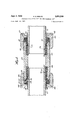
Fig. 4 is an axial sectional view of an insulating lock pipe coupling constructed in accordance with the invention;
Fig. 5 -is a similar view of an insulating lock T coupling constructed in accordance with the invention;
Fig. 6 is a cross-sectional view of a modified form of the coupling shown in Fig. 4; and
, Fig. 7 is an eleyational view, partly in section, illusr t n t embo imen o h in n.
Referring to the drawings, and more particularly to Figs- 1 m3, the e e e e numera 0 designates gen n ally a pipe coupling in the nature of an adapter constructed in accordance with the invention and adapted primarily for connecting a gas meterin a gas distribution system. As shown in Fig. 1, a gas meter 12, having an inlet pipe '13 and an outlet pipe 14, is connected in the, gas flow line provided by the supply pipe 15 and the distribution pipe 16, by means of fittings 10 which connect the supply pipe tothe inlet pipe 13 and connect the distribution pipe 16 to the outlet pipe 14. Referring to Figs. 2 and 3, the coupling or adapter 10 has a sleeve body 20 which has an enlarged end 22 formed with a threaded pipe-receiving aperture 24. f The aperture 24 communicates with an enlarged non-threaded chamber 25 defined interiorly of the other end of body 20 which is of reduced external diameter and increased internal diameter. Exteriorly, the latter end is formed with a cylindrical portion 25 extending from the outer edge 27 of the body to a raised annular section 28, the outer surface of which is provided with threads 29. From the edge 27, the body tapers inwardly to define a gasket recess 31. V
Fluid-tight sealing engagement between the body 20 and the ends of the pipe to be joined, e. g..pipe 15 or 16, is effected by compression of a gasket which is adaptedto be received in the gasket recess 31 and which, in the embodiment illustrated, is annular in formand separately. The gasket 35 and the sleeve are formed from rubber or rubber composition, this term being used generically to include natural and synthetic rubbers and other elastomeric compounds, or compositions having like properties and characteristics. The material is relatively firm and solid but sufficiently resilient and elastic tofiow under pressure to conform to the surfaces between which it is confined. Advantageously gasket 35 is formed from a rubbery composition which is relatively resistant to attack by hydrocarbon gases and oils. Examples of such resistant rubber compositions suitable for use in the coupling of the invention are butadiene-acrylonitrile copolymers, such as those known commercially by the trade designations BunaN or GR-A. The gasket'is not limited to these specific materials, however, and particularly when special resistance to hydrocarbon gases and oils is not required, any rubbery composition having the abovenoted characteristics may be employed.
gasket retainer takes the form of a cup-shaped annular member 52 conveniently stamped or otherwise formed from a metal sheet to define a body portion 53 formed with an aperture 55 sufficiently large to receive pipe 15 and sleeve 38 and a peripheral flange 56 which is dimensioned to be received by the cylindrical portion 26. In the adapter illustrated, the follower nut 46 is formed with apertured ears or projections 53 adapted to receive sealing wires to permit attachment of the usual utility company seal on the meter installation.
Positioned within coupling body 20 and disposed in chamber 25 is an annular insulating sleeve member or collar 60 which is shaped to conform to the inner surface of the chamber 25 and is adapted to receive the end of the pipe. For this purpose, as shown in Fig. 2, the insulating member 60 is internally threaded as indicated at 62 over the major portion of its length but has an unthreaded portion 64. The member 60 threadedly engages the forward end of pipe 15 but the unthreaded portion 64 prevents the pipe from passing entirely through member 60. As a result, the unthreaded portion 64 serves as an insulating extension of the pipe and effectively prevents. all electrically conductive contact between the pipe and the coupling body. As shown in the drawing, the external diameter of the member 69 is greater than the diameter of pipe aperture 44 in follower nut 43 with the result that once the follower nut is engaged with the coupling body, the pipe 15 cannot be axially pulled.
out of the coupling. Not only does the gasket 35 resist outward movement of the pipe by reason of its engagement with the member 60 but the member 60 will me ously formed from a relatively rigid insulating plastic material such as polystyrene, a phenol-formaldehyde resin, a urea-formaldehyde resin, and the like. The member 69 is conveniently formed from such materials by conventional molding techniques. The member 60 may, however, be formed from a less rigid insulating material, for example, a synthetic elastomeric compound or composition such as neoprene (polychloroprene) or other compounds or compositions having like properties and characteristics. However, the insulating member 60 is thus formed from a material which is substantially more resistant to deformation than the material used in forming the gasket 35.
By means of the insulating adapter it is possible to install a gas meter rapidly and efiiciently in a manner which protects it and the pipe line connected to it from the damaging action of stray electrical currents. To make the installation shown in Fig. 1, for example, the adapter sleeve bodies are screwed to the meter inlet pipe 13 and outlet pipe 14. The follower nuts 40, the retainers 5?. and the gaskets 35 are slipped over the ends of the supply pipe 15 and the distribution pipe 16, the insulating members 60 are screwed on to the ends of these pipes, and the meter with the sleeve bodies is then brought into position to permit threaded engagement of the follower nuts with the sleeve bodies.
The two pipe sections of the meter installation are thus connected in fluid-tight, flexibly-locked, non-conducting relationship. In Fig. l the meter installation illustrated errnloys two adapters 10. However, one of the adapters 10 will sufiice to prevent flow of electric current through the meter, and the other adapter could, if desired, be replaced by one of conventional non-insulating construction. From the standpoint of ease of installation and of effective locking against axial thrusts, however, it is preferable to use both of the adapters 10. The adapters 10 may, if desired, be inverted, i. e. with the supply and distribution pipes threadedly engaged in the aperture 24 and with the meter pipes in engagement with the insulating members 60 and the gaskets 35. Further, while the adapter 19 has been shown in a meter installation, its usefulness is not limited to such arrangements and it may be used wherever an insulating, locking joint between two pipes is desired, particularly when strong axial thrusts will be encountered.
Regardless of the type of installation, the adapter 10 will effectively resist removal of the pipes when in service while efi'ectively maintaining its sealing and insulating action. In the event of inward axial stress on the pipes, the insulating member 64} will be forced against the end of the chamber 25 which is the shoulder 61 defined by the internally-threaded portion of the body 20 and at all times electrically-conductive engagement between the pipes 15 and 16 and the bodies of the corresponding adapters will be prevented, so that flow of current through the meter and through the line in which the meter is placed is avoided. Upon axial stress on the pipes in the adapters 10, the insulating member 6% will be drawn toward the follower nut 40. However, at the same time the gasket will be given an axial thrust which will resist further outward movement of the member 69 and the pipe upon which it is mounted. At the same time the axial thrust will increase the sealing pressure of the gasket on the pipe and escape of gas will be prevented.
The invention is, however, not limited to an adapter couplin as shown in Figs. 1 to 3 but may be embodied in insulating saddles, couplings and fittings of other types for interconnecting two or more pipes. In Fig. 4, wherein parts corresponding to those shown in Figs. 1 to 3 have been given like reference numerals to which 100 has been added, there is shown a coupling of the type in which two colinearly-disposed pipes are connected without threaded engagement therewith. In Fig. 4, the reference numeral 129 designates the sleeve body or middle ring f the coupling illustrated which is in the form of a tubular sleeve having symmetrical ends. Each end of sleeve 12% like the smaller end of adapter 20, has an exterior surfacedefined by a cylindrical portion 12s extending from the uoter edge 127 to a raised threaded annular section 128.
lnteriorly, the ends of sleeve 12% taper inwardly from the edges 127 to define gasket recesses 131 which communicate with the interior chamber 125. Seated in gasket recesses 131 are gaskets 135, formed from the matesial used for gasket 35, as above described. Each gasket 135 has a main body portion 136 and a sleeve portion 138 adapted to embrace the pipe and extending outwardly along the pipe surface beyond the end of sleeve 12!). Gasket sealing is effected by means of retainers 15.2 and follower nuts 140, substantially identical in construction to retainer 52 and follower nut ll} except that the cars 58 are not provided in this embodiment. Positioned within the chamber are annular insulating members 160, each threadedly engaging one of the pipes 115, with the unthreaded portions 164 of the members in opposed relationship. The insulating members 160 are substantially identical in form and material of construction to the insulating member 6% above described, and have an external diameter which is greater than the diameter of the pipe apertures 144 in the follower nuts Lt iil. The relationship of parts in such as shown that the gaskets disposed adjacent the members tee and outward axial movement of either of the pipes causes the members 169 to exert an axial thrust on the gaskets to increase their sealing action.
The coupling 110 when installed on the ends of the pipes 115 thus provides an insulating, locking, flexible connection between the pipes. By reason of the flexibility of the joint, shocks and vibrations are absorbed while the fluid-tightness and insulating efiectiveness of the joint are maintained at all times.
In order to insure against removal of the pipe from the fitting when the lock wire is in position, there may be advantageously provided locking means for preventing rotation of the pipe without concurrent rotation of the insulating member. Examples of such locking means are shown in the coupling of Fig. 4 but it will be apparent that these locking means are equally applicable to the other embodiments illustrated and to other fittings in which the invention may be embodied. As shown in Fig. 4, an insulating washer 1'75, e. g. a fibre washer, is positioned around the pipe between the toe of the gasket and the axially outer face of the insulating member 1659. The Washer 175 prevents the gasket from holding the insulating member res against rotation when the pipe is rotated. Ordinarily, frictional contact with the gasket may be sufiicient to hold the member ltd-ll against rotation and thereby permit the pipe to be unscrewed out of it. Another locking means for the insulating member 161] which may be used independently of or in combination with the washer 175 is also shown in Fig. 4. This means comprises an insulating pin 176 formed from fibre or other like rigid insulating material. The pin is passed through an aperture 177 drilled in the insulating member Edit and in the pipe Wall. When the pin locking means is employed, the insulaing member is first screwed on the end or" the pipe, then an aperture 177 is drilled through the member and the pipe and the insulating pin 176 inserted. The pipe with the member thus attached is then inserted in the fitting end and the gasket and follower nut drawn up as previously described.
In accordance with another embodiment of the invention, means are provided for preventing application of the gasket pressure to the insulating members and thereby to prevent the gaskets from holding the members from rotation with their respective pipe sections. Such an embodiment, in the form of a I, is shown in Fig. 5, wherein parts corresponding to those shown in Figs. 1 to 3 have been given the same reference numerals to which 209 223 which are adapted to receive the pipes to be interconnected, the branch 223 extending from the body 220 substantially centrally thereof. are provided with cooperating retainers 252, follower nuts 240, and gaskets 235. Interiortly the middle ring 220 defines chambers 225 and is formed with annular ribs 222 which provide shoulders 261 against which the insulating members 260 will engage to resist inward axial thrusts. Axially outwardly of chambers 225 the internal diameter is increased to define shoulders 262 and insulating Washers 275, similar in construction to washers 175 shown in Fig. 4, are dimensioned to engage these shoulders. When pressure is applied to the gaskets, they are driven against the washers 275, which are held against inward axial movement by the shoulder 262 and thus the gaskets do not apply pressure to the members 260 which are free to rotate with the pipes. Like the fittings shown in Figs. 1 to4 the T 218 provides an electrically-insulating, positively-locking, flexible connection among the 322 defining shoulders 361 and chambers 325 wherein are seated the insulating members 360 which surround the ends of the pipes 315. The ends of middle ring 321) are provided with retainers 352, nuts 340 and gaskets 335. Resisting the inward thrust of the gaskets and shielding the insulating members 360 are pressure resisting elements 365 which have a radial wall portion 366 engaging the toe of the adjacent gasket 335 and an axial flange portion 367 which has a greater length than the insulating member 368 and engages the shoulder 361. The elements 365 are formed from any convenient insulating material.
It will be apparent that the invention may be embodied in pipe fittings other than those described above. In Fig. 7, for example, there is shown a saddle provided with aninsulati ng pipe connector constructed in accordance with the invention. The saddle comprises an arcuate body plate 470 secured to the pipe by means of U-bo1ts 471 which. pass through apertures 472 in the body plate and are secured by nuts 473. A gasket 475 seals the joint between thea perture 476 in the pipe and the central bore 477 of the body plate. Threadedly engaged in the bore 477 is the connector 428 having an externally threaded inner end portion 422 and an outer end portion defining a chamber 425 ending in the shoulder 461. As in the embodiment of Fig. 2, connector 420 is provided with a retainer 452, a follower out 440 anda gasket 435. Seated in the chamber 425 and surrounding the pipe 415 is the insulating member 461 By use of the connector 42% the pipe 415 is electrically insulated from the main line pipe upon which the saddle is mounted. Instead of being a removable element, the connector 420 may be formed integrally with the saddle body plate to provide a unitary fitting for joining a branch line to a main line in electrically non-conducting relationship.
It will be apparent to those skilled in the art that various changes and modifications may be made in the em- The branches and the T 8 bodiments described and illustrated without departing from the scope of the invention as defined in the appended claims. It will further be, understood that, insofar as they are not rnutualy incompatible, the various features and details of construction of the several embodiments shown and described are interchangeable withoneanother. It is intended, therefore, that all matter contained in the foregoing description and in the drawing shall be interpreted as illustrativeonly and not as limitative of the invention.
What I claim and desire 1. An insulating pipe fitting adapted to receive the end of a threaded pipe and to hold said pipe in flexible fluidtight relationship but with the pipe locked in said fitting against excessive outward axial movement comprising, in combination, a tubular body having at least one end deto secure by Letters Patent fining a pipe-receiving opening, said body forming a extending into said chamber, nut means engageable with said body to apply pressure to said resilient. gasket to cause said gasket to engage said pipe and said recess in flexible yet sealing relationship, said nut means having a central pipe-receiving aperture and the diameter of said chamber being greater than the diameter of said aperture,
insulating sleeve means extending axially-outwardly from said gasket and adapted to overlie said pipe and to pass through saidpipe-receiving,aperture with a clearance between the sleeve means and the surface of said nut means adjacent said aperture to prevent electrically-conductive contact between the pipe and said nut means, a tubular sleeve member ofhardinsulatingmaterial disposed in said chamber with a clearance between the outer surface of said member and said cylindrical wall surface,-said sleeve member being internally threaded for threaded engagement withthe end of said threaded pipe, said sleeve member being colinear with said gasket and in lateral engagement with the forward portion of said gasket extending into said chamber, whereby outward axial movement of said sleeve member will exert a lateral thrust upon said gasket, the external diameter of said hard insulating sleeve member being greater than the diameter of said aperture in said nutlmeans, and means to resist extrusion of said gasket through said aperture.
2. An insulating pipe fitting as defined in claim 1, wherein said body has a threaded end for threaded connection with a second pipe.
References Cited in the file of this patent UNITED STATES PATENTS
Priority Applications (1)
| Application Number | Priority Date | Filing Date | Title |
|---|---|---|---|
| US381704A US2850299A (en) | 1953-09-22 | 1953-09-22 | Flexible insulating coupling for threaded pipe |
Applications Claiming Priority (1)
| Application Number | Priority Date | Filing Date | Title |
|---|---|---|---|
| US381704A US2850299A (en) | 1953-09-22 | 1953-09-22 | Flexible insulating coupling for threaded pipe |
Publications (1)
| Publication Number | Publication Date |
|---|---|
| US2850299A true US2850299A (en) | 1958-09-02 |
Family
ID=23506064
Family Applications (1)
| Application Number | Title | Priority Date | Filing Date |
|---|---|---|---|
| US381704A Expired - Lifetime US2850299A (en) | 1953-09-22 | 1953-09-22 | Flexible insulating coupling for threaded pipe |
Country Status (1)
| Country | Link |
|---|---|
| US (1) | US2850299A (en) |
Cited By (16)
| Publication number | Priority date | Publication date | Assignee | Title |
|---|---|---|---|---|
| US2950928A (en) * | 1957-12-17 | 1960-08-30 | Mueller Co | Insulated pipe joint |
| US3061665A (en) * | 1958-07-31 | 1962-10-30 | Westinghouse Electric Corp | Electrical bus structure |
| FR2181682A1 (en) * | 1972-04-24 | 1973-12-07 | Schwarz Walter | |
| US3796446A (en) * | 1971-12-10 | 1974-03-12 | Gen Connector Corp | Connector |
| US3807773A (en) * | 1971-12-02 | 1974-04-30 | H Brune | Conduit union and gasket |
| FR2551830A1 (en) * | 1983-09-08 | 1985-03-15 | Imp Clevite Inc | HIGH-PRESSURE TUBE CONNECTION, SEALED AND ANTI-CURING |
| US4646775A (en) * | 1983-11-03 | 1987-03-03 | Traylor Paul L | Vacuum breaker |
| US5056755A (en) * | 1990-07-26 | 1991-10-15 | Jang Young H | Gate valve |
| US6422609B1 (en) | 1999-08-20 | 2002-07-23 | Itt Manufacturing Enterprises, Inc. | Fluid joint |
| US6767001B2 (en) * | 2002-07-02 | 2004-07-27 | Anderson Brass Company | Adjustable manifold joining system |
| US20050104371A1 (en) * | 2003-11-19 | 2005-05-19 | Atkinson Manuel D. | Quick connect and quick disconnect plumbing apparatus |
| US7267375B1 (en) * | 2004-10-25 | 2007-09-11 | Sorkin Felix L | Duct coupler apparatus |
| US11098828B2 (en) * | 2018-12-07 | 2021-08-24 | The Boeing Company | Apparatus and methods for connecting a first electrically conductive tube and a second electrically conductive tube |
| US11274779B2 (en) * | 2019-02-21 | 2022-03-15 | Legend Valve & Fitting, Inc. | Dielectric fitting |
| US11309696B2 (en) * | 2019-05-08 | 2022-04-19 | Inspur Suzhou Intelligent Technology Co., Ltd | Cable carrier apparatus with power supply function |
| US11515694B2 (en) * | 2017-11-28 | 2022-11-29 | Subsea Energy Solutions Ltd | Stiffening member and protective housing assembly |
Citations (10)
| Publication number | Priority date | Publication date | Assignee | Title |
|---|---|---|---|---|
| US476188A (en) * | 1892-05-31 | Iialp to allen j | ||
| US602564A (en) * | 1898-04-19 | Insulated pipe-coupling | ||
| US646742A (en) * | 1899-12-15 | 1900-04-03 | Adolphus A Knudson | Electric bond for street-mains. |
| US718826A (en) * | 1900-01-30 | 1903-01-20 | Harry C Dick | Gas-meter. |
| FR616577A (en) * | 1925-10-09 | 1927-02-04 | Pipe connection | |
| US1678955A (en) * | 1926-11-23 | 1928-07-31 | Rockenbauer Otto | Tampering-indicating device for gas meters |
| US2211776A (en) * | 1937-08-02 | 1940-08-20 | George W Haury | Resilient coupling for tubing and method for making the same |
| US2269695A (en) * | 1941-04-04 | 1942-01-13 | Dresser Mfg Company | Insulating coupling |
| US2278479A (en) * | 1939-12-09 | 1942-04-07 | Arthur L Parker | Tube coupling |
| FR891167A (en) * | 1942-09-09 | 1944-02-29 | Improvements to pipe fittings |
-
1953
- 1953-09-22 US US381704A patent/US2850299A/en not_active Expired - Lifetime
Patent Citations (10)
| Publication number | Priority date | Publication date | Assignee | Title |
|---|---|---|---|---|
| US476188A (en) * | 1892-05-31 | Iialp to allen j | ||
| US602564A (en) * | 1898-04-19 | Insulated pipe-coupling | ||
| US646742A (en) * | 1899-12-15 | 1900-04-03 | Adolphus A Knudson | Electric bond for street-mains. |
| US718826A (en) * | 1900-01-30 | 1903-01-20 | Harry C Dick | Gas-meter. |
| FR616577A (en) * | 1925-10-09 | 1927-02-04 | Pipe connection | |
| US1678955A (en) * | 1926-11-23 | 1928-07-31 | Rockenbauer Otto | Tampering-indicating device for gas meters |
| US2211776A (en) * | 1937-08-02 | 1940-08-20 | George W Haury | Resilient coupling for tubing and method for making the same |
| US2278479A (en) * | 1939-12-09 | 1942-04-07 | Arthur L Parker | Tube coupling |
| US2269695A (en) * | 1941-04-04 | 1942-01-13 | Dresser Mfg Company | Insulating coupling |
| FR891167A (en) * | 1942-09-09 | 1944-02-29 | Improvements to pipe fittings |
Cited By (18)
| Publication number | Priority date | Publication date | Assignee | Title |
|---|---|---|---|---|
| US2950928A (en) * | 1957-12-17 | 1960-08-30 | Mueller Co | Insulated pipe joint |
| US3061665A (en) * | 1958-07-31 | 1962-10-30 | Westinghouse Electric Corp | Electrical bus structure |
| US3807773A (en) * | 1971-12-02 | 1974-04-30 | H Brune | Conduit union and gasket |
| US3796446A (en) * | 1971-12-10 | 1974-03-12 | Gen Connector Corp | Connector |
| FR2181682A1 (en) * | 1972-04-24 | 1973-12-07 | Schwarz Walter | |
| FR2551830A1 (en) * | 1983-09-08 | 1985-03-15 | Imp Clevite Inc | HIGH-PRESSURE TUBE CONNECTION, SEALED AND ANTI-CURING |
| US4538842A (en) * | 1983-09-08 | 1985-09-03 | Imperial Clevite Inc. | High pressure, leakproof, blowout-proof tube fitting |
| US4646775A (en) * | 1983-11-03 | 1987-03-03 | Traylor Paul L | Vacuum breaker |
| US5056755A (en) * | 1990-07-26 | 1991-10-15 | Jang Young H | Gate valve |
| US6422609B1 (en) | 1999-08-20 | 2002-07-23 | Itt Manufacturing Enterprises, Inc. | Fluid joint |
| US6767001B2 (en) * | 2002-07-02 | 2004-07-27 | Anderson Brass Company | Adjustable manifold joining system |
| US20050104371A1 (en) * | 2003-11-19 | 2005-05-19 | Atkinson Manuel D. | Quick connect and quick disconnect plumbing apparatus |
| US7156425B2 (en) * | 2003-11-19 | 2007-01-02 | Manuel Diaz Atkinson | Quick connect and quick disconnect plumbing apparatus |
| US7267375B1 (en) * | 2004-10-25 | 2007-09-11 | Sorkin Felix L | Duct coupler apparatus |
| US11515694B2 (en) * | 2017-11-28 | 2022-11-29 | Subsea Energy Solutions Ltd | Stiffening member and protective housing assembly |
| US11098828B2 (en) * | 2018-12-07 | 2021-08-24 | The Boeing Company | Apparatus and methods for connecting a first electrically conductive tube and a second electrically conductive tube |
| US11274779B2 (en) * | 2019-02-21 | 2022-03-15 | Legend Valve & Fitting, Inc. | Dielectric fitting |
| US11309696B2 (en) * | 2019-05-08 | 2022-04-19 | Inspur Suzhou Intelligent Technology Co., Ltd | Cable carrier apparatus with power supply function |
Similar Documents
| Publication | Publication Date | Title |
|---|---|---|
| US2850299A (en) | Flexible insulating coupling for threaded pipe | |
| US2669465A (en) | Insulating coupling | |
| US2790652A (en) | Insulated saddle type pipe fitting | |
| US3507506A (en) | Pipe joint seal | |
| US4158461A (en) | Pipe tapping bands | |
| US2919147A (en) | Adjustable, lockable male threaded fitting and seal therefor | |
| US2456234A (en) | Bolt protector | |
| US4595218A (en) | Insulative coupling | |
| US3036601A (en) | Terminal extension fitting | |
| US2318575A (en) | Pipe coupling | |
| US2569333A (en) | Insulated union nipple | |
| US2148036A (en) | Standard adapter joint for connecting tubing | |
| US2758852A (en) | Coupling for threadless pipe with independent sealing and gripping means | |
| US2784933A (en) | Service tau | |
| US2201862A (en) | Pipe coupling | |
| USRE25047E (en) | E risley | |
| US11320074B2 (en) | No contact connectors | |
| US3328053A (en) | Insulated pipe joint | |
| US2286566A (en) | Pipe connection | |
| US2108848A (en) | Pipe joint | |
| US3517950A (en) | Insulating pipe union | |
| US9982819B2 (en) | Tube seal assembly | |
| US2518829A (en) | Pressure sealing member | |
| CN205371878U (en) | Stainless steel pipe connecting piece | |
| US3257118A (en) | Pipe repair joint |