US2850171A - Shelf-type display rack - Google Patents
Shelf-type display rack Download PDFInfo
- Publication number
- US2850171A US2850171A US348474A US34847453A US2850171A US 2850171 A US2850171 A US 2850171A US 348474 A US348474 A US 348474A US 34847453 A US34847453 A US 34847453A US 2850171 A US2850171 A US 2850171A
- Authority
- US
- United States
- Prior art keywords
- base
- beams
- shelf
- construction
- frame
- Prior art date
- Legal status (The legal status is an assumption and is not a legal conclusion. Google has not performed a legal analysis and makes no representation as to the accuracy of the status listed.)
- Expired - Lifetime
Links
- 238000010276 construction Methods 0.000 description 22
- 125000006850 spacer group Chemical group 0.000 description 9
- 230000008878 coupling Effects 0.000 description 5
- 238000010168 coupling process Methods 0.000 description 5
- 238000005859 coupling reaction Methods 0.000 description 5
- 240000001973 Ficus microcarpa Species 0.000 description 1
- 101000583057 Homo sapiens NGFI-A-binding protein 2 Proteins 0.000 description 1
- 102100030391 NGFI-A-binding protein 2 Human genes 0.000 description 1
- 241000607479 Yersinia pestis Species 0.000 description 1
- 238000004873 anchoring Methods 0.000 description 1
- 239000000969 carrier Substances 0.000 description 1
- 230000004048 modification Effects 0.000 description 1
- 238000012986 modification Methods 0.000 description 1
- 230000000284 resting effect Effects 0.000 description 1
- 239000002023 wood Substances 0.000 description 1
Images
Classifications
-
- A—HUMAN NECESSITIES
- A47—FURNITURE; DOMESTIC ARTICLES OR APPLIANCES; COFFEE MILLS; SPICE MILLS; SUCTION CLEANERS IN GENERAL
- A47F—SPECIAL FURNITURE, FITTINGS, OR ACCESSORIES FOR SHOPS, STOREHOUSES, BARS, RESTAURANTS OR THE LIKE; PAYING COUNTERS
- A47F5/00—Show stands, hangers, or shelves characterised by their constructional features
- A47F5/10—Adjustable or foldable or dismountable display stands
- A47F5/101—Display racks with slotted uprights
- A47F5/103—Display shelving racks with the uprights aligned in only one plane
Definitions
- Display racks involving or characterized by one or more shelves are employed in stores and in various places where articles are to be stored or exhibited. Structures of this type ordinarily employed as, for instance, in stores where merchandise is displayed are of somewhat complicated construction if they are so built as to be stable and durable or they are, in most cases, flimsy if they are of light construction. Racks such as are referred to are of the type that in some instances are set on the oor while in other cases they are set on counters, cabinets or other supports.
- Another object of this invention is to provide a structure of the type mentioned having a simple, practical, improved base characterized by means for effecting adjustment so that the base can be adjusted to a level position and having atop which, when in place, completely covers the balance of the structure, which top is removable to provide access to the structure that occurs beneath it.
- Another object of the invention is to provide a display rack of the general character referred to characterized by a releasable coupling means connecting the base and back, which means is such as to provide for simple, quick connection or coupling of the base and back and is such as to effectively and rigidly clamp or tie the back to the base when it is fully engaged.
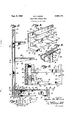
- Fig. l is a perspective view of embodiments of the invention, that is, of display racks, provided by the invention showing them arranged end to end in which position they may be coupled if desired.
- Fig. 2 is an enlarged, vertical, transverse sectional view of the structure provided by the present invention, being a view taken substantially as indicated by line 2 2 on Fig. l.
- Fig. 3 is a plane section taken substantially as indicated by line 3-3 on Fig. 2 with the cover removed.
- Fig. 4 is a 2,85@,l7l Patented Sept. 2, 1958 "ine perspective view of a portion of the structure showing parts in section and illustrating a rail provided to carry a shelf bracket and showing the manner in which the rail is related to the back
- Fig. 5 is a vertical, sectional view of structure such as is shown in Fig. 4, showing a shelf bracket engaged with the rail that is shown in Fig. 4.
- the fixture or rack provided by the present invention is preferably in the nature of a unit including generally a base A, a back B, means C releasably connecting the base and the back, shelves D, brackets E carrying the shelves D and means F adjustably coupling the brackets E to the back B.
- the base A of the structure is in the nature of a flat elongate platform having a horizontally disposed rectangular frame 10 and a top or cover 11 carried by frame 10.
- the frame 10 of base A is formed of or by a front elongate beam 12, a rear elongate beam 13, and end beams 14 that extend between and connect the ends of the beams 12 and 13.
- the elements 12, 13 and 14 are preferably formed of wood and, in practice, any suitable construction may be employed to establish fixed permanent joints between the ends of the beams 12 and 13 and the end beams 1li.
- the frame 10 includes spreaders 15, spaced apart between the end beams 14 and extending between the front and rear beams 12 and 13.
- the spreaders 15 are parallel with the end beams 14 and have the ends set or mortised into sockets 16 provided in the opposed sides of the beam 12 and 13.
- the spreaders 15 are located at the end portions of the structure as a whole so that they are spaced somewhat inward from the end beams 1d and they are employed as carriers for feet 20.
- each spreader 15 is shown as carrying two feet and each foot is mounted by means of a threaded stem 21 carrying the foot and having threaded engagement with a block Z2 rigidly carried by a spreader.
- the several feet 20 employed in the structure are individually adjustable, and they can be readily adjusted to bring the baseinto the desired firm engagement with a support such as a floor or any other structure employed as a mounting.
- the several beams 12, 13 and 14 of frame 1l have top faces 25 that are flat and which are flush.
- a rib'26 is provided at the forward side of the front beam 12 and projects somewhat above the face 25 of beam 12 as is shown in Fig. 2 of the drawings.
- ribs 27 are provided on the end beams 14 adjacent their outer sides 28 and project upward from the faces 25 of the beams 14 in the same manner that the rib 26 projects above the beam 12.
- the top 1l. of the base A is preferably a simple, flat rectangular unit and it may, as shown in the drawings, be of uniform thickness throughout.
- the top 12 is shaped and proportioned to rest on the top faces 25 of the beams 12, 13 and 14 While being confined by or held within the ribs 26 and 27 as shown in the drawings. ln practice, the top 11 is preferably a unit, loose relative to base 10, and when it is in use it simply rests upon the faces 2S of the beams 12, 13 and 14.
- the back B of the structure is a ilat rectangular unit, and in the preferred construction, it is made up or includes a horizontal bottom sill 36, a horizontal header 31, and uprights or posts 32 at the ends of the back and extending vertically between the ends of the sill 30 and header 31.
- the elements 30, 31 and 32 are, in practice, rigidly and permanently connected together at the corners of the back, and, in practice, any suitable construction can be employed at these joints.
- the back includes, in addition to the frame made up of the members 30, 31 and 32, panels 36 and 37.
- the panel 36 is a front cover carried by and occupying the front of the frame made up of the elements30, 31 and 32.
- the panel 37 is a back panel covering the back of the frame made up of the elements 30, 31 and 32.
- a spacer 40 isf provided on or carried by the sill at the one side thereof and projects up from the bottom of the sill to a point hush with the faces 25 of the beams of frame 10. In this case the top or upper edge 41 of the sill 30 occurs a substantial distance above the top of the spacer' 40.
- the front panel 36 in the case under consideration, rests on the upper edge of beam 13 and extends to the top of the header 31 and to the outermost edges of the pests 32.
- the top 47 of the spacer 40 is disposed in the plane of faces 25 of the frame.
- the back panel 37 seats on the top of spacer and extends up to the top of header'31 and to the outer edges of the posts 32.
- the spacer 40 can be made readily removable and by arranging it at one side or the other of the sill 30 the back can be reversed side for side or if the spacer 4G is removed bases can be engaged with the back from each side thereof.
- binding members or trimmers 50 may be provided at the vertical ends of the back while a horizontal trimmer 51 is provided at the top of the back.
- the coupling means C provided by the present invention serves to releasably connect or tie the lower edge portions of the back B to the rear edge portion of the base A and to the end beams respectively of the frame.
- the two units of the means C are located at the end portions of the structure.
- the two units of means C are preferably alike and each includes a bolt carried by the back B at the lower edge portion thereof to project forward therefrom through an opening 61 provided for that purpose in the rear beam 13 of the frame 10 of base A.
- a brace 62 is carried by the frame 1i) and receives the bolt, and a nut 63 is threaded on the bolt and clamps against the brace.
- the bolt 6i) passes through the sill 30 and the spacer 40 of back B, the head of the bolt being under and covered by the spacer 40 secured to the rear side of the sill 30
- the brace 62 that receives the bolt and which is engaged by the nut is preferably a metallic unit and is preferably L-shaped in form having a flange 66 engaged with and secured at against the inner side of an end beam 14 and having a flange 67 engaged against the forward side of the rear beam 13.
- the flanges of brace 62 may, in practice, be secured to the beams of frame 10 by suitable fasteners as, for instance, by screw fasteners 69, or the like.
- the flange 66 of brace 62 has a lip 70 formed thereon and projecting therefrom to enter a suitable notch in the end beam 14 thus anchoring or tying the end beam to the rear beam.
- the flange 67 of brace 62 has an opening that passes the bolt 60, and the nut 63 is preferably a wing nut threaded on the bolt 60 and bearing against the forward side or face of flange 67.
- the back B is easily positioned relative to base A by simply entering the bolts 60 that project forward from the back through the openings 61 in the rear beam of the base.
- Flange 67 is preferably formed with a lip 70 projecting into a notch in beam 13 as shown in Fig. 3.
- the nuts 63 may be engaged with the bolts and made tight so that the engaged parts are rmly and effectively ⁇ clamped together.
- the top 11 of the base A can be removed whenever it is desired either to apply or to release the nuts 63 of the means C, and this is also true relative to the feet 20 which may require adjustment from time to time.
- one or more shelves D may be provided, and where there is more than one shelf, the shelves may vary in width as shown in the drawings. It is preferred, in practice, that the back B be exactly equal in length to the base A, and likewise it is preferred that the shelves D be of the same length as shown in the drawings.
- brackets E provided for carrying the shelves D may, in practice, vary widely in form and construction and for purposes of example, the brackets are shown as simple or conventional brackets designed to carry the shelves so that they are horizontally disposed.
- each bracket as shown has an elongate member having a flat rear end adapted to oppose the back B and provided at its forward terminal end with a hook portion 81 adapted to engage and hold a shelf.
- the number of brackets for each shelf may vary although for most cases two brackets are sufficient as shown in the drawings.
- the means F provided to releasably and adjustably couple the brackets to the back, is shown as including rails carried by the back and adapted to receive hooks 91 provided on the brackets E.
- the rails 90 are vertically disposed and where there is to be two brackets E for each shelf, there are two rails suitably spaced inward from the ends of the back B.
- the rails 90 are carried by cores 92 located in the back B to occur between the panels 36 and 37 of the back B, and the front panel 36 is provided with vertical openings that receive or would serve to accommodate the rails as clearly illustrated in Fig. 4 of the drawings.
- each rail 90 is an elongate member U-shaped in cross sectional configuration to have a front 95 which is fiat and flush with the forward face of the front panel 36.
- the sides 96 of the rail are parallel, extending rearwardly from the front 95 to the core 92 which is a wide vertically disposed frame-like element held tightly between the panels 36 and 37.
- Flanges 97 on the sides 96 set against the core 92 and suitable fasteners, such as screws 98, secure the anges to the core.
- the front 95 of the rail has a series of openings.
- brackets 98 adapted to accommodate the hooks 91 that project rearward from the ends 80 of the brackets.
- the brackets can be adjusted or set in various positions lengthwise of the rails to locate the shelves D as desired.
- the present invention provides a construction in the form of a unit including a base A, back B, shelves D, etc., and this unit can be alone or independently as desired or, as shown in Fig. l, be used in connection with another or an adjacent unit and such other unit may be the same as that provided by the invention or it may differ as the circumstances may require.
- this unit can be alone or independently as desired or, as shown in Fig. l, be used in connection with another or an adjacent unit and such other unit may be the same as that provided by the invention or it may differ as the circumstances may require.
- the base A thereof is of plain, smooth, simple form and is of inexpensive yet sturdy stable construction.
- the back B thereof is of simple, inexpensive construction, is pleasing in appearance and is likewise rigid and sturdy.
- the means C that releasably couples the back and base is a very simple yet effective means effectively securing these parts together and is a means that is readily accessible .by reason of the removable cover. 11
- a rack having a back, a base and shelves, the back being releasably secured to the base and the shelves being mounted on the back and disposed above the base, the combination with said back and base of means for tying the back to the base with tying force being exerted directly to points in the base spaced substantially forwardly of the back, said base comprising a horizontally dispose-d rectangular frame having elongate front and rear beams and end beams fixed to and extended between respective ends of the front and rear beams whereby the rear beam and end beams dene two inside corners in the rear portion of the frame, the base further comprising a cover resting on top of said beams and spaced slightly inwardly from the outside upper edges of the front and end beams, the back being disposed vertically with respect to the base and having a front surface, the lower horizontal marginal portion of which is abutted flush against the rear surface of said rear beam, a pair of bolts secured in'the back and extending forwardly beyond the plane of said front surface and proximate respective end
- each brace having a rear-beam-abutting flange and an end-beam-abutting flange, the end-bearn-abutting ange of each brace having a lip formed in the forwardly disposed end thereof andv engaged in a notch formed on the inside surface of its respective end beam, the rear beam and the rear-beam-abutting flange of the brace having aligned openings formed therein for receiving the bolt, the bolt extending through said aligned openings, and a nut screw-threaded on the forwardly disposed end of the bolt and turned tight against the forwardly facing surface of the rear-beam-abutting flange of the brace, thereby to transmit the tying force of the bolts through the rear beam and said brace lips and to the end beams, respectively.
Landscapes
- Assembled Shelves (AREA)
Description
Sept. 2, 1958 M. H. MADER SHELF-TYPE DISPLAY RACK Filed April 1s, 195s wam MAer//v Lf. M Home,
IN VENTOR 4 Trae/EY- United States Patent SHELF-TYPE DSPLAY RACK Martin H. Mader, Los Angeles, Calif., assignor to Mader Cabinet Works, lne., Los Angeles, Calif., a corporation of California Application April 13, 1953, Serial No. 348,474
1 Claim. (Cl. 211-141) This invention has to do with a shelf-type display rack, and it is a general object ofthe invention to provide a simple, practical, improved structure of this character.
Display racks involving or characterized by one or more shelves are employed in stores and in various places where articles are to be stored or exhibited. Structures of this type ordinarily employed as, for instance, in stores where merchandise is displayed are of somewhat complicated construction if they are so built as to be stable and durable or they are, in most cases, flimsy if they are of light construction. Racks such as are referred to are of the type that in some instances are set on the oor while in other cases they are set on counters, cabinets or other supports.
It is a general object of this invention to provide a shelf-type display rack characterized by a flat, horizontally disposed base and a flat vertically disposed back, which elements are releasably coupled so that the back is effectively maintained in vertical position and serves as an effective mounting or carrier for shelves secured to the back to project forward therefrom so that they overlie the base.
Another object of this invention is to provide a structure of the type mentioned having a simple, practical, improved base characterized by means for effecting adjustment so that the base can be adjusted to a level position and having atop which, when in place, completely covers the balance of the structure, which top is removable to provide access to the structure that occurs beneath it.
It is another object of this invention to provide a rack of the general character referred to including a back in the form of a flat vertical unit characterized by a frame carrying front and rear covers and having core members between the covers at rails that serve to carry shelf brackets.
Another object of the invention is to provide a display rack of the general character referred to characterized by a releasable coupling means connecting the base and back, which means is such as to provide for simple, quick connection or coupling of the base and back and is such as to effectively and rigidly clamp or tie the back to the base when it is fully engaged.
The various objects and features of my invention will be fully understood from the following detailed description of a typical preferred form and application of my invention, throughout which description reference is made to the accompanying drawings, in which:
Fig. l is a perspective view of embodiments of the invention, that is, of display racks, provided by the invention showing them arranged end to end in which position they may be coupled if desired. Fig. 2 is an enlarged, vertical, transverse sectional view of the structure provided by the present invention, being a view taken substantially as indicated by line 2 2 on Fig. l. Fig. 3 is a plane section taken substantially as indicated by line 3-3 on Fig. 2 with the cover removed. Fig. 4 is a 2,85@,l7l Patented Sept. 2, 1958 "ine perspective view of a portion of the structure showing parts in section and illustrating a rail provided to carry a shelf bracket and showing the manner in which the rail is related to the back, and Fig. 5 is a vertical, sectional view of structure such as is shown in Fig. 4, showing a shelf bracket engaged with the rail that is shown in Fig. 4.
The fixture or rack provided by the present invention is preferably in the nature of a unit including generally a base A, a back B, means C releasably connecting the base and the back, shelves D, brackets E carrying the shelves D and means F adjustably coupling the brackets E to the back B.
The base A of the structure, as provided by the present invention, is in the nature of a flat elongate platform having a horizontally disposed rectangular frame 10 and a top or cover 11 carried by frame 10.
ln the preferred construction, the frame 10 of base A is formed of or by a front elongate beam 12, a rear elongate beam 13, and end beams 14 that extend between and connect the ends of the beams 12 and 13. The elements 12, 13 and 14 are preferably formed of wood and, in practice, any suitable construction may be employed to establish fixed permanent joints between the ends of the beams 12 and 13 and the end beams 1li.
in the preferred construction, the frame 10 includes spreaders 15, spaced apart between the end beams 14 and extending between the front and rear beams 12 and 13. In the construction illustrated, the spreaders 15 are parallel with the end beams 14 and have the ends set or mortised into sockets 16 provided in the opposed sides of the beam 12 and 13.
In the preferred construction, the spreaders 15 are located at the end portions of the structure as a whole so that they are spaced somewhat inward from the end beams 1d and they are employed as carriers for feet 20. In the particular case illustrated, each spreader 15 is shown as carrying two feet and each foot is mounted by means of a threaded stem 21 carrying the foot and having threaded engagement with a block Z2 rigidly carried by a spreader. Through the construction just described, the several feet 20 employed in the structure are individually adjustable, and they can be readily adjusted to bring the baseinto the desired firm engagement with a support such as a floor or any other structure employed as a mounting.
ln the preferred construction, the several beams 12, 13 and 14 of frame 1l) have top faces 25 that are flat and which are flush. A rib'26 is provided at the forward side of the front beam 12 and projects somewhat above the face 25 of beam 12 as is shown in Fig. 2 of the drawings. In the case illustrated, ribs 27 are provided on the end beams 14 adjacent their outer sides 28 and project upward from the faces 25 of the beams 14 in the same manner that the rib 26 projects above the beam 12.
The top 1l. of the base A is preferably a simple, flat rectangular unit and it may, as shown in the drawings, be of uniform thickness throughout. The top 12 is shaped and proportioned to rest on the top faces 25 of the beams 12, 13 and 14 While being confined by or held within the ribs 26 and 27 as shown in the drawings. ln practice, the top 11 is preferably a unit, loose relative to base 10, and when it is in use it simply rests upon the faces 2S of the beams 12, 13 and 14.
The back B of the structure is a ilat rectangular unit, and in the preferred construction, it is made up or includes a horizontal bottom sill 36, a horizontal header 31, and uprights or posts 32 at the ends of the back and extending vertically between the ends of the sill 30 and header 31. The elements 30, 31 and 32 are, in practice, rigidly and permanently connected together at the corners of the back, and, in practice, any suitable construction can be employed at these joints.
The back includes, in addition to the frame made up of the members 30, 31 and 32, panels 36 and 37. The panel 36 is a front cover carried by and occupying the front of the frame made up of the elements30, 31 and 32. The panel 37 is a back panel covering the back of the frame made up of the elements 30, 31 and 32. In the preferred construction, a spacer 40 isf provided on or carried by the sill at the one side thereof and projects up from the bottom of the sill to a point hush with the faces 25 of the beams of frame 10. In this case the top or upper edge 41 of the sill 30 occurs a substantial distance above the top of the spacer' 40. The front panel 36, in the case under consideration, rests on the upper edge of beam 13 and extends to the top of the header 31 and to the outermost edges of the pests 32.
The top 47 of the spacer 40 is disposed in the plane of faces 25 of the frame. When this construction is employed, the back panel 37 seats on the top of spacer and extends up to the top of header'31 and to the outer edges of the posts 32. The spacer 40 can be made readily removable and by arranging it at one side or the other of the sill 30 the back can be reversed side for side or if the spacer 4G is removed bases can be engaged with the back from each side thereof.
In practice, it is preferred to trim the back B as above described, and for this purpose binding members or trimmers 50 may be provided at the vertical ends of the back while a horizontal trimmer 51 is provided at the top of the back.
The coupling means C provided by the present invention serves to releasably connect or tie the lower edge portions of the back B to the rear edge portion of the base A and to the end beams respectively of the frame. In the preferred construction there are two units of the means C, and these are located at the end portions of the structure. The two units of means C are preferably alike and each includes a bolt carried by the back B at the lower edge portion thereof to project forward therefrom through an opening 61 provided for that purpose in the rear beam 13 of the frame 10 of base A. A brace 62 is carried by the frame 1i) and receives the bolt, and a nut 63 is threaded on the bolt and clamps against the brace.
In the case illustrated, the bolt 6i) passes through the sill 30 and the spacer 40 of back B, the head of the bolt being under and covered by the spacer 40 secured to the rear side of the sill 30 The brace 62 that receives the bolt and which is engaged by the nut is preferably a metallic unit and is preferably L-shaped in form having a flange 66 engaged with and secured at against the inner side of an end beam 14 and having a flange 67 engaged against the forward side of the rear beam 13. The flanges of brace 62 may, in practice, be secured to the beams of frame 10 by suitable fasteners as, for instance, by screw fasteners 69, or the like. In accordance with the present invention, the flange 66 of brace 62 has a lip 70 formed thereon and projecting therefrom to enter a suitable notch in the end beam 14 thus anchoring or tying the end beam to the rear beam.
The flange 67 of brace 62 has an opening that passes the bolt 60, and the nut 63 is preferably a wing nut threaded on the bolt 60 and bearing against the forward side or face of flange 67. Throughout the construction just described, the back B is easily positioned relative to base A by simply entering the bolts 60 that project forward from the back through the openings 61 in the rear beam of the base. Flange 67 is preferably formed with a lip 70 projecting into a notch in beam 13 as shown in Fig. 3. With the forward side of spacer 40 engaged with the rear side of beam 13, the nuts 63 may be engaged with the bolts and made tight so that the engaged parts are rmly and effectively` clamped together. Itis to be understood, of course, that the top 11 of the base A can be removed whenever it is desired either to apply or to release the nuts 63 of the means C, and this is also true relative to the feet 20 which may require adjustment from time to time.
In carrying out the invention one or more shelves D may be provided, and where there is more than one shelf, the shelves may vary in width as shown in the drawings. It is preferred, in practice, that the back B be exactly equal in length to the base A, and likewise it is preferred that the shelves D be of the same length as shown in the drawings.
The brackets E provided for carrying the shelves D may, in practice, vary widely in form and construction and for purposes of example, the brackets are shown as simple or conventional brackets designed to carry the shelves so that they are horizontally disposed. In the drawings each bracket as shown has an elongate member having a flat rear end adapted to oppose the back B and provided at its forward terminal end with a hook portion 81 adapted to engage and hold a shelf. In practice, the number of brackets for each shelf may vary although for most cases two brackets are sufficient as shown in the drawings.
The means F, provided to releasably and adjustably couple the brackets to the back, is shown as including rails carried by the back and adapted to receive hooks 91 provided on the brackets E. In the preferred construction, the rails 90 are vertically disposed and where there is to be two brackets E for each shelf, there are two rails suitably spaced inward from the ends of the back B. In the preferred construction, the rails 90 are carried by cores 92 located in the back B to occur between the panels 36 and 37 of the back B, and the front panel 36 is provided with vertical openings that receive or would serve to accommodate the rails as clearly illustrated in Fig. 4 of the drawings. In the case illustrated, each rail 90 is an elongate member U-shaped in cross sectional configuration to have a front 95 which is fiat and flush with the forward face of the front panel 36. The sides 96 of the rail are parallel, extending rearwardly from the front 95 to the core 92 which is a wide vertically disposed frame-like element held tightly between the panels 36 and 37. Flanges 97 on the sides 96 set against the core 92 and suitable fasteners, such as screws 98, secure the anges to the core. In the case illustrated, the front 95 of the rail has a series of openings.
98 adapted to accommodate the hooks 91 that project rearward from the ends 80 of the brackets. By providing a series of openings 98 in each rail, by having corresponding series of openings in the several rails, the brackets can be adjusted or set in various positions lengthwise of the rails to locate the shelves D as desired.
From the foregoing description it will be recognized that the present invention provides a construction in the form of a unit including a base A, back B, shelves D, etc., and this unit can be alone or independently as desired or, as shown in Fig. l, be used in connection with another or an adjacent unit and such other unit may be the same as that provided by the invention or it may differ as the circumstances may require. For the purpose of releasably connecting adjoining units, it is preferred to provide the flanges 66 of braces 62 with openings 100 and such openings continue through the end beams of base A so that coupling bolts can be employed to bolt the adjoining units together.
With the construction provided by the present invention the base A thereof is of plain, smooth, simple form and is of inexpensive yet sturdy stable construction. Likewise, the back B thereof is of simple, inexpensive construction, is pleasing in appearance and is likewise rigid and sturdy. The means C that releasably couples the back and base is a very simple yet effective means effectively securing these parts together and is a means that is readily accessible .by reason of the removable cover. 11
and is such that it can be very easily set or released as the circumstances may require.
Having described only a typical preferred form and application of my invention, I do not Wish to be limited or restricted to the specific details herein set forth, but wish to reserve to myself any Variations or modifications that may appear to those skilled in the art and fall lwithin the scope of the following claim.
Having described my invention, I claim:
In a rack having a back, a base and shelves, the back being releasably secured to the base and the shelves being mounted on the back and disposed above the base, the combination with said back and base of means for tying the back to the base with tying force being exerted directly to points in the base spaced substantially forwardly of the back, said base comprising a horizontally dispose-d rectangular frame having elongate front and rear beams and end beams fixed to and extended between respective ends of the front and rear beams whereby the rear beam and end beams dene two inside corners in the rear portion of the frame, the base further comprising a cover resting on top of said beams and spaced slightly inwardly from the outside upper edges of the front and end beams, the back being disposed vertically with respect to the base and having a front surface, the lower horizontal marginal portion of which is abutted flush against the rear surface of said rear beam, a pair of bolts secured in'the back and extending forwardly beyond the plane of said front surface and proximate respective end beams of the base, said means comprising two L-shaped braces, the braces being secured to the rear beam and to respective end beams in said inside corners respectively,
with each brace having a rear-beam-abutting flange and an end-beam-abutting flange, the end-bearn-abutting ange of each brace having a lip formed in the forwardly disposed end thereof andv engaged in a notch formed on the inside surface of its respective end beam, the rear beam and the rear-beam-abutting flange of the brace having aligned openings formed therein for receiving the bolt, the bolt extending through said aligned openings, and a nut screw-threaded on the forwardly disposed end of the bolt and turned tight against the forwardly facing surface of the rear-beam-abutting flange of the brace, thereby to transmit the tying force of the bolts through the rear beam and said brace lips and to the end beams, respectively.
References Cited in the le of this patent UNITED STATES PATENTS 277,510 Roberts May 15,
483,348 Fletcher Sept. 27, 1892 1,608,153 Anderson Nov. 23, 1926 1,684,410 Ostram et al. Sept. 18, 1928 1,685,336 Platt et al. Sept. 25, 1928 1,913,066 Carter June 6, 1933 1,941,838 Hyams Jan. 2, 1934 2,047,721 WlSOn July 14, 1936 2,340,924 Boye Feb. 8, 1944 l 2,375,726 Bales May 8, 1945 2,462,330 Mueller Feb. 22 1949 2,580,334 Vanderveld Dec. 25,'1951 2,643,170 Vanderveld June 23, 1953 2,644,591 McMahan July 7, 1953
Priority Applications (1)
| Application Number | Priority Date | Filing Date | Title |
|---|---|---|---|
| US348474A US2850171A (en) | 1953-04-13 | 1953-04-13 | Shelf-type display rack |
Applications Claiming Priority (1)
| Application Number | Priority Date | Filing Date | Title |
|---|---|---|---|
| US348474A US2850171A (en) | 1953-04-13 | 1953-04-13 | Shelf-type display rack |
Publications (1)
| Publication Number | Publication Date |
|---|---|
| US2850171A true US2850171A (en) | 1958-09-02 |
Family
ID=23368206
Family Applications (1)
| Application Number | Title | Priority Date | Filing Date |
|---|---|---|---|
| US348474A Expired - Lifetime US2850171A (en) | 1953-04-13 | 1953-04-13 | Shelf-type display rack |
Country Status (1)
| Country | Link |
|---|---|
| US (1) | US2850171A (en) |
Cited By (4)
| Publication number | Priority date | Publication date | Assignee | Title |
|---|---|---|---|---|
| US2965243A (en) * | 1959-12-22 | 1960-12-20 | M & D Store Fixtures Inc | Display unit footing structure |
| US2992743A (en) * | 1959-12-04 | 1961-07-18 | Wing Howard | Supports for display fixtures and the like |
| US3040905A (en) * | 1958-07-29 | 1962-06-26 | Gingher Mfg Company | Display unit |
| US20050029212A1 (en) * | 2003-08-07 | 2005-02-10 | Chien-Kuo Chang | TV rack |
Citations (14)
| Publication number | Priority date | Publication date | Assignee | Title |
|---|---|---|---|---|
| US277510A (en) * | 1883-05-15 | Adjustable and portable shelving | ||
| US483348A (en) * | 1892-09-27 | Edwin john | ||
| US1608153A (en) * | 1925-06-15 | 1926-11-23 | Grand Rapids Show Case Co | Shelving |
| US1684410A (en) * | 1927-03-30 | 1928-09-18 | Duluth Show Case Company | Shelving |
| US1685336A (en) * | 1925-05-27 | 1928-09-25 | Platt William Edward | Display device |
| US1913066A (en) * | 1931-09-09 | 1933-06-06 | Fred M Carter | Portable insulated building |
| US1941838A (en) * | 1929-06-21 | 1934-01-02 | Herbert B Hyams | Display device |
| US2047721A (en) * | 1935-04-16 | 1936-07-14 | John J Wilson | Cabin |
| US2340924A (en) * | 1942-06-03 | 1944-02-08 | Boye James H Mfg Co | Cleat |
| US2375726A (en) * | 1942-11-21 | 1945-05-08 | Lyon Metal Products Inc | Wooden shelving |
| US2462330A (en) * | 1946-05-14 | 1949-02-22 | Reynolds Metals Co | Demountable shelving |
| US2580334A (en) * | 1948-10-18 | 1951-12-25 | Grand Rapids Store Equip Co | Store wall furniture |
| US2643170A (en) * | 1950-07-10 | 1953-06-23 | Grand Rapids Store Equip Co | Store wall furniture |
| US2644591A (en) * | 1948-12-10 | 1953-07-07 | Mcmahan Roy Franklin | Shelving and partition support |
-
1953
- 1953-04-13 US US348474A patent/US2850171A/en not_active Expired - Lifetime
Patent Citations (14)
| Publication number | Priority date | Publication date | Assignee | Title |
|---|---|---|---|---|
| US277510A (en) * | 1883-05-15 | Adjustable and portable shelving | ||
| US483348A (en) * | 1892-09-27 | Edwin john | ||
| US1685336A (en) * | 1925-05-27 | 1928-09-25 | Platt William Edward | Display device |
| US1608153A (en) * | 1925-06-15 | 1926-11-23 | Grand Rapids Show Case Co | Shelving |
| US1684410A (en) * | 1927-03-30 | 1928-09-18 | Duluth Show Case Company | Shelving |
| US1941838A (en) * | 1929-06-21 | 1934-01-02 | Herbert B Hyams | Display device |
| US1913066A (en) * | 1931-09-09 | 1933-06-06 | Fred M Carter | Portable insulated building |
| US2047721A (en) * | 1935-04-16 | 1936-07-14 | John J Wilson | Cabin |
| US2340924A (en) * | 1942-06-03 | 1944-02-08 | Boye James H Mfg Co | Cleat |
| US2375726A (en) * | 1942-11-21 | 1945-05-08 | Lyon Metal Products Inc | Wooden shelving |
| US2462330A (en) * | 1946-05-14 | 1949-02-22 | Reynolds Metals Co | Demountable shelving |
| US2580334A (en) * | 1948-10-18 | 1951-12-25 | Grand Rapids Store Equip Co | Store wall furniture |
| US2644591A (en) * | 1948-12-10 | 1953-07-07 | Mcmahan Roy Franklin | Shelving and partition support |
| US2643170A (en) * | 1950-07-10 | 1953-06-23 | Grand Rapids Store Equip Co | Store wall furniture |
Cited By (4)
| Publication number | Priority date | Publication date | Assignee | Title |
|---|---|---|---|---|
| US3040905A (en) * | 1958-07-29 | 1962-06-26 | Gingher Mfg Company | Display unit |
| US2992743A (en) * | 1959-12-04 | 1961-07-18 | Wing Howard | Supports for display fixtures and the like |
| US2965243A (en) * | 1959-12-22 | 1960-12-20 | M & D Store Fixtures Inc | Display unit footing structure |
| US20050029212A1 (en) * | 2003-08-07 | 2005-02-10 | Chien-Kuo Chang | TV rack |
Similar Documents
| Publication | Publication Date | Title |
|---|---|---|
| US2971805A (en) | Modular cabinet structure and components used therein | |
| US3404931A (en) | Cabinet structure | |
| US5222611A (en) | Wall-unit hanging system | |
| US4324076A (en) | Wall units | |
| US2691502A (en) | Framework for store fixtures | |
| US2710241A (en) | Knock-down type merchandise display island | |
| US4793667A (en) | Knockdown steel counter | |
| US3784273A (en) | Cabinet construction | |
| US2991889A (en) | Merchandise display assembly | |
| US2999599A (en) | Display shelving | |
| US4064995A (en) | Display rack | |
| US1984602A (en) | Folding bracket | |
| US9119466B2 (en) | Table leg assembly | |
| US3244127A (en) | Cantilever shelving | |
| US3358956A (en) | Shele bracket structure | |
| US3173386A (en) | Multiple purpose mobile display stand | |
| US3171690A (en) | Furniture construction | |
| US2626198A (en) | Store wall furniture | |
| US2850171A (en) | Shelf-type display rack | |
| US3572263A (en) | Furniture construction | |
| US2927666A (en) | Display structure | |
| US3290131A (en) | Chalkboard mounting apparatus | |
| US3314740A (en) | Furniture unit and assembly | |
| US3009581A (en) | Structural device | |
| US3829187A (en) | Counter fixture |