US2850039A - Safety valve - Google Patents
Safety valve Download PDFInfo
- Publication number
- US2850039A US2850039A US502395A US50239555A US2850039A US 2850039 A US2850039 A US 2850039A US 502395 A US502395 A US 502395A US 50239555 A US50239555 A US 50239555A US 2850039 A US2850039 A US 2850039A
- Authority
- US
- United States
- Prior art keywords
- valve
- bore
- freezing
- valve stem
- stem
- Prior art date
- Legal status (The legal status is an assumption and is not a legal conclusion. Google has not performed a legal analysis and makes no representation as to the accuracy of the status listed.)
- Expired - Lifetime
Links
- 238000007710 freezing Methods 0.000 description 11
- 239000000314 lubricant Substances 0.000 description 10
- 230000008014 freezing Effects 0.000 description 8
- 239000007788 liquid Substances 0.000 description 4
- 239000000463 material Substances 0.000 description 4
- 239000012530 fluid Substances 0.000 description 3
- 238000005461 lubrication Methods 0.000 description 3
- 238000012856 packing Methods 0.000 description 3
- 238000007789 sealing Methods 0.000 description 3
- 150000001875 compounds Chemical class 0.000 description 2
- 230000005494 condensation Effects 0.000 description 2
- 238000009833 condensation Methods 0.000 description 2
- 230000001050 lubricating effect Effects 0.000 description 2
- ZDPACSAHMZADFZ-UHFFFAOYSA-N 1-[3-(2,4,6-Trimethoxybenzoyl)propyl]pyrrolidinium chloride Chemical compound [Cl-].COC1=CC(OC)=CC(OC)=C1C(=O)CCC[NH+]1CCCC1 ZDPACSAHMZADFZ-UHFFFAOYSA-N 0.000 description 1
- 238000009825 accumulation Methods 0.000 description 1
- 238000010276 construction Methods 0.000 description 1
- 230000006378 damage Effects 0.000 description 1
- 230000009977 dual effect Effects 0.000 description 1
- OYFJQPXVCSSHAI-QFPUQLAESA-N enalapril maleate Chemical compound OC(=O)\C=C/C(O)=O.C([C@@H](C(=O)OCC)N[C@@H](C)C(=O)N1[C@@H](CCC1)C(O)=O)CC1=CC=CC=C1 OYFJQPXVCSSHAI-QFPUQLAESA-N 0.000 description 1
- 239000010687 lubricating oil Substances 0.000 description 1
- 230000008707 rearrangement Effects 0.000 description 1
- 230000000717 retained effect Effects 0.000 description 1
Images
Classifications
-
- F—MECHANICAL ENGINEERING; LIGHTING; HEATING; WEAPONS; BLASTING
- F16—ENGINEERING ELEMENTS AND UNITS; GENERAL MEASURES FOR PRODUCING AND MAINTAINING EFFECTIVE FUNCTIONING OF MACHINES OR INSTALLATIONS; THERMAL INSULATION IN GENERAL
- F16K—VALVES; TAPS; COCKS; ACTUATING-FLOATS; DEVICES FOR VENTING OR AERATING
- F16K29/00—Arrangements for movement of valve members other than for opening and closing the valve, e.g. for grinding-in, for preventing sticking
-
- Y—GENERAL TAGGING OF NEW TECHNOLOGICAL DEVELOPMENTS; GENERAL TAGGING OF CROSS-SECTIONAL TECHNOLOGIES SPANNING OVER SEVERAL SECTIONS OF THE IPC; TECHNICAL SUBJECTS COVERED BY FORMER USPC CROSS-REFERENCE ART COLLECTIONS [XRACs] AND DIGESTS
- Y10—TECHNICAL SUBJECTS COVERED BY FORMER USPC
- Y10T—TECHNICAL SUBJECTS COVERED BY FORMER US CLASSIFICATION
- Y10T137/00—Fluid handling
- Y10T137/5327—Hydrant type
- Y10T137/5479—With actuator lubricating means
-
- Y—GENERAL TAGGING OF NEW TECHNOLOGICAL DEVELOPMENTS; GENERAL TAGGING OF CROSS-SECTIONAL TECHNOLOGIES SPANNING OVER SEVERAL SECTIONS OF THE IPC; TECHNICAL SUBJECTS COVERED BY FORMER USPC CROSS-REFERENCE ART COLLECTIONS [XRACs] AND DIGESTS
- Y10—TECHNICAL SUBJECTS COVERED BY FORMER USPC
- Y10T—TECHNICAL SUBJECTS COVERED BY FORMER US CLASSIFICATION
- Y10T137/00—Fluid handling
- Y10T137/5327—Hydrant type
- Y10T137/5497—Protection against freezing
-
- Y—GENERAL TAGGING OF NEW TECHNOLOGICAL DEVELOPMENTS; GENERAL TAGGING OF CROSS-SECTIONAL TECHNOLOGIES SPANNING OVER SEVERAL SECTIONS OF THE IPC; TECHNICAL SUBJECTS COVERED BY FORMER USPC CROSS-REFERENCE ART COLLECTIONS [XRACs] AND DIGESTS
- Y10—TECHNICAL SUBJECTS COVERED BY FORMER USPC
- Y10T—TECHNICAL SUBJECTS COVERED BY FORMER US CLASSIFICATION
- Y10T137/00—Fluid handling
- Y10T137/7722—Line condition change responsive valves
- Y10T137/7837—Direct response valves [i.e., check valve type]
- Y10T137/7847—With leak passage
-
- Y—GENERAL TAGGING OF NEW TECHNOLOGICAL DEVELOPMENTS; GENERAL TAGGING OF CROSS-SECTIONAL TECHNOLOGIES SPANNING OVER SEVERAL SECTIONS OF THE IPC; TECHNICAL SUBJECTS COVERED BY FORMER USPC CROSS-REFERENCE ART COLLECTIONS [XRACs] AND DIGESTS
- Y10—TECHNICAL SUBJECTS COVERED BY FORMER USPC
- Y10T—TECHNICAL SUBJECTS COVERED BY FORMER US CLASSIFICATION
- Y10T137/00—Fluid handling
- Y10T137/7722—Line condition change responsive valves
- Y10T137/7837—Direct response valves [i.e., check valve type]
- Y10T137/7854—In couplings for coaxial conduits, e.g., drill pipe check valves
- Y10T137/7856—Valve seat formed on or carried by a coupling element
-
- Y—GENERAL TAGGING OF NEW TECHNOLOGICAL DEVELOPMENTS; GENERAL TAGGING OF CROSS-SECTIONAL TECHNOLOGIES SPANNING OVER SEVERAL SECTIONS OF THE IPC; TECHNICAL SUBJECTS COVERED BY FORMER USPC CROSS-REFERENCE ART COLLECTIONS [XRACs] AND DIGESTS
- Y10—TECHNICAL SUBJECTS COVERED BY FORMER USPC
- Y10T—TECHNICAL SUBJECTS COVERED BY FORMER US CLASSIFICATION
- Y10T137/00—Fluid handling
- Y10T137/7722—Line condition change responsive valves
- Y10T137/7837—Direct response valves [i.e., check valve type]
- Y10T137/7869—Biased open
Definitions
- This invention relates generally to automatic safety valves and more particularly to an automatic safety valve having a novel valve stem lubricating means.
- the present invention is primarily applicable to compressed air systems but, however, may be readily utilized in any gas or liquid piping system.
- Many prior devices having a similar purpose to the present i. e., to automatically shut off the flow, whether it be air or liquid should the piping beyond the valve rupture, failed to operate properly as a result of condensation forming on the valve stem and subsequently freezing into ice.
- the prior art devices were not reliable in low temperature areas since the freezing or immobilization of the valve stem rendered the valve useless. Such a condition is extremely dangerous and in the event of a rupturing of the pipe system utilized with the valve, said valve in its frozen condition does not shut off the supply and obviously cannot perform as a safety valve.
- valve stem freezing is completely eliminated and the safety shut-off fcatureof the valve prevails under all conditions and is readily dependable for the safety of the operators.
- the present invention also provides for dependable operation of the safety factor even during extremely low temperature conditions.
- an anti-freezing compound may be injected into means provided therefor which prevents condensation from accumulating and freezing into ice on the valve stem.
- the lubrication feature is unchanged and oper ates dependably without regard to the temperature of the liquid.
- one of the principal objects of the invention resides in the provision of an automatic shut-off valve having means to lubricate the valve stem to prevent freezing thereof.
- Another object of the invention resides in the provision of a valve of the class described having means to store a lubricant for use in said lubricating means.
- Still another object of the invention resides in the provision of a valve of the class described having means to seal the lubricant within the valve and independently of the material flowing through said valve.
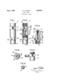
- Figure 1 is a plan elevation of the valve housing.
- Figure 2 is a plan elevation with a portion of the valve housing cutaway and shown in cross section to more fully illustrate the internal components thereof.
- Figure 3 is a cross sectional view taken along line 3-3 of Figure 2.
- Figure 4 is a cross sectional view taken along line 4-4 of Figure 2.
- FIG. 5 is a fragmentary detail illustrating the attachment of an auxiliary storage means for a reserve supply of lubricant or anti-freezing solution for the valve stem.
- Figure 6 is a plan view of the valve head of the present invention.
- 10 generally designates a valve housing which is provided with a bore 12 extending through the housing 10.
- the internal periphery of the bore 12 is threaded at each end, such as shown at 14 and 16, to receive auxiliary piping therein so that the valve may be included'in a piping system.
- the housing 10 comprises sections 18 and 20.
- Section 18 has a portion of the bore 12 formed with a reduced internal diameter at 21 and which is further provided with a bevelled edge 22 at one end thereof.
- Bevelled edge 22 constitutes a valve seat as will be hereinafter described in detail.
- Housing section 20 is provided with a central web section designated as 24 which extends diametrically across the bore 12 to divide said bore into dual passageways 12a and 12b.
- the housing section 20 has a portion of the external periphery thereof threaded complementally to a threaded portion of the internal periphery. of section 18 and said sections may be joined together in sealed relation thereby.
- Each of the sections 18 and 20 are provided with a hexagon periphery section designated as 30 and 30a respectively, to facilitate the joining together thereof.
- the diametrical portion or web 24 is provided with a projection 32 which extends longitudinally therefrom.
- the projection 32 is provided on its external periphery with threads and adapted to be disposed thereon, is a complementally threaded sleeve 34 having an aperture 36 formed in one end thereof.
- the pr0jection 32 is further provided with a bore 38 which extends through and into the Web portion 24 and communicates with a transverse bore 40.
- Transverse bore 40 further communicates with an aper ture 42 provided in one of the planes of the hexagon periphery 30a.
- a pressure type ball valve 44 may be inserted therein to facilitate the lubrication of the chamber 46 formed by the bore 38.
- a packing compound designated as 48 Disposed adjacent to the aperture 36 within the sleeve 34 is a packing compound designated as 48 which is adapted to surround valve stem 50 of the valve 52.
- the valve stem 50 is provided with a threaded end portion 53 which has a nut 54 thereon.
- a coil spring 56 is disposed to abut against a washer 58 at one end thereof and is retained in compressed relation and circumjacently disposed around the valve stem 50 by means of the nut 54. The tension of spring 56 is predetermined and sufllcient to compress the packing 48 in a sealing relationship with the valve stem 50.
- valve 52 and the valve stem 50 is sufficiently free to move longitudinally through packing 48 and the aperture 36 of the sleeve 34 as will be hereinafter described.
- the head of valve 52 When the present invention is employed in a compressed air system, the head of valve 52 is normally disposed in spaced relation from the valve seat 22 thereby permitting air to flow through the bore 12. This condition is normal and exists when a predetermined air pressure is present in the bore 12. The valve condition will not change until the pressure or flow exceeds a predetermined maximum amount. This predetermined maximum amount is determined by the tension of the spring 56. Should equipment, not shown, suddenly he removed from the air line in which the valve 10 is disposed, the increased flow of air and pressure will carry the valve 52 in the direction of flow into engagement with the valve seat 22..and effectively shut ofl-the supply of air passing through the bore 12. The head of valve 52 is provided with a small.
- the present invention is particularly adapted for utilization in pressed air systems that are exposed to freezing temperatures.
- the chamber 46 may be filled with a lubricating oil which will surround the valve stem 50 and prevent moisture from accumulating thereon. It is readily apparent that any accumulation of moisture on the valve stem would restrict the normally closing operation thereof and would render the valve useless.
- the chamber 46 may be filled with a lubricant and anti-freezing solution for reasons readily apparent.
- the embodiment shown in Figure 5 merely provides a reservoir for a reserve supply of lubrication or antifreezing solution as the case may be. Such, a reservoir would eliminate or would extend the periods during which the valve would require a manual oiling.
- This embodiment will be preferably included in-a fixed system where no flexible piping is utilized and many branches of piping are supplied by a main source. Each branch may have a valve included therein so that a rupture of any one of the pipes beyond the valve would not disturb the pressure unnecessarily throughout the entire pipe system.
- An automatic shut ofl valve comprising a housing having a through bore and including a valve seat, a valve co-operable with said valve seat and biased normally open, a valve stem supporting said valve, means integrally formed from said housing for supporting said valve stem, a chamb r disposed within said supporting means, and surrounding a substantial portion of said stem when said valve is biased open, a fluid lubricant in said chamber covering the substantial portion of the stem therein, resilient means disposed within said chamber for normally biasing said valve open, and means for sealing the fluid lubricant in said chamber.
- a member having a longitudinal bore extending therethrough, means disposed adjacent to each end of said bore for securing said member in sealed relation in a piping system, a valve seat within said member affixed to the internal periphery of said bore, a normally disposed open valve co-operating with said valve seat to effectively close said valve when actuated, resilient means normally positioning said valve in biased open elation away from the valve seat, a valve stem supporting said valve disposed within said resilient means, a lubricant surrounding said valve stem and said resilient means, and lubricant retaining means surrounding said lubricant, said lubricant retaining means comprising a chamber sealed to prevent the entry of the material flowing in said bore.
Landscapes
- Engineering & Computer Science (AREA)
- General Engineering & Computer Science (AREA)
- Mechanical Engineering (AREA)
- Lift Valve (AREA)
Description
C. C. JOHNSON SAFETY VALVE FiledA pril 19. 1955 Sept. 2-, 1958 FIG. I, F162. 12'
UZ H W HGENT Uited States Patent SAFETY VALVE (Iharles C. Johnson, Brooklyn, N. Y.
" Application April 19, 1955, Serial No. 502,395
2 Claims. (Cl. 137-517) This invention relates generally to automatic safety valves and more particularly to an automatic safety valve having a novel valve stem lubricating means.
The present invention is primarily applicable to compressed air systems but, however, may be readily utilized in any gas or liquid piping system. Many prior devices having a similar purpose to the present, i. e., to automatically shut off the flow, whether it be air or liquid should the piping beyond the valve rupture, failed to operate properly as a result of condensation forming on the valve stem and subsequently freezing into ice. The prior art devices were not reliable in low temperature areas since the freezing or immobilization of the valve stem rendered the valve useless. Such a condition is extremely dangerous and in the event of a rupturing of the pipe system utilized with the valve, said valve in its frozen condition does not shut off the supply and obviously cannot perform as a safety valve. Especially in the case of compressed air systems, a rupturing of the air hose or an accidental disconnection of the equipment being operated by the air hose causes the end of the air hose to whip uncontrollably and many serious injuries have resulted from this uncontrolled motion of the hose. With the present invention, valve stem freezing is completely eliminated and the safety shut-off fcatureof the valve prevails under all conditions and is readily dependable for the safety of the operators.
Furthermore, the present invention also provides for dependable operation of the safety factor even during extremely low temperature conditions. In this instance, an anti-freezing compound may be injected into means provided therefor which prevents condensation from accumulating and freezing into ice on the valve stem. When the present invention is utilized in a liquid piping system, the lubrication feature is unchanged and oper ates dependably without regard to the temperature of the liquid.
Therefore, one of the principal objects of the invention resides in the provision of an automatic shut-off valve having means to lubricate the valve stem to prevent freezing thereof.
Another object of the invention resides in the provision of a valve of the class described having means to store a lubricant for use in said lubricating means.
Still another object of the invention resides in the provision of a valve of the class described having means to seal the lubricant within the valve and independently of the material flowing through said valve.
Other ancillary objects will be, in part, hereinafter apparent and will be, in part, hereinafter pointed out.
In the drawings:
Figure 1 is a plan elevation of the valve housing.
Figure 2 is a plan elevation with a portion of the valve housing cutaway and shown in cross section to more fully illustrate the internal components thereof.
Figure 3 is a cross sectional view taken along line 3-3 of Figure 2.
til
Figure 4 is a cross sectional view taken along line 4-4 of Figure 2.
Figure 5 is a fragmentary detail illustrating the attachment of an auxiliary storage means for a reserve supply of lubricant or anti-freezing solution for the valve stem.
Figure 6 is a plan view of the valve head of the present invention.
Referring to the drawings in detail, 10 generally designates a valve housing which is provided with a bore 12 extending through the housing 10. The internal periphery of the bore 12 is threaded at each end, such as shown at 14 and 16, to receive auxiliary piping therein so that the valve may be included'in a piping system. The housing 10 comprises sections 18 and 20. Section 18 has a portion of the bore 12 formed with a reduced internal diameter at 21 and which is further provided with a bevelled edge 22 at one end thereof. Bevelled edge 22 constitutes a valve seat as will be hereinafter described in detail. Housing section 20 is provided with a central web section designated as 24 which extends diametrically across the bore 12 to divide said bore into dual passageways 12a and 12b. The housing section 20 has a portion of the external periphery thereof threaded complementally to a threaded portion of the internal periphery. of section 18 and said sections may be joined together in sealed relation thereby. Each of the sections 18 and 20 are provided with a hexagon periphery section designated as 30 and 30a respectively, to facilitate the joining together thereof.
As shown in Figure 3, the diametrical portion or web 24 is provided with a projection 32 which extends longitudinally therefrom. The projection 32 is provided on its external periphery with threads and adapted to be disposed thereon, is a complementally threaded sleeve 34 having an aperture 36 formed in one end thereof. The pr0jection 32 is further provided with a bore 38 which extends through and into the Web portion 24 and communicates with a transverse bore 40. Transverse bore 40 further communicates with an aper ture 42 provided in one of the planes of the hexagon periphery 30a. As shown in Figures 1, 2, 3 and 4, a pressure type ball valve 44 may be inserted therein to facilitate the lubrication of the chamber 46 formed by the bore 38. Disposed adjacent to the aperture 36 within the sleeve 34 is a packing compound designated as 48 which is adapted to surround valve stem 50 of the valve 52. As shown in Figure 3, the valve stem 50 is provided with a threaded end portion 53 which has a nut 54 thereon. A coil spring 56 is disposed to abut against a washer 58 at one end thereof and is retained in compressed relation and circumjacently disposed around the valve stem 50 by means of the nut 54. The tension of spring 56 is predetermined and sufllcient to compress the packing 48 in a sealing relationship with the valve stem 50. While this sealing relationship prevents material from entering the chamber 46 or any material in the chamber 46 from leaking into the bore 12, the valve 52 and the valve stem 50 is sufficiently free to move longitudinally through packing 48 and the aperture 36 of the sleeve 34 as will be hereinafter described.
When the present invention is employed in a compressed air system, the head of valve 52 is normally disposed in spaced relation from the valve seat 22 thereby permitting air to flow through the bore 12. This condition is normal and exists when a predetermined air pressure is present in the bore 12. The valve condition will not change until the pressure or flow exceeds a predetermined maximum amount. This predetermined maximum amount is determined by the tension of the spring 56. Should equipment, not shown, suddenly he removed from the air line in which the valve 10 is disposed, the increased flow of air and pressure will carry the valve 52 in the direction of flow into engagement with the valve seat 22..and effectively shut ofl-the supply of air passing through the bore 12. The head of valve 52 is provided with a small. through aperture 60 which permits a small amount of airto bleed through the valve when the valve is in closedrelation with the seat 22. This is provided so that a reconnection of the equipment, not shown, will permit a gradual buildup of pressure in the piping externally of the bore 12, until it is substantially equal to the pressure within the bore 12. The spring 56 overcomes the pressure and re-opens the valve 52. The equipment being operated by the air pressure may now continue inv a normal manner.
The present invention is particularly adapted for utilization in pressed air systems that are exposed to freezing temperatures. Under the average conditions for temperatur s ='.'i1l.,ii hover around the freezing mark, the chamber 46 may be filled with a lubricating oil which will surround the valve stem 50 and prevent moisture from accumulating thereon. It is readily apparent that any accumulation of moisture on the valve stem would restrict the normally closing operation thereof and would render the valve useless.
In the instances where such a system is exposed to severe freezing conditions, the chamber 46 may be filled with a lubricant and anti-freezing solution for reasons readily apparent.
The embodiment shown in Figure 5 merely provides a reservoir for a reserve supply of lubrication or antifreezing solution as the case may be. Such, a reservoir would eliminate or would extend the periods during which the valve would require a manual oiling. This embodiment will be preferably included in-a fixed system where no flexible piping is utilized and many branches of piping are supplied by a main source. Each branch may have a valve included therein so that a rupture of any one of the pipes beyond the valve would not disturb the pressure unnecessarily throughout the entire pipe system.
While there has been shown an example in which compressed air is the controlled matter, it will be understood that the present invention will operate in an identical manner with systems which include other gasses. or fluids.
Thus, it is readily evident that there has been conceived a device that is efficient and well adapted tomeet the conditions of practical use.
Whereas, it is obvious that the several objects of the invention as specifically hereinbefore set forth are achieved, it is understood. that numerous changes in construction and rearrangements of the elements may be made without departing from the spirit of the invention as defined by the following claims.
The invention claimed is:
1. An automatic shut ofl valve, comprising a housing having a through bore and including a valve seat, a valve co-operable with said valve seat and biased normally open, a valve stem supporting said valve, means integrally formed from said housing for supporting said valve stem, a chamb r disposed within said supporting means, and surrounding a substantial portion of said stem when said valve is biased open, a fluid lubricant in said chamber covering the substantial portion of the stem therein, resilient means disposed within said chamber for normally biasing said valve open, and means for sealing the fluid lubricant in said chamber.
2. In a valve of the class described, in combination, a member having a longitudinal bore extending therethrough, means disposed adjacent to each end of said bore for securing said member in sealed relation in a piping system, a valve seat within said member affixed to the internal periphery of said bore, a normally disposed open valve co-operating with said valve seat to effectively close said valve when actuated, resilient means normally positioning said valve in biased open elation away from the valve seat, a valve stem supporting said valve disposed within said resilient means, a lubricant surrounding said valve stem and said resilient means, and lubricant retaining means surrounding said lubricant, said lubricant retaining means comprising a chamber sealed to prevent the entry of the material flowing in said bore.
References Cited in the file of this patent UNITED STATES PATENTS 942,972 Palmer Dec. 14, 1909 1,446,659 Pelletier Feb. 27, 1923 1,956,010 Diescher Apr. 24, 1934 2,100,862 Lofton Nov. 30, 1937 2,354,161 Waterman July 18, 1944 2,602,631 Eickm yer July 8, 1952 FOREIGN PATENTS 127,374 Sweden 1950
Priority Applications (1)
| Application Number | Priority Date | Filing Date | Title |
|---|---|---|---|
| US502395A US2850039A (en) | 1955-04-19 | 1955-04-19 | Safety valve |
Applications Claiming Priority (1)
| Application Number | Priority Date | Filing Date | Title |
|---|---|---|---|
| US502395A US2850039A (en) | 1955-04-19 | 1955-04-19 | Safety valve |
Publications (1)
| Publication Number | Publication Date |
|---|---|
| US2850039A true US2850039A (en) | 1958-09-02 |
Family
ID=23997626
Family Applications (1)
| Application Number | Title | Priority Date | Filing Date |
|---|---|---|---|
| US502395A Expired - Lifetime US2850039A (en) | 1955-04-19 | 1955-04-19 | Safety valve |
Country Status (1)
| Country | Link |
|---|---|
| US (1) | US2850039A (en) |
Cited By (4)
| Publication number | Priority date | Publication date | Assignee | Title |
|---|---|---|---|---|
| US5901743A (en) * | 1997-01-15 | 1999-05-11 | Henke-Sass, Wolf Gmbh | Valve system, especially for use in veterinary syringes |
| US20070221272A1 (en) * | 2006-03-27 | 2007-09-27 | David Apsley | Water hose purging device |
| US8701693B2 (en) * | 2010-12-23 | 2014-04-22 | Curtiss-Wright Flow Control Corp | Nozzle check valve |
| US9383031B2 (en) | 2013-06-27 | 2016-07-05 | Curtiss-Wright Flow Control Corporation | Check valve apparatus and methods |
Citations (6)
| Publication number | Priority date | Publication date | Assignee | Title |
|---|---|---|---|---|
| US942972A (en) * | 1908-08-28 | 1909-12-14 | Stephen A Palmer | Regulating-valve. |
| US1446659A (en) * | 1921-08-13 | 1923-02-27 | Harold Depew | Air-compressor valve |
| US1956010A (en) * | 1932-03-12 | 1934-04-24 | M L R Diescher | Double acting check valve |
| US2100862A (en) * | 1933-03-02 | 1937-11-30 | Herbert M Lofton | Fire hydrant |
| US2354161A (en) * | 1943-02-08 | 1944-07-18 | Waterman William | Automatic cutoff device |
| US2602631A (en) * | 1949-11-19 | 1952-07-08 | Henry C Eickmeyer | Check valve |
-
1955
- 1955-04-19 US US502395A patent/US2850039A/en not_active Expired - Lifetime
Patent Citations (6)
| Publication number | Priority date | Publication date | Assignee | Title |
|---|---|---|---|---|
| US942972A (en) * | 1908-08-28 | 1909-12-14 | Stephen A Palmer | Regulating-valve. |
| US1446659A (en) * | 1921-08-13 | 1923-02-27 | Harold Depew | Air-compressor valve |
| US1956010A (en) * | 1932-03-12 | 1934-04-24 | M L R Diescher | Double acting check valve |
| US2100862A (en) * | 1933-03-02 | 1937-11-30 | Herbert M Lofton | Fire hydrant |
| US2354161A (en) * | 1943-02-08 | 1944-07-18 | Waterman William | Automatic cutoff device |
| US2602631A (en) * | 1949-11-19 | 1952-07-08 | Henry C Eickmeyer | Check valve |
Cited By (4)
| Publication number | Priority date | Publication date | Assignee | Title |
|---|---|---|---|---|
| US5901743A (en) * | 1997-01-15 | 1999-05-11 | Henke-Sass, Wolf Gmbh | Valve system, especially for use in veterinary syringes |
| US20070221272A1 (en) * | 2006-03-27 | 2007-09-27 | David Apsley | Water hose purging device |
| US8701693B2 (en) * | 2010-12-23 | 2014-04-22 | Curtiss-Wright Flow Control Corp | Nozzle check valve |
| US9383031B2 (en) | 2013-06-27 | 2016-07-05 | Curtiss-Wright Flow Control Corporation | Check valve apparatus and methods |
Similar Documents
| Publication | Publication Date | Title |
|---|---|---|
| US3146792A (en) | Ball valve | |
| US2245271A (en) | Safety cutoff valve | |
| US3331389A (en) | Safety cut-off valve | |
| JPS6222031B2 (en) | ||
| US2850039A (en) | Safety valve | |
| US2960996A (en) | Vacuum relief valve | |
| US2646959A (en) | Valve for controlling high pressure fluids | |
| US20170016546A1 (en) | Safety device for installation in a gas-supply system, in particular, an acetylene-supply system | |
| US2851007A (en) | Automatic poultry drinking valve | |
| CA1312802C (en) | Priority flow control valve | |
| US2968315A (en) | Predetermined pressure shut-off valve | |
| US2962038A (en) | Pressure relief assembly | |
| US2635629A (en) | Excess flow cutoff valve | |
| US2637333A (en) | Emergency valve | |
| US2841175A (en) | High pressure valve | |
| US4113284A (en) | Connection fitting | |
| US3182682A (en) | Combination telescopic valve and union | |
| US5065787A (en) | Choke valve safety device | |
| US4347867A (en) | Safety valve | |
| US3438392A (en) | Multi-purpose liquid transfer valve | |
| US2638924A (en) | Automatic tank valve | |
| US3368581A (en) | Valve for acetylene gas and the like with safety shut-off | |
| US2566774A (en) | Safety control valve | |
| US2859758A (en) | Fusible valve in liquiefied gas system | |
| US1588898A (en) | Quick opening and closing check valve for aerating systems |