US2840332A - Adjustable fittings - Google Patents
Adjustable fittings Download PDFInfo
- Publication number
- US2840332A US2840332A US381021A US38102153A US2840332A US 2840332 A US2840332 A US 2840332A US 381021 A US381021 A US 381021A US 38102153 A US38102153 A US 38102153A US 2840332 A US2840332 A US 2840332A
- Authority
- US
- United States
- Prior art keywords
- collar
- crook
- curved
- convolutions
- adjustable
- Prior art date
- Legal status (The legal status is an assumption and is not a legal conclusion. Google has not performed a legal analysis and makes no representation as to the accuracy of the status listed.)
- Expired - Lifetime
Links
Images
Classifications
-
- F—MECHANICAL ENGINEERING; LIGHTING; HEATING; WEAPONS; BLASTING
- F21—LIGHTING
- F21V—FUNCTIONAL FEATURES OR DETAILS OF LIGHTING DEVICES OR SYSTEMS THEREOF; STRUCTURAL COMBINATIONS OF LIGHTING DEVICES WITH OTHER ARTICLES, NOT OTHERWISE PROVIDED FOR
- F21V21/00—Supporting, suspending, or attaching arrangements for lighting devices; Hand grips
- F21V21/14—Adjustable mountings
- F21V21/26—Pivoted arms
-
- Y—GENERAL TAGGING OF NEW TECHNOLOGICAL DEVELOPMENTS; GENERAL TAGGING OF CROSS-SECTIONAL TECHNOLOGIES SPANNING OVER SEVERAL SECTIONS OF THE IPC; TECHNICAL SUBJECTS COVERED BY FORMER USPC CROSS-REFERENCE ART COLLECTIONS [XRACs] AND DIGESTS
- Y10—TECHNICAL SUBJECTS COVERED BY FORMER USPC
- Y10T—TECHNICAL SUBJECTS COVERED BY FORMER US CLASSIFICATION
- Y10T74/00—Machine element or mechanism
- Y10T74/20—Control lever and linkage systems
- Y10T74/20396—Hand operated
- Y10T74/20402—Flexible transmitter [e.g., Bowden cable]
- Y10T74/2045—Flexible transmitter [e.g., Bowden cable] and sheath support, connector, or anchor
Definitions
- the present invention relates to adjustable fittings and particularly, though not specifically, to adjustable fittings for electric lamps.
- An adjustable fitting comprises a curved member approximating to the arc of a circle, a ring or collar adapted to surround'said curved member and form a means whereby the fitting may be secured to a suitable support, and means on said curved member adapted to cooperate with the ring or collar so as to lock the two parts together in any one of a variety of positions, the weight of the curved member acting to retain the parts in a selected position.
- the means on the curved member may comprise a sheath fitting over said curved portion and provided with a radially-projecting helix or, alternatively, it may comprise a suitable strip or filamentary material loosely wound thereon, whereby an edge of the ring or collar may be caused to engage selectively between any two convolutions of the helix or the material.
- the lamp may be secured to one end of the curved member or an extension thereof.
- the curved member and/ or any extension of it may be hollow to receive leads from an electric lamp used on the device.
- the collar or ring may be in two parts, if desired, and is connected to a bracket whereby the device may be attached to a suitable object to serve as an adjustable lamp standard, table lamp or wall lamp, in which latter case said bracket could be aflixed to a plate for attachment to a wall.
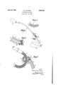
- Fig. 1 shows a perspective view of a table lamp with an adjustable fitting according to the invention.
- Fig. 2 shows a detail of the curved member in association with the ring or collar, partly in section, and
- Figs. 3 and 4 show sections through two variations of locking means and the curved member.
- a cylindrical tubular member 1 of a suitable metal such as brass
- the curved portion 2 is surrounded by helically-formed covering generally indicated at 6, a shoulder 7 being provided at one end and a stop 8 at the other to hold the covering in position.
- a cylindrical collar 9 is provided through which the curved portion is passed and has a pair of inwardly-directed flanges 10, 11, the internal diameters of which are considerably larger than the outside diameter of the spiral convolutions of the covering. For example, they may be approximately 1 /2 times that diameter.
- the collar 9 is located within the bore 12 of a bracket 13 associated with a base 14, and the difference in the i ice tion to be pushed through the collar quite easily;
- the edge of the flange 11' of the collar 9 will engage bet-ween adjacent convolutions of the covering and the weight of the device in conjunction therewith will cause the curved part 2 tobe securely gripped at the chosen position. posite portion of the curved section will rest on the op- The collar 9 maybe locked inthebore '12-by'a' screw-15.
- the helical covering member 6 may be-in'the form 0 l a sheath 16 having a radially projecting helix17 as shown in Fig. 3 or it may be in the form of a strip of filamentary material such as wire 18 loosely wound on the curved portion, as shown in Fig. 4.-
- the bracket+13 may be provided with clips 19, 20 through which the electrical leads are passed and may also be provided with a groove .21 to allow the electrical leads to lie flat;
- the collar 9 may'be provided with a piston or similar pressure device working through the wall of the bore and acting to press the curved member 2 positively against the flanges 10 and 11. 7
- the curved member 2 and the collar or ring 9 may be polygonal.
- the surface of the curved member 2 may be provided with a series of notches, grooves or corrugations for cooperation with an inner edge of thering or collar.
- An adjustable support comprising a supporting base member capable of standing freely, the upper part of said support member being shaped to form a cylinder, an annular collar located within and secured with respect to said cylinder, two inwardly-directed flanges located at the upper and lower extremities of said collar respectively, a rigid support arm one end of which is curved into a crook, and closely spaced radial projections on said crook, said crook being loosely mounted and slidable within said collar and adjustably positionable therewithin and locatable at a selected position with a part of said upper flange engaged between two adjacent ones of said projections on one side of said crook and a part of said lower flange engaged between two others of said projections diametrically opposed to said first-mentioned adjacent projections, said flanges being bevelled to form edges, said edges having substantially the same thickness as the distance between any two of said projections.
- An adjustable support comprising a supporting base member capable of standing freely, the upper part of said support member being shaped to form a cylinder, an annular collar located within and secured with respect to said cylinder in a substantially vertical position, two inwardly-directed flanges located at the upper and lower extremities of said collar respectively, a rigid support arm one end of which is curved into a crook, and a fila-' mentary helix having closely spaced convolutions mounted on said, crook, said crook being loosely mounted and slidable' within said collar and adjustably positionable therewithin and locatable at a selected position with a part of said upper flange engaged between two adjacent convolutions of said helix member on one side of said crook and a part of said lower flange engaged between two others of said convolutions diametrically opposed to said first-mentioned convolutions, said flanges being bevelled to form edges, said edges having substantially The diametrically opsatiie. thickness ,
- An adjustable support comprising a supporting base -member capable of standing-freely, the ,upper part of said support memberbeing shaped to form a cylinder, anannulancollar located within and secured with respect toisaid. cylinder-in a substantially vertical position, two
- crook being loosely mounted .and slidable within said collar and adjustably positionable therewithin and locatable at a .selectedposition with a part of saidv upper, flange engaged, :between two adjacent convolutionsofsaid helix on-one side ofsaid crook and a partofsaid lowerflange engagedbetween two others 0! said, convolutions diametrically opposed to said firsti said supportmember being'shaped to form .a cylinder,
- annular collar located within and secured with respect to said cylinder in a substantially vertical position, two inwardly-directed flanges located at the upper and lower extremities of said collar respectively, a rigid support am one end of which is curved into a crook, stop members at the two ends of said crook, and a wire coil of springy material having closely-spaced convolutions, said crook being loosely mounted and slidable within said collar and adjustably positionable therewith and locatable at a selected position with 'a part of said upper flange engaged between two adjacent convolutions on one side of said crook and a part of said lower flange engaged between two others of said convolutions diametrically opposed to said first-mentioned adjacent projections, said flanges being bevelled to form edges, said edges having substantially the same thickness as the distance between any two of said convolutions.
- An adjustable table lamp comprising a supporting base member capable of standing freely, the upper part of said supportmember being shaped to form a cylinder, an annular collar located within and secured with respect to said cylinder, two inwardly directed flanges located at the, upper and lower extremities of said collar respectively, a rigid support arm one end of which is curved into a crook, closely spaced radial projections on said crook, said crook being loosely mounted and slidable within said collar and adjustably positionable therewithin and locatable at a selected position with a part of said upper flange engaged between two adjacent ones of said projections on one side of said crook and a part of said lower flange engaged between two others of said projections diametrically opposed to said first-mentioned adjacent projections, said flanges being bevelled to form edges, said edges having substantially the same thickness as the distance between any two of said projections, and a lamp fitting at the other end of said support arm.
Description
June 24, 1958 N. J. SLUTZKY ADJUSTABLE FITTINGS Filed Sept. 18,1953
- By v l, Attorney United States Patent ADJUSTABLE FITTINGS Naum Julius Siutzky, London, England Application September 18, 1953, Serial No. 381,021 I i Claims. 01. 248-124 The present invention relates to adjustable fittings and particularly, though not specifically, to adjustable fittings for electric lamps.
An adjustable fitting according to the invention comprises a curved member approximating to the arc of a circle, a ring or collar adapted to surround'said curved member and form a means whereby the fitting may be secured to a suitable support, and means on said curved member adapted to cooperate with the ring or collar so as to lock the two parts together in any one of a variety of positions, the weight of the curved member acting to retain the parts in a selected position.
The means on the curved member may comprise a sheath fitting over said curved portion and provided with a radially-projecting helix or, alternatively, it may comprise a suitable strip or filamentary material loosely wound thereon, whereby an edge of the ring or collar may be caused to engage selectively between any two convolutions of the helix or the material.
The lamp may be secured to one end of the curved member or an extension thereof. The curved member and/ or any extension of it may be hollow to receive leads from an electric lamp used on the device.
The collar or ring may be in two parts, if desired, and is connected to a bracket whereby the device may be attached to a suitable object to serve as an adjustable lamp standard, table lamp or wall lamp, in which latter case said bracket could be aflixed to a plate for attachment to a wall.
In order that the invention may be more clearly understood, reference will now be made to the accompanying drawings which illustrate one embodiment thereof by way of example and in which:
Fig. 1 shows a perspective view of a table lamp with an adjustable fitting according to the invention.
Fig. 2 shows a detail of the curved member in association with the ring or collar, partly in section, and
Figs. 3 and 4 show sections through two variations of locking means and the curved member.
In the drawings, a cylindrical tubular member 1 of a suitable metal, such as brass, has a curved portion 2 at one end resembling the curved handle of a walking stick or umbrella and at its other end has an extension 3 carrying any desired form of electric lamp socket, lamp and shade, generally indicated at 4, the leads 5 for which are passed through the extension. The curved portion 2 is surrounded by helically-formed covering generally indicated at 6, a shoulder 7 being provided at one end and a stop 8 at the other to hold the covering in position. A cylindrical collar 9 is provided through which the curved portion is passed and has a pair of inwardly-directed flanges 10, 11, the internal diameters of which are considerably larger than the outside diameter of the spiral convolutions of the covering. For example, they may be approximately 1 /2 times that diameter.
The collar 9 is located within the bore 12 of a bracket 13 associated with a base 14, and the difference in the i ice tion to be pushed through the collar quite easily; In
posite edge of the flange 10 of the collar.
any one selected position, the edge of the flange 11' of the collar 9 will engage bet-ween adjacent convolutions of the covering and the weight of the device in conjunction therewith will cause the curved part 2 tobe securely gripped at the chosen position. posite portion of the curved section will rest on the op- The collar 9 maybe locked inthebore '12-by'a' screw-15.
The helical covering member 6 may be-in'the form 0 l a sheath 16 having a radially projecting helix17 as shown in Fig. 3 or it may be in the form of a strip of filamentary material such as wire 18 loosely wound on the curved portion, as shown in Fig. 4.- The bracket+13 may be provided with clips 19, 20 through which the electrical leads are passed and may also be provided with a groove .21 to allow the electrical leads to lie flat;
In a modification the collar 9 may'be provided with a piston or similar pressure device working through the wall of the bore and acting to press the curved member 2 positively against the flanges 10 and 11. 7
Various modifications to the specific details given could be made without departing from the scope of the invention. For example, the curved member 2 and the collar or ring 9 may be polygonal. Furthermore, the surface of the curved member 2 may be provided with a series of notches, grooves or corrugations for cooperation with an inner edge of thering or collar.
Although the invention has been specifically-described in connection with an adjustable lamp fitting it could equally well be applied to otheradjustable fittings, for example, for microphones, scientific equipment such :as retorts or test tubes and so on. a
I claim:
1. An adjustable support comprising a supporting base member capable of standing freely, the upper part of said support member being shaped to form a cylinder, an annular collar located within and secured with respect to said cylinder, two inwardly-directed flanges located at the upper and lower extremities of said collar respectively, a rigid support arm one end of which is curved into a crook, and closely spaced radial projections on said crook, said crook being loosely mounted and slidable within said collar and adjustably positionable therewithin and locatable at a selected position with a part of said upper flange engaged between two adjacent ones of said projections on one side of said crook and a part of said lower flange engaged between two others of said projections diametrically opposed to said first-mentioned adjacent projections, said flanges being bevelled to form edges, said edges having substantially the same thickness as the distance between any two of said projections.
2. An adjustable support comprising a supporting base member capable of standing freely, the upper part of said support member being shaped to form a cylinder, an annular collar located within and secured with respect to said cylinder in a substantially vertical position, two inwardly-directed flanges located at the upper and lower extremities of said collar respectively, a rigid support arm one end of which is curved into a crook, and a fila-' mentary helix having closely spaced convolutions mounted on said, crook, said crook being loosely mounted and slidable' within said collar and adjustably positionable therewithin and locatable at a selected position with a part of said upper flange engaged between two adjacent convolutions of said helix member on one side of said crook and a part of said lower flange engaged between two others of said convolutions diametrically opposed to said first-mentioned convolutions, said flanges being bevelled to form edges, said edges having substantially The diametrically opsatiie. thickness ,as the 3 distance between any two of said convolutions. V 3
p 3. An adjustable support comprising a supporting base -member capable of standing-freely, the ,upper part of said support memberbeing shaped to form a cylinder, anannulancollar located within and secured with respect toisaid. cylinder-in a substantially vertical position, two
inwardly-directed flanges located, at the upper and lower extremities of said collar respectively, a rigid support arm one end ofwhich is curved into a crook, stop members at the twoends of said crook, a, sheath member loosely mountedin said crook between;said stop members and formed with .a radially-projecting helix having closely .spaced convolutions, said. crookbeing loosely mounted .and slidable within said collar and adjustably positionable therewithin and locatable at a .selectedposition with a part of saidv upper, flange engaged, :between two adjacent convolutionsofsaid helix on-one side ofsaid crook and a partofsaid lowerflange engagedbetween two others 0! said, convolutions diametrically opposed to said firsti said supportmember being'shaped to form .a cylinder,
an annular collar located within and secured with respect to said cylinder in a substantially vertical position, two inwardly-directed flanges located at the upper and lower extremities of said collar respectively, a rigid support am one end of which is curved into a crook, stop members at the two ends of said crook, and a wire coil of springy material having closely-spaced convolutions, said crook being loosely mounted and slidable within said collar and adjustably positionable therewith and locatable at a selected position with 'a part of said upper flange engaged between two adjacent convolutions on one side of said crook and a part of said lower flange engaged between two others of said convolutions diametrically opposed to said first-mentioned adjacent projections, said flanges being bevelled to form edges, said edges having substantially the same thickness as the distance between any two of said convolutions.
5. An adjustable table lamp comprising a supporting base member capable of standing freely, the upper part of said supportmember being shaped to form a cylinder, an annular collar located within and secured with respect to said cylinder, two inwardly directed flanges located at the, upper and lower extremities of said collar respectively, a rigid support arm one end of which is curved into a crook, closely spaced radial projections on said crook, said crook being loosely mounted and slidable within said collar and adjustably positionable therewithin and locatable at a selected position with a part of said upper flange engaged between two adjacent ones of said projections on one side of said crook and a part of said lower flange engaged between two others of said projections diametrically opposed to said first-mentioned adjacent projections, said flanges being bevelled to form edges, said edges having substantially the same thickness as the distance between any two of said projections, and a lamp fitting at the other end of said support arm.
References Cited in the file of this patent UNITED STATES PATENTS 426,163 Bergmann Apr. 22, 1890 1,054,892 Anklam Mar. 4, 1913 7 1,356,745 Schwartz et al. Oct. 26,1920 1,360,559 Monahan Nov. 30, 1920 2,133,020 Fehrenbach Oct. 11, 1938 2,335,296 Miller Nov. 30, 1943 2,456,792 Ohm Dec. 21, 1948 2,721,719 Giese et al. Oct. 25, 1955
Priority Applications (1)
| Application Number | Priority Date | Filing Date | Title |
|---|---|---|---|
| US381021A US2840332A (en) | 1952-08-06 | 1953-09-18 | Adjustable fittings |
Applications Claiming Priority (2)
| Application Number | Priority Date | Filing Date | Title |
|---|---|---|---|
| GB19804/52A GB732984A (en) | 1952-08-06 | 1952-08-06 | An adjustable bracket arm or like support for lamps or other articles |
| US381021A US2840332A (en) | 1952-08-06 | 1953-09-18 | Adjustable fittings |
Publications (1)
| Publication Number | Publication Date |
|---|---|
| US2840332A true US2840332A (en) | 1958-06-24 |
Family
ID=10135503
Family Applications (1)
| Application Number | Title | Priority Date | Filing Date |
|---|---|---|---|
| US381021A Expired - Lifetime US2840332A (en) | 1952-08-06 | 1953-09-18 | Adjustable fittings |
Country Status (6)
| Country | Link |
|---|---|
| US (1) | US2840332A (en) |
| CH (1) | CH315455A (en) |
| DE (1) | DE1002080B (en) |
| FR (1) | FR1083976A (en) |
| GB (1) | GB732984A (en) |
| NL (1) | NL81312C (en) |
Cited By (5)
| Publication number | Priority date | Publication date | Assignee | Title |
|---|---|---|---|---|
| US3430640A (en) * | 1964-02-17 | 1969-03-04 | Gen Electric | Supersonic inlet |
| US6789775B2 (en) * | 2002-08-28 | 2004-09-14 | News America, Inc. | Flexible connection system for a mounting device |
| US20080197247A1 (en) * | 2007-02-15 | 2008-08-21 | Lovro Gotovac | Stand apparatus |
| US20160241939A1 (en) * | 2015-02-13 | 2016-08-18 | Bogen Communications, Inc. | Speaker mounting assembly |
| US11051500B2 (en) * | 2019-05-03 | 2021-07-06 | Winthrop Tackle | Adjustable butt and reel seat for a fishing rod |
Families Citing this family (2)
| Publication number | Priority date | Publication date | Assignee | Title |
|---|---|---|---|---|
| DE3264263D1 (en) * | 1981-07-17 | 1985-07-25 | Siemens Ag | Supporting arm adjustable in height, involving a parallelogram coupling |
| DE29705519U1 (en) * | 1997-03-27 | 1997-05-28 | Vettermann Roland | Swiveling holder for a lamp |
Citations (8)
| Publication number | Priority date | Publication date | Assignee | Title |
|---|---|---|---|---|
| US426163A (en) * | 1890-04-22 | Sigmund bergmann | ||
| US1054892A (en) * | 1912-03-29 | 1913-03-04 | Hall C M Lamp Co | Lamp-bracket. |
| US1356745A (en) * | 1918-02-15 | 1920-10-26 | Alfred Gauthier J | Coupling for electric-light fixtures |
| US1360559A (en) * | 1919-10-16 | 1920-11-30 | Ber J Daly | Air-hose stand |
| US2133020A (en) * | 1936-07-15 | 1938-10-11 | Fehrenbach Anton | Slip-on shower spray holder |
| US2335296A (en) * | 1941-10-17 | 1943-11-30 | Samuel C Miller | Adjustable insulating elevation post |
| US2456792A (en) * | 1946-12-12 | 1948-12-21 | Markel Electric Products Inc | Wall bracket electric light fixture |
| US2721719A (en) * | 1951-09-15 | 1955-10-25 | Mcgraw Electric Co | Adjustable bracket |
Family Cites Families (1)
| Publication number | Priority date | Publication date | Assignee | Title |
|---|---|---|---|---|
| AT121684B (en) * | 1930-02-14 | 1931-03-10 | Ditmar Geb Bruenner Ag | Swivel device for lamps. |
-
1952
- 1952-08-06 GB GB19804/52A patent/GB732984A/en not_active Expired
-
1953
- 1953-09-18 US US381021A patent/US2840332A/en not_active Expired - Lifetime
- 1953-09-24 FR FR1083976D patent/FR1083976A/en not_active Expired
- 1953-09-24 CH CH315455D patent/CH315455A/en unknown
- 1953-11-24 NL NL183088A patent/NL81312C/xx active
- 1953-11-25 DE DES36488A patent/DE1002080B/en active Pending
Patent Citations (8)
| Publication number | Priority date | Publication date | Assignee | Title |
|---|---|---|---|---|
| US426163A (en) * | 1890-04-22 | Sigmund bergmann | ||
| US1054892A (en) * | 1912-03-29 | 1913-03-04 | Hall C M Lamp Co | Lamp-bracket. |
| US1356745A (en) * | 1918-02-15 | 1920-10-26 | Alfred Gauthier J | Coupling for electric-light fixtures |
| US1360559A (en) * | 1919-10-16 | 1920-11-30 | Ber J Daly | Air-hose stand |
| US2133020A (en) * | 1936-07-15 | 1938-10-11 | Fehrenbach Anton | Slip-on shower spray holder |
| US2335296A (en) * | 1941-10-17 | 1943-11-30 | Samuel C Miller | Adjustable insulating elevation post |
| US2456792A (en) * | 1946-12-12 | 1948-12-21 | Markel Electric Products Inc | Wall bracket electric light fixture |
| US2721719A (en) * | 1951-09-15 | 1955-10-25 | Mcgraw Electric Co | Adjustable bracket |
Cited By (9)
| Publication number | Priority date | Publication date | Assignee | Title |
|---|---|---|---|---|
| US3430640A (en) * | 1964-02-17 | 1969-03-04 | Gen Electric | Supersonic inlet |
| US6789775B2 (en) * | 2002-08-28 | 2004-09-14 | News America, Inc. | Flexible connection system for a mounting device |
| US20050023430A1 (en) * | 2002-08-28 | 2005-02-03 | George Kringel | Flexible connection system for a mounting device |
| US20080197247A1 (en) * | 2007-02-15 | 2008-08-21 | Lovro Gotovac | Stand apparatus |
| US20110290950A1 (en) * | 2007-02-15 | 2011-12-01 | Lovro Gotovac | Stand apparatus |
| US8087629B2 (en) * | 2007-02-15 | 2012-01-03 | Lovro Gotovac | Stand apparatus |
| US20160241939A1 (en) * | 2015-02-13 | 2016-08-18 | Bogen Communications, Inc. | Speaker mounting assembly |
| US9602902B2 (en) * | 2015-02-13 | 2017-03-21 | Bogen Communications, Inc. | Speaker mounting assembly |
| US11051500B2 (en) * | 2019-05-03 | 2021-07-06 | Winthrop Tackle | Adjustable butt and reel seat for a fishing rod |
Also Published As
| Publication number | Publication date |
|---|---|
| FR1083976A (en) | 1955-01-14 |
| NL81312C (en) | 1956-04-16 |
| DE1002080B (en) | 1957-02-07 |
| GB732984A (en) | 1955-07-06 |
| CH315455A (en) | 1956-08-15 |
Similar Documents
| Publication | Publication Date | Title |
|---|---|---|
| US2902592A (en) | Portable lamp | |
| US2642246A (en) | Adjustable support stand | |
| US2673966A (en) | Device consisting of rotatable and extensible means for conducting electrical current | |
| US2840332A (en) | Adjustable fittings | |
| US1640434A (en) | Socket adapter | |
| US2278852A (en) | Electrical insulator attachment device | |
| US1640189A (en) | Lamp socket | |
| US2677756A (en) | Lamp shade and supporting spider | |
| US2424804A (en) | Pass-through insulator | |
| US1865179A (en) | Lamp stand | |
| US1575245A (en) | Lamp-bulb support | |
| US3069582A (en) | Lamp filament connection | |
| US2302031A (en) | Photographic apparatus | |
| US2673927A (en) | Lampshade adapter | |
| US1423646A (en) | Electric fixture | |
| US2596006A (en) | Means for attaching electric lamp sockets to tubular lamp bases | |
| US1114299A (en) | Electric-light fixture. | |
| US1917675A (en) | Adjustable resistance device | |
| US1117131A (en) | Lamp-shade. | |
| US2444278A (en) | Adapter for electric lamps | |
| US2703000A (en) | Means for mounting inverted incandescent mantles | |
| US2049562A (en) | Electrical thermostat | |
| US1491094A (en) | Focusing device | |
| US2058847A (en) | Holding device for lamp shade frames | |
| US2061757A (en) | Lamp shade support |