US2828126A - Sheet feeding apparatus and method - Google Patents
Sheet feeding apparatus and method Download PDFInfo
- Publication number
- US2828126A US2828126A US475804A US47580454A US2828126A US 2828126 A US2828126 A US 2828126A US 475804 A US475804 A US 475804A US 47580454 A US47580454 A US 47580454A US 2828126 A US2828126 A US 2828126A
- Authority
- US
- United States
- Prior art keywords
- sheet
- suction
- blank
- friction
- plane
- Prior art date
- Legal status (The legal status is an assumption and is not a legal conclusion. Google has not performed a legal analysis and makes no representation as to the accuracy of the status listed.)
- Expired - Lifetime
Links
Images


Classifications
-
- B—PERFORMING OPERATIONS; TRANSPORTING
- B31—MAKING ARTICLES OF PAPER, CARDBOARD OR MATERIAL WORKED IN A MANNER ANALOGOUS TO PAPER; WORKING PAPER, CARDBOARD OR MATERIAL WORKED IN A MANNER ANALOGOUS TO PAPER
- B31B—MAKING CONTAINERS OF PAPER, CARDBOARD OR MATERIAL WORKED IN A MANNER ANALOGOUS TO PAPER
- B31B50/00—Making rigid or semi-rigid containers, e.g. boxes or cartons
- B31B50/02—Feeding or positioning sheets, blanks or webs
- B31B50/04—Feeding sheets or blanks
- B31B50/06—Feeding sheets or blanks from stacks
- B31B50/062—Feeding sheets or blanks from stacks from the underside of a magazine
- B31B50/064—Feeding sheets or blanks from stacks from the underside of a magazine by being moved in the plane they are lying in
Definitions
- the principal object of this invention is'to provide .a
- FIG. '2 is a side elevation of the device in section on line 2-2 of Fig. 1 showing the parts in their respective positions with the flat friction face of the suction cups lifted verticallyand adhering to the exposed face of an end blank. 7
- Fig. 3 is a view similar to Fig. 2 showing the suction cupsadvanced rectilinearly in the plane of the end blank, the end blank having passed through the magazine gateway and 'been'gripped by the blank gripping and advancing-mechanism.
- Fig. 4 is a view similar to Fig. 2 showing the flat friction face of the suction cups released from adherence to the blank and drawn vertically downwardly outof the plane oftheend blank;
- Fig. 5 is a view similar to Fig. 2 showing the. suction cups retracted rectilinearly in a plane parallel to the, plane of an and blank but spaced therebelow and ready to be lifted; vertically. to engage the next succeeding blank.
- .1 .7 .l a r I Fig. ,6 is an end-view ofthe device shown in Fig. 1.
- Fig. 8 is aside view of ,the device'shown in Fig. 7,
- FIG. 9 is a view-similar to Fig. 8 showing the friction face retra'ctedslightl-y below the plane o'f the paper linetomary to move an adhered cup perpendicularly away from r the stack or in a curved line having a perpendicular component since it has been the teaching that an adhered friction surfaces tangentially to a sheet for feeding rather than perpendicularly.
- a further object of the invention istoprovide'a novel support and actuating mechanism for such friction faced suction cups which maintains the friction face of the cups in the plane of the end sheet while moving the cups for a considerable distance in a plane parallel to the plane of the'sheet and then returns the cups to their original position.
- Still another object of the invention is to provide friction and suction sheet segregating mechanism on a bottom feed magazine with the magazine having a fixed, antifriction platform extending across the entire bottom of the magazine for supporting the sheets thus assisting in "the slideable segregation of the successive end sheets.
- a still further object of the invention is to provide a novelniethod of applying a friction faced. suction cup to a stack for segregating the end sheets thereof, the method including moving the same through aclosed substantially angular'path which path is preferably rectangular.
- Another object of the invention is to provide a sheet feeding element moveable in a straight line for a short distance relative to the size of a sheet to advance asheet into a gateway together with means; for temporarily opening'the gateway to accommodate a second sheet until the first sheet has entirely passed therethroughj
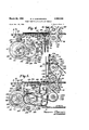
- f Fig. 1 is a plan view of the invention meunted at the feed end of'a paper box foldingmachine.
- Fig. 1A is an enlarged, fragmentary, side view of a V frictiOn rimmed suction cup of the inventioni and endmostisheet tolbow the sheet and I Fig. 10 is a view similar to Fig; 8 showing the friction face being returnedgto the plane of the paper line after the end sheet has been advanced toward the/separator. means, v v
- the magazine mechanism is designated A
- the sheet gripping and advancing means is. designated B
- the paper boxfolding machine on' which the invention is illustrated may be of anywell known,
- the machine includes a frame 20 having the usual side frame pieces 21 and 22.
- the structure of the, frame includes a plurality of laterally extending rods such as at 23 which constitute frame pieces but upon which the'parts of the machine may beslideably mountedto accommodate blanks of various dimensions.
- the sheet, or blank, 24 may be of any well known type, depending on the purpose of the machine, and is the endor bottom sheet of a stack 25 of flat blanks all identical to the blank 24. The next succeeding end blankinthe stack is designated 26. 7 V V Magazine mechanism.
- Front guide is in" the form of a vertically slideable and adjustable gate which may be fixed in position at a spaced distance from another separator member to form a gateway 31 opposite the leading edge32 of the end sheet 24.
- Gateway 31 is normally of a height equal to the thickness of a single sheet or blank in themagazine, thereby permitting the passage of only one sheetat a time.
- a stationary platform, or shelf 34', constituting the other separator member forms th'e lower edge of gateway 31 and supports the undersurfaceof the leading edge portions of the sheets in stack 25.
- Stationary platform 34 3 platform 37 is provided for sheets in stack 25.
- a plurality of brackets such as 38 are fixed on cross rod 23for lateral positioning by means of set screws 39;
- Each bracket 38 supports a longitudinally extending bar 40 which bar in turn carries a row of freely revolvable rollers such as 41. .
- the laterally spaced apart rows of rollers 41 extendin the direction of advance of a blank toward gateway 31 and are freely revolvable on axes of rotationsuch as at 45 which are parallel to, but below the plane of'the gateway 31.
- Each bracket 38 includesa vertical rod 46 fixed to a bar 40 at 47 and verticallypositioned at various heights in a suitable bracket slot by means of set screw '48.
- the forward ends such as 42 of each rod 40 are supported on a transversely extending leg support such as-44. (See Fig.2.)
- the sheet gripping and advancing mechanism B of the invention is positioned outside the gateway 31 and includes a pair of rotating members 50 and 51 having a nip 52 in the path of a sheet or blank emerging from the gateway 31'.
- -Member 51 is preferably a roll having a smooth circumferential surface .53 and revolved in synchronization with the remaining parts of the folding machine by-a power shaft 54 in a .well known manner.
- Member 50 may also be a roll oppositely disposed to roll supporting the weight of the longitudinally extending tracks 79 and 80. Plates 75 and 76 are joined by a laterally extending shaft 81, upon which collars such as 82 are slidable and adjustable in various lateral positions by set screws such as 84.
- Each suction cup such as 65 is carried at the forward ends of a bar 85, each bar being longitudinally slidable and adjustable in a collar 82 by set screws such as 87.
- each suction cup such as 65 each supported by one of a pair of vertically extending rods 89 and 90, the rods 89 and 90 being slidably guided insuitable brackets such as 91 and 92 having lugs such as at 88 for attachment to 'a frame side piece 21 or 22.
- the tracks 79. and 80 guide the carriage 74 in a straight line advancing and retracting path, the rods 51 and having a friction insert of any well known type..
- Member 50 is' carried by a power shaft 55, similar to shaft 54, and preferably, however, includes a smooth surface 56 and a toothed or corrugated surface 57.
- the surface 57 leads surface 56 as member 50 rotates in the direction of the arrows and-is formed of a narrow strip of laterally extending sharp teeth, such as 58, which project radially beyond surface 56.
- Teeth 58 thus make a tight nip at 52 and in cooperation with member 51, grip and positively advance a sheet or blank received therebetween into the conveyor chains or belts 60 and 61.
- a cut away portion 62 in the circumference of roll 50 permits the leading edge portion of a sheet to be advanced into the nip of the rolls and 51 before the sheet is engaged and advanced by. the teeth 58.
- the sheet segregating mechanism C of the invention in cludes a flat friction surfaceiof considerable area formed by suction cups such. as 65, each preferably of resilient material such as rubberfand each connected by a flexible tube such as 67 to suction means 69.
- Suction means 69 includesan air suction pipe 70,v extending laterally across the machine, and rearwardlyto arotary valve 68 of a type well known in the art and not illustrated in detail.
- the valve 68 of the suction means' is synchronized with the mechanical means of the segregating mechanism to cause air to be exhausted from the cups such as 65 dura Mechanical means 94 is provided for successively ac-.
- a pair of means 94 includes yoke. type cam followers 95 and 96 each encircling one of a pairv of eccentric cams 97 and 98 at one end and having its other end connected to a plate 75 or 76 of carriage 74 as by a link 99 or 100.
- the eccentric cams 97 and 98 are carried at opposite ends of a drive shaft 104 whereby with each rotation of shaft 104 carriage 74 is advanced and retracted in tracks 79 and 80.
- Means 94 also includes a rocker arm 106 pivotally mounted at 107 to a lateral shaft 108 and having their advancing motion and to be admitted to the cups during their return motionwThis is accomplished by mounting the valve 68 on the same shaft 104 that operates the cams of mechanical means 94 to be described hereinafter.
- Valve 68 is fed by a pipe 66 leading to a suitable pump and tank of any well known type and therefore not shown. It should be noted that the plane of the fiat friction face 71 an d the coplanar suction opening 72 of each cup such as is parallelto the fiat plane of the bottom blank 24 in stack 25.
- Mechanism .C includessuction cupsupport means 73 for supporting and guiding :thefriction faced suction cups ing one terminal end1109 pivotally connected to a rod 89, as by a link '110.”
- Arm 106 carries a cam follower 111 at its opposite terminal end 105, follower 111 riding in cam track 112 of a-rotating cam 113 mounted on drive shaft 104.
- a rocker arm 5102 similar to arm 106, is fixed to the opposite end of shaft 108 and connected to rod 90 by a link 103 thereby causing both plates and 76 of carriage 74 to rise and fall in unison.
- mechanical means 94 causes the carriage 74 to advance towardgateway 31 in a straight line in tracks 79 and 80, then causes the tracks 79 and with carriage 74 tovbe lowered away from the stack 25, then retracts the carriage 74 in the 7 tracks 79 and 8t ⁇ and then raises the tracks with the car- .65 in a closed substantially angular path while retaining 5 l riage 74-back to their original position, thus completing acycle.
- the mechanical means 94 causes support means 73 to move the friction face 71 of a suction cup 65 substantially perpendicularly up to the undersurface of the bottomor end sheet 24 of a stack, at which time the suction means 69 exhausts air from the cup and frictionface 7 1 enabling the cup to-adhere to the sheet.
- the suction means 69 causes support means 73 to movethe cup' horizontally in a straight line to ward gateway31- sliding the leading edge of bottom blank 24 through the gateway and intoithe nip of the rotating members 50 and 51;. ;Suction means 69 then-admits air to cup 65, thereby enabling the cup to. release sheet 24 from its friction -face, 71; ;while' means 94draws the cup 65, carriage 74 and -tracks79 and 80 in'astraight line downwardly and perpendicularly away from the stack 25.
- Means 94 then retracts; the carriage74 in tracks 79- and nannies.
- the tracks 79 and 80 move only in a straight line. up and down and the carriage 74 moves only in a straight line hori'zontallyrelative to the tracks, it will be apparent. that. the return portion of the closed path of the cups 65, while substantially angular, may include arcuate portions due. to the composite paths.
- each suction cup 65 is. preferably of considerable area and preferably a comparatively large number of such cups such-as five, 01 more are provided in order to. increase the frictional engagement with each endmost sheet and thereby avoid slippage.
- the suction openings 72 of the cups 65 not. only tend to adhere to the end sheet but draw the sheet toward the friction surfaces 71 thereby increasingthe. strength of the grip attained thereby.
- the surfaces. 71. are not only of a friction material such as rubber, but are preferably roughened to increase such friction.
- Separator .30 includes a tapered lower portion 120 for fanning out the sheets in stack 25 as they approach gateway 31 and is pivotally mounted at 121 and 122 to links such as 123 and 124. Links 123 and 124 are pivoted at 125 and 126' to. a bracket 127 depending from cross frame rod 128'. V A pair of shorter pivoted links such as 138 are provided to limit and guide the movement of the lower end of separator 30.
- Separator 30 may thus be lifted on its pivot mounting to enlarge gateway 31 but separator 30 falls by gravity back to its initial position established by stop arm 130 and stop pin 131 after such lifting.
- a shaft 132 extends laterally of frame 20 and is journalled at 133' in bracket 127, shaft 132 carrying a pair of cams such as 134 and 135 arranged to engage a pair of cam followers such as 136 and 137 on links 123 and124..
- Stop pin 131 is threadedly mounted in arm 130 for adjustment to permit passage of single blanks of various thicknesses and a knob and thrust screw 129 is provided for adjusting separator 30 to permit passage of double blanks whenfollowers 136, 137 are at the high point of the cams.
- the friction face or surface, formed by the suction cups 65 or otherwise by reason of the. mechanism for angularmovement, approaches each endmost sheet substantially perpendicularly while in a flat plane parallel to the flat plane of the sheet and there fore adheres by friction, or friction and suction, simul-. taneously over a large area of the sheet.
- friction, or friction and suction, simul-. taneously over a large area of the sheet There is no component of advancing force inthe direction of feed at, this time and such component occurs only after at 1.11 and cpmpletev adhesion has been secured to prevent any slippage.
- Thesheet is thus positively registered for passage through the machine and no further registration is. necessary.
- the suction cup support means C is unchanged but in;
- a gear 149 on shaft 148 is meshed with a gear 150 on shaft 104 for rotating shaft 104.
- another gear 151 is carried by shaft 148 and another gear 152 is carried by shaft 104 whereby two speeds may be secured for the mechanical means 94 and valve 68 of suction means 69 with relation to the speed of rotation of the rolls 50 and 51.
- the circumference of the pinch roll 50 is about twelve and one half inches
- the forward travel of the cups is about two and one half inches
- the distance from the gateway 31 to the nip 52 of rolls 50 and 51 is about two and one quarter inches.
- the suction cup 165 is carried at the terminal end ofv housing 186 and includes a suction opening 190 anda friction face 191. formedby the rim.
- a collapsible bellows 192 connects suction cup 165 to the suction tube 193 the tube 193 being in turn connected to the flexible air suction, or air exhaust pipe 70.
- the outwardly projecting lug 199 on housing186 travels along an upwardly'inclined, fixed track. 200 to forcibly lift the suction cup 165 and housing 186 back to its initial level with the faces 191 again 'coplanar'with the planeof the Yendblank 'and the paper li'nef'As shown, the track 200 may conveniently be formed in one. of .the longitudinally extending support bars 201 corresponding to bars40, of the magazine.
- the above described device is especially useful with heavy paper stock havingdeeply defined creases to the extent that the bottom ofrthelcrease in .one blank nests in the recess, of the crease of thenext lower blank and prevents sliding movement of the latter.”
- Apparatus for automatically and successively sliding and separating each individual fiat paperbox blank from-the bottom of. a stack of flat blanks saidapparatus including magazine mechanism for supporting said stack and having a gateway opposite the leading edge of the bottom blank for passing'one blank at a time; sheet gripping and advancing mechanism mounted outside the gateway of said magazine and having.
- suction sheet segregating mechanism operable upon the exposed face of each bottom blank of the stack, said mechanism including a suction cup having a flat friction face therearound of substantial area extending in a plane parallel to the plane of said bottom blank, suction means for intermittently exhausting air from said cup; suction cup support means for supporting and guiding said friction faced suction cup in a closed substantially angular unidirectional path, while retaining the friction face thereof in said plane, said path having, an elongated rectilinear component coinciding with the flat plane of said bottom blank and leading to said gateway and having its remaining components below and spaced from the flat plane of said bottom blank, and mechanical means, synchronized with said suction means, for actuating said suction cup support means to move said friction faced suction cup along said closed angular path.
- said magazine mechanism includes a roller platform formed by at least two spaced apart parallel rows of rollers, each row extending entirely across the bottom of the magazine in the direction of advance of a blank and each roller being freely revolvable on an axis of rotation parallel to, but
- said magazine mechanism includes a stationary'shelf under the leading edge portion of the bottom'blank of the stack and a roller platform extending rearwardly therefrom entirely under the middle and trailing portion of said blank, said shelf and'platform being in a common fiat mechanical means for actuating the suction cup support means includes'yoke follower arm'and cam means for same in its vertical components, said cams being gases moving'the same in itshorizontal components andv roller follower rocker, armfand cam, means, forfmoving the rotatable with a common'shaft.
- Apparatus as specified gripping and advancing mechanism is'synchronized with said suction sheet segregating mechanism. and one of the rotatable members. of said sheet gripping and advancing t mechanismis provided 'witha circumferential face having aneIong'ated'raised toothed, arcuate section and an elongated depressed, smooth, arcuate section, said raised toothed arcuate section beingadapted to grip ablank, and saidismooth depressedjarcuate section being adapted to pass a blank in cooperationwith the circumferential face of the other rotating member ,of the pair.
- Apparatus for, automatically and. successively slidably segregating each individual flat sheet from the end of a stack of such sheets said apparatus comprising a suctioncup having a fiat friction face of substantial area therearound in a plane parallel to the plane of said end sheet; suction means for intermittently exhausting air from saidfriction faced cup; suction cup support means for supporting and guiding said suction cup in a closed substantially angular uni-directional path while retaining the friction face thereof ina plane substantially parallel to the plane of the end sheet, said path having an elongated component substantially parallel to the plane of the end sheet and having its-remaining components all in a plane perpendicular to the plane of said end sheet and mechanical means, synchronized with said friction faced suction means, for successively actuating said suction cup support means to move said suction cup along said closed angular path.
- a suction cup having a fiat friction face therearound adapted to frictionally'eng'age a substantial area of the exposed face of a blank; a carriage supporting said suction cup with the flat friction face thereof always parallel to the plane of the end sheet in said stack; a pair of laterally spaced straight tracks slideably supporting said carriage and each extending in a plane parallel to the fiat plane of said end sheet; a pair of straight rods each slideably mounted on said machine, each rod supporting one of said tracks and extending in a plane perpendicular to the plane of said end sheet; a pair of connecting arms on said machine each having one terminal end pivotally connected to said carriage andhaving a yoke cam follower at its other terminal end; a pair ofeccentric cams on a cam shaft each foractuating one of said yoke cam followers; 2.
- Blank feeding mechanism for use in slideably advancing flat blanks from the end of a stack in a paper box folding machine, said mechanism comprising a magazine for holding a stack of flat blanks; a flat friction face of substantial area formed by spaced apart, flat, rims of a plurality of suction cups, for successively adhering to the exposed face of each successive end blank in said magazine; a carriage for supporting said suction cups; a pair of tracks each mounted on an opposite side of said machine below said magazine and extending rectilinearly parallel to the direction of slideable advance of a blank for slideably supporting and guiding each opposite end of said carriage; a pair of rods, each mounted on an opposite side of said machine below a track and extending rectilinearly perpendicular to said direction of advance of a blank for slideably supporting and guiding one of said tracks; means for continuously raising said tracks perpendicularly toward the exposed face of an end blank, then advancing said carriage in said tracks, parallel to the fiat plane of an end blank then lowering said tracks per
- the method of individually and successively feeding the endmost sheet from a stack of flat sheets which comprises moving a fiat friction face, of substantial sheet engaging area, perpendicularly up to a position fiatwise against the exposed face of an endmost sheet with no component tending to slideably advance the sheet off the stack, then drawing said sheet face by suction into firm adherence with said friction face, then advancing said friction face in the direction of feeding, while adhered to said endmost sheet a predetermined distance and completely halting said friction face and then releasing said suction adherence and returning said friction face to its initial position by a path removed from said endrnost sheet and stack, all while said friction face is parallel to the plane of said endmost sheet.
Description
March 25, 1958 v R. A. LABOMBARDE 2 SHEET FEEDING APPARATUS AND METHOD Filed Dec. 16, 1954 5 Sheets-Sheet 1 6 'Figl.
. mmvrox. 1 am A. LABOMBARDE BY ATTORNEYS March 1953 y R. A. LABOMBARDE 2,828,126
SHEET FEEDING APPARATUS AND METHOD Filed Dec. 16, 1954 5 sheets -sheet 2 o o 4 47 55 a4 3 V F1! L l// r"-' *1? 25 Q39 6 1 53 I 70 69 "35. INVENTOR. G MONDALABQBEARDE Fig. 3. T ATI bRNEYS March 25, 1958 A R. A. LA BYOIVYIBARDE 2, ,1
SHEET FEEDING APPARATUS AND METHOD Filed Dec. 16, 1954 Sheets-Sheet :5
" o 06-eoo- ,o '47 23 "38 77274 iv A e v1.14 INVENTOR- m I r A y? 55 RAYggONDA. I E
R. A. LABOMBARDEI 2,828,126
SHEET FEEDING APPARATUS AND METHOD March 25, 1958 5 Sheets-Sheet 4 Filed Dec. 16, 1954 INVENTOR., x mm 41430111341201? ATTORNEYS March 25, v1958 R. A. LABOMBARDE 2,828,126
SHEET FEEDING APPARATUS AND METHOD 5 sheets sneet 5 Filed Dec. 16, 1954 @J AW INVENTOR. RAKMOND A. LABOMBARDE BY PM '"PM ATTORNEYS v 7 2 ,828,126 SHEET FEEDING APPARATUS AND METHOD Raymond ,A.'Labon1harde, Nashua, N. H. Application-December :16, 1954', Serial No.47 5,804
12 Claims. c1. m -s2 "This invention relates to sheet feeding devices for use in paper box folding machines. It especially relates to an improved machine and methodfor segregating the end blank from a stack of box blanks by the use of an angularly movable friction surface including suction cups..
The principal object of this invention is'to provide .a
movea'ble friction. surface formed by flat, enlarged. rims 2,828,126 Patented Mar. 25, 1958 Fig. '2 is a side elevation of the device in section on line 2-2 of Fig. 1 showing the parts in their respective positions with the flat friction face of the suction cups lifted verticallyand adhering to the exposed face of an end blank. 7
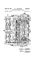
Fig. 3 is a view similar to Fig. 2 showing the suction cupsadvanced rectilinearly in the plane of the end blank, the end blank having passed through the magazine gateway and 'been'gripped by the blank gripping and advancing-mechanism. v
Fig. 4 is a view similar to Fig. 2 showing the flat friction face of the suction cups released from adherence to the blank and drawn vertically downwardly outof the plane oftheend blank;
Fig. 5 is a view similar to Fig. 2 showing the. suction cups retracted rectilinearly in a plane parallel to the, plane of an and blank but spaced therebelow and ready to be lifted; vertically. to engage the next succeeding blank. .1 .7 .l a r I Fig. ,6 is an end-view ofthe device shown in Fig. 1. a FigITis'Qa planview of atpreferred form of suction cup and cup support means.
, Fig. 8 is aside view of ,the device'shown in Fig. 7,
with the friction faceithereof coplanar with the paper line and some of the parts sectionalized.
-Fig."9 is a view-similar to Fig. 8 showing the friction face retra'ctedslightl-y below the plane o'f the paper linetomary to move an adhered cup perpendicularly away from r the stack or in a curved line having a perpendicular component since it has been the teaching that an adhered friction surfaces tangentially to a sheet for feeding rather than perpendicularly.
A further object of the invention istoprovide'a novel support and actuating mechanism for such friction faced suction cups which maintains the friction face of the cups in the plane of the end sheet while moving the cups for a considerable distance in a plane parallel to the plane of the'sheet and then returns the cups to their original position.
Still another object of the invention is to provide friction and suction sheet segregating mechanism on a bottom feed magazine with the magazine having a fixed, antifriction platform extending across the entire bottom of the magazine for supporting the sheets thus assisting in "the slideable segregation of the successive end sheets.
A still further object of the invention is to providea novelniethod of applying a friction faced. suction cup to a stack for segregating the end sheets thereof, the method including moving the same through aclosed substantially angular'path which path is preferably rectangular. I
Another object of the invention is to provide a sheet feeding element moveable in a straight line for a short distance relative to the size of a sheet to advance asheet into a gateway together with means; for temporarily opening'the gateway to accommodate a second sheet until the first sheet has entirely passed therethroughj Other objects and advantages of the invention will appear in the following description of a specific-embodiment of the same, together with th'e drawings andclainis. In the drawings, f Fig. 1 is a plan view of the invention meunted at the feed end of'a paper box foldingmachine. t
Fig. 1A is an enlarged, fragmentary, side view of a V frictiOn rimmed suction cup of the inventioni and endmostisheet tolbow the sheet and I Fig. 10 is a view similar to Fig; 8 showing the friction face being returnedgto the plane of the paper line after the end sheet has been advanced toward the/separator. means, v v
' As shown in the drawings, the magazine mechanism is designated A, the sheet gripping and advancing means is. designated B and the sheet segregating mechanism'is designated C. The paper boxfolding machine on' which the invention is illustrated may be of anywell known,
type and only the feed end thereof; is shown. The machine includes a frame 20 having the usual side frame pieces 21 and 22. The structure of the, frame, as is customary, includes a plurality of laterally extending rods such as at 23 which constitute frame pieces but upon which the'parts of the machine may beslideably mountedto accommodate blanks of various dimensions. 'The sheet, or blank, 24 may be of any well known type, depending on the purpose of the machine, and is the endor bottom sheet of a stack 25 of flat blanks all identical to the blank 24. The next succeeding end blankinthe stack is designated 26. 7 V V Magazine mechanism.
and 29, a-front, or leading edge separator memberand guide 30 and may have a rear stack guide not shown. Front guide is in" the form of a vertically slideable and adjustable gate which may be fixed in position at a spaced distance from another separator member to form a gateway 31 opposite the leading edge32 of the end sheet 24. Gateway 31 is normally of a height equal to the thickness of a single sheet or blank in themagazine, thereby permitting the passage of only one sheetat a time. A stationary platform, or shelf 34', constituting the other separator member forms th'e lower edge of gateway 31 and supports the undersurfaceof the leading edge portions of the sheets in stack 25. Stationary platform 34 3 platform 37 is provided for sheets in stack 25. A plurality of brackets such as 38 are fixed on cross rod 23for lateral positioning by means of set screws 39; Each bracket 38 supports a longitudinally extending bar 40 which bar in turn carries a row of freely revolvable rollers such as 41. .The laterally spaced apart rows of rollers 41 extendin the direction of advance of a blank toward gateway 31 and are freely revolvable on axes of rotationsuch as at 45 which are parallel to, but below the plane of'the gateway 31. Each bracket 38 includesa vertical rod 46 fixed to a bar 40 at 47 and verticallypositioned at various heights in a suitable bracket slot by means of set screw '48. The forward ends such as 42 of each rod 40 are supported on a transversely extending leg support such as-44. (See Fig.2.)
Sheet gripping and advancing mechanism The sheet gripping and advancing mechanism B of the invention is positioned outside the gateway 31 and includes a pair of rotating members 50 and 51 having a nip 52 in the path of a sheet or blank emerging from the gateway 31'. -Member 51 is preferably a roll having a smooth circumferential surface .53 and revolved in synchronization with the remaining parts of the folding machine by-a power shaft 54 in a .well known manner. Member 50 may also be a roll oppositely disposed to roll supporting the weight of the longitudinally extending tracks 79 and 80. Plates 75 and 76 are joined by a laterally extending shaft 81, upon which collars such as 82 are slidable and adjustable in various lateral positions by set screws such as 84. Each suction cup such as 65 is carried at the forward ends of a bar 85, each bar being longitudinally slidable and adjustable in a collar 82 by set screws such as 87. Thus by means of the collars 82, each suction cup such as 65 each supported by one of a pair of vertically extending rods 89 and 90, the rods 89 and 90 being slidably guided insuitable brackets such as 91 and 92 having lugs such as at 88 for attachment to 'a frame side piece 21 or 22. Thus while the tracks 79. and 80 guide the carriage 74 in a straight line advancing and retracting path, the rods 51 and having a friction insert of any well known type..
Sheet segregating mechanism The sheet segregating mechanism C of the invention in cludes a flat friction surfaceiof considerable area formed by suction cups such. as 65, each preferably of resilient material such as rubberfand each connected by a flexible tube such as 67 to suction means 69. Suction means 69 includesan air suction pipe 70,v extending laterally across the machine, and rearwardlyto arotary valve 68 of a type well known in the art and not illustrated in detail. The valve 68 of the suction means' is synchronized with the mechanical means of the segregating mechanism to cause air to be exhausted from the cups such as 65 dura Mechanical means 94 is provided for successively ac-.
tuating the suction cup support means 73 to move a suction cup through its closed angular path. A pair of means 94 includes yoke. type cam followers 95 and 96 each encircling one of a pairv of eccentric cams 97 and 98 at one end and having its other end connected to a plate 75 or 76 of carriage 74 as by a link 99 or 100. The eccentric cams 97 and 98 are carried at opposite ends of a drive shaft 104 whereby with each rotation of shaft 104 carriage 74 is advanced and retracted in tracks 79 and 80. Means 94 also includes a rocker arm 106 pivotally mounted at 107 to a lateral shaft 108 and having their advancing motion and to be admitted to the cups during their return motionwThis is accomplished by mounting the valve 68 on the same shaft 104 that operates the cams of mechanical means 94 to be described hereinafter. Valve 68 is fed by a pipe 66 leading to a suitable pump and tank of any well known type and therefore not shown. It should be noted that the plane of the fiat friction face 71 an d the coplanar suction opening 72 of each cup such as is parallelto the fiat plane of the bottom blank 24 in stack 25. 7 Mechanism .C includessuction cupsupport means 73 for supporting and guiding :thefriction faced suction cups ing one terminal end1109 pivotally connected to a rod 89, as by a link '110." Arm 106 carries a cam follower 111 at its opposite terminal end 105, follower 111 riding in cam track 112 of a-rotating cam 113 mounted on drive shaft 104. A rocker arm 5102, similar to arm 106, is fixed to the opposite end of shaft 108 and connected to rod 90 by a link 103 thereby causing both plates and 76 of carriage 74 to rise and fall in unison.
Thus with each rotation of shaft 104, mechanical means 94 causes the carriage 74 to advance towardgateway 31 in a straight line in tracks 79 and 80, then causes the tracks 79 and with carriage 74 tovbe lowered away from the stack 25, then retracts the carriage 74 in the 7 tracks 79 and 8t} and then raises the tracks with the car- .65 in a closed substantially angular path while retaining 5 l riage 74-back to their original position, thus completing acycle.
-. In operation, the mechanical means 94 causes support means 73 to move the friction face 71 of a suction cup 65 substantially perpendicularly up to the undersurface of the bottomor end sheet 24 of a stack, at which time the suction means 69 exhausts air from the cup and frictionface 7 1 enabling the cup to-adhere to the sheet. While still soadhered means 94causes support means 73 to movethe cup' horizontally in a straight line to ward gateway31- sliding the leading edge of bottom blank 24 through the gateway and intoithe nip of the rotating members 50 and 51;. ;Suction means 69 then-admits air to cup 65, thereby enabling the cup to. release sheet 24 from its friction -face, 71; ;while' means 94draws the cup 65, carriage 74 and -tracks79 and 80 in'astraight line downwardly and perpendicularly away from the stack 25.
Means 94 then retracts; the carriage74 in tracks 79- and nannies.
8th h rizontally. and in a. plane parallel to the plane. of Bottom-blank 24' and then, again lifts, the cup 65, carriage. 14;an d tracks 79 and 80 perpendicularly up to theunder surface of the next Succeeding bottom blank 26 in stack 25 to repeat the segregation cycle... 7
While the tracks 79 and 80 move only in a straight line. up and down and the carriage 74 moves only in a straight line hori'zontallyrelative to the tracks, it will be apparent. that. the return portion of the closed path of the cups 65, while substantially angular, may include arcuate portions due. to the composite paths.
The. friction face 71 rimming each suction cup 65 is. preferably of considerable area and preferably a comparatively large number of such cups such-as five, 01 more are provided in order to. increase the frictional engagement with each endmost sheet and thereby avoid slippage. The suction openings 72 of the cups 65 not. only tend to adhere to the end sheet but draw the sheet toward the friction surfaces 71 thereby increasingthe. strength of the grip attained thereby. The surfaces. 71. are not only of a friction material such as rubber, but are preferably roughened to increase such friction.
As best shown in Figs. 1 and the separator member 30 while normally stationary and spaced at a fixed distance from platform 34 to allow passage of one sheet at a time, is mounted for vertical movement. Separator .30 includes a tapered lower portion 120 for fanning out the sheets in stack 25 as they approach gateway 31 and is pivotally mounted at 121 and 122 to links such as 123 and 124. Links 123 and 124 are pivoted at 125 and 126' to. a bracket 127 depending from cross frame rod 128'. V A pair of shorter pivoted links such as 138 are provided to limit and guide the movement of the lower end of separator 30. Separator 30 may thus be lifted on its pivot mounting to enlarge gateway 31 but separator 30 falls by gravity back to its initial position established by stop arm 130 and stop pin 131 after such lifting. A shaft 132 extends laterally of frame 20 and is journalled at 133' in bracket 127, shaft 132 carrying a pair of cams such as 134 and 135 arranged to engage a pair of cam followers such as 136 and 137 on links 123 and124..
When the cams 134 and 135 are positioned to engage followers 136 and 137 it will be apparent that with each revolution of the cams the separator 30 will be lifted to open. the gateway 31 and will then fall to close the gateway. to its normal size for admitting one sheet only. Thev drivechain 140 on shaft 132 and thence around sprockets 142 and 143 on shafts 54 and 55 of the rotating membars 50 and 51. Chain 140 is also trained around sprocket 144 on shaft 145, and is then trained around sprocket ing a ongitudina e g h f om fi te ni h to. wentyfive inches may be fed by theuse of cams 134 and 135 to periodically lift separator 30. This is because the trailing end of a long sheet would still be in the gateway but advancing with the second revolutionof thepinch roll. at the same time that the second sheet is entering the gate: way 31. The first sheet thus forms a temporary gates way bottom for permitting only a single-second sheet to enter the gateway while separator 30 prevents double or triple feeding. V
When'the gears 151 and152' are meshed, one sheet is. fed with each single revolution of the pinch roll 50. Sheets having alongitudinal length up to eight inches maybe fed with the gateway '31 constant since a single revolution of the pinch roll 50 will clear the gateway. Sheets having a length from eight to twelve and one half inches may be. fed by using cams 134 and 135 to open the gateway 31 thus permitting the trailingend of one. sheet and .the leading end of the next succeeding sheet to both occupy the gateway temporarily.
It should be noted that the friction face or surface, formed by the suction cups 65 or otherwise, by reason of the. mechanism for angularmovement, approaches each endmost sheet substantially perpendicularly while in a flat plane parallel to the flat plane of the sheet and there fore adheres by friction, or friction and suction, simul-. taneously over a large area of the sheet. There is no component of advancing force inthe direction of feed at, this time and such component occurs only after at 1.11 and cpmpletev adhesion has been secured to prevent any slippage. Thesheet is thus positively registered for passage through the machine and no further registration is. necessary. The contact of the friction surface and, the face of the endmost sheet being initially fiatwise and then remaining in flatwise engagement for the entire feed, travel, unlike a tangential friction feed, causes no lint or other material to build up on thexfriction surface for eventual slippage. In addition the suction cups tend to. remove any foreign, material that might build up on the friction surface through their suction tubes. It should also be noted that the friction face is. drawn perpendicuq larly away from the sheet as a, complete unit rather than. piece meal as in other friction feeds, thereby assuring that the sheet always travels, exactly the same distance of feed and then is completely and instantaneously released. from the friction surface. 7
As shown in Figs. 7, 8, 9 and 1.0 the general perpendicular approach and parallel path of advance of the angularly movable sheet segregating surface of the inven tion may be retained while varying the parallel path. of advance slightly to bow each end sheet downwardly away from the next succeeding sheet in a stack.
The suction cup support means C is unchanged but in;
' placeof the bars such'as 85 and suction cups such as.
147 on shaft 148 for powering and synchronizing the mechanical means94. A gear 149 on shaft 148 is meshed with a gear 150 on shaft 104 for rotating shaft 104. As shown in Fig. 1 another gear 151 is carried by shaft 148 and another gear 152 is carried by shaft 104 whereby two speeds may be secured for the mechanical means 94 and valve 68 of suction means 69 with relation to the speed of rotation of the rolls 50 and 51.
' In the embodiment illustrated, the circumference of the pinch roll 50 is about twelve and one half inches, the forward travel of the cups is about two and one half inches and the distance from the gateway 31 to the nip 52 of rolls 50 and 51 is about two and one quarter inches.
When the gears 149 and 150 are meshed, as shown in Fig. 1, one sheet is fed with each. two revolutions of the pinch roll 50. Sheets having a longitudinal length up to fifteen inches may be fed with the gateway 31 constant since asinglerevolution of pinch roll 50 will clear the trailing cud .of-the sheet from the gateway. Sheets hav 65', a bar185 and a suction cup are provided. Each bar 1 85 is carried in a collar 82 in the same manner as the bars 85 and may be. substituted for the same when desired. An inverted U-shaped housing .186 is pivoted at 187 to bar and normally spaced therefromlby a coil spring 188 and a stop element 189. The suction cup 165 is carried at the terminal end ofv housing 186 and includes a suction opening 190 anda friction face 191. formedby the rim. A collapsible bellows 192 connects suction cup 165 to the suction tube 193 the tube 193 being in turn connected to the flexible air suction, or air exhaust pipe 70. e I
It will be apparent that when'suction cup 165 is moved perpendicularly up to the face of, an endmost blanksuch as 194 of a'stack of blanks 195'and adheres thereto, the; bellows 192 will collapse, compressing spring 188 and pivoting housing 186 downwardly. on pivot 187. The suctionopening 190 and frictionfac'e 191] with the forward portion of an end blank 194 will then be down-,.
wardly inclined to bow the blank and bend the trans;
verse crease line 19L7'away from the corresponding crease line'.198 ofjthe nextsucceedingblank'. 1 Q
. Upon 'iadvancementof the suctioncups'upport. means toward the separator means, the outwardly projecting lug 199 on housing186 travels along an upwardly'inclined, fixed track. 200 to forcibly lift the suction cup 165 and housing 186 back to its initial level with the faces 191 again 'coplanar'with the planeof the Yendblank 'and the paper li'nef'As shown, the track 200 may conveniently be formed in one. of .the longitudinally extending support bars 201 corresponding to bars40, of the magazine.
l .In Fig. '8 the suction cu p' l'65fis' shown at the moment of adherence with amend blank, .in' Fig. 9 the suction cup' andhousing are retr a'ctedrbyfthe suction to bow the blank and in Fig. 10 the cup f a nd housing are shown in an advanced position and "back in" their'normal plane.
The above described device is especially useful with heavy paper stock havingdeeply defined creases to the extent that the bottom ofrthelcrease in .one blank nests in the recess, of the crease of thenext lower blank and prevents sliding movement of the latter."
I claim:
1. Apparatus for automatically and successively sliding and separating each individual fiat paperbox blank from-the bottom of. a stack of flat blanks, saidapparatus including magazine mechanism for supporting said stack and having a gateway opposite the leading edge of the bottom blank for passing'one blank at a time; sheet gripping and advancing mechanism mounted outside the gateway of said magazine and having. a pair of rotating members, each positioned on an opposite side of the path of a blank for seizing and advancing the same when presented therebetween through said gateway; and suction sheet segregating mechanism operable upon the exposed face of each bottom blank of the stack, said mechanism including a suction cup having a flat friction face therearound of substantial area extending in a plane parallel to the plane of said bottom blank, suction means for intermittently exhausting air from said cup; suction cup support means for supporting and guiding said friction faced suction cup in a closed substantially angular unidirectional path, while retaining the friction face thereof in said plane, said path having, an elongated rectilinear component coinciding with the flat plane of said bottom blank and leading to said gateway and having its remaining components below and spaced from the flat plane of said bottom blank, and mechanical means, synchronized with said suction means, for actuating said suction cup support means to move said friction faced suction cup along said closed angular path.
2. Apparatus as specified in claim 1 wherein said magazine mechanism includes a roller platform formed by at least two spaced apart parallel rows of rollers, each row extending entirely across the bottom of the magazine in the direction of advance of a blank and each roller being freely revolvable on an axis of rotation parallel to, but
below. the plane of said gateway.
3. Apparatus as specified in claim 1 wherein said magazine mechanism includes a stationary'shelf under the leading edge portion of the bottom'blank of the stack and a roller platform extending rearwardly therefrom entirely under the middle and trailing portion of said blank, said shelf and'platform being in a common fiat mechanical means for actuating the suction cup support means includes'yoke follower arm'and cam means for same in its vertical components, said cams being gases moving'the same in itshorizontal components andv roller follower rocker, armfand cam, means, forfmoving the rotatable with a common'shaft.
6. Apparatus as specified gripping and advancing mechanism is'synchronized with said suction sheet segregating mechanism. and one of the rotatable members. of said sheet gripping and advancing t mechanismis provided 'witha circumferential face having aneIong'ated'raised toothed, arcuate section and an elongated depressed, smooth, arcuate section, said raised toothed arcuate section beingadapted to grip ablank, and saidismooth depressedjarcuate section being adapted to pass a blank in cooperationwith the circumferential face of the other rotating member ,of the pair.
7. Apparatus for, automatically and. successively slidably segregating each individual flat sheet from the end of a stack of such sheets, said apparatus comprising a suctioncup having a fiat friction face of substantial area therearound in a plane parallel to the plane of said end sheet; suction means for intermittently exhausting air from saidfriction faced cup; suction cup support means for supporting and guiding said suction cup in a closed substantially angular uni-directional path while retaining the friction face thereof ina plane substantially parallel to the plane of the end sheet, said path having an elongated component substantially parallel to the plane of the end sheet and having its-remaining components all in a plane perpendicular to the plane of said end sheet and mechanical means, synchronized with said friction faced suction means, for successively actuating said suction cup support means to move said suction cup along said closed angular path. V
8. A combination as specified in claim 7 plus mechanism forming part of said suction cup support means for drawing the face of said cup slightly away from the plane of an endmost sheet upon initial engagement thereof to bow the sheet and mechanism' forming part of said mechanical means for returning the face of said cup to the plane of said endmost sheet during movement along the elongated rectilinear component of said path; 7
9. In a machine of the character described for feed ing flat blanks individually and successively from the end of a stack of such blanks the combination of a suction cup having a fiat friction face therearound adapted to frictionally'eng'age a substantial area of the exposed face of a blank; a carriage supporting said suction cup with the flat friction face thereof always parallel to the plane of the end sheet in said stack; a pair of laterally spaced straight tracks slideably supporting said carriage and each extending in a plane parallel to the fiat plane of said end sheet; a pair of straight rods each slideably mounted on said machine, each rod supporting one of said tracks and extending in a plane perpendicular to the plane of said end sheet; a pair of connecting arms on said machine each having one terminal end pivotally connected to said carriage andhaving a yoke cam follower at its other terminal end; a pair ofeccentric cams on a cam shaft each foractuating one of said yoke cam followers; 2. pair of rocker arms on saidmachine each having one terminal end pivotally connected to one of said rods and at least one said'rocker arm having a roller cam follower at its other terminal end; another cam on said cam shaft hav ing a cam track for actuating said roller cam follower, and suction means, including a suction control valve rotatable with said camshaft for controlling the suction cycle'of said cup in "cooperation with the travel of saidv 'aflixation in variousilateral positions, and a bar extending longitudinally of said machine, said bar being ad justably mounted in said collar for afiixationin various inclaim 1 wherein said sheet longitudinal positions and said suction cup being fixed at one end of said bar.
11. Blank feeding mechanism for use in slideably advancing flat blanks from the end of a stack in a paper box folding machine, said mechanism comprising a magazine for holding a stack of flat blanks; a flat friction face of substantial area formed by spaced apart, flat, rims of a plurality of suction cups, for successively adhering to the exposed face of each successive end blank in said magazine; a carriage for supporting said suction cups; a pair of tracks each mounted on an opposite side of said machine below said magazine and extending rectilinearly parallel to the direction of slideable advance of a blank for slideably supporting and guiding each opposite end of said carriage; a pair of rods, each mounted on an opposite side of said machine below a track and extending rectilinearly perpendicular to said direction of advance of a blank for slideably supporting and guiding one of said tracks; means for continuously raising said tracks perpendicularly toward the exposed face of an end blank, then advancing said carriage in said tracks, parallel to the fiat plane of an end blank then lowering said tracks perpendicularly away from the exposed face of said end blank and then retracting said carriage in said tracks parallel to the plane of an end blank, and suction means, cooperable with said means, for creating suction in said cups after engagement of the friction face thereof with the exposed face of a sheet and during the advancing movement of said carriage in said tracks.
12. The method of individually and successively feeding the endmost sheet from a stack of flat sheets which comprises moving a fiat friction face, of substantial sheet engaging area, perpendicularly up to a position fiatwise against the exposed face of an endmost sheet with no component tending to slideably advance the sheet off the stack, then drawing said sheet face by suction into firm adherence with said friction face, then advancing said friction face in the direction of feeding, while adhered to said endmost sheet a predetermined distance and completely halting said friction face and then releasing said suction adherence and returning said friction face to its initial position by a path removed from said endrnost sheet and stack, all while said friction face is parallel to the plane of said endmost sheet.
References Cited in the file of this patent UNITED STATES PATENTS 747,395 Fales Dec. 22, 1903 906,827 Staude Dec. 15, 1908 1,352,284 La Bombard Sept. 7, 1920 1,701,483 Lane Feb. 5, 1929 l,765,416 La Bombard June 24, 1930 2,004,882 Vorms June 11, 1935 2,116,475 Daneke May 3, 1938 2,265,007 Ryan Dec. 2, 1941 2,331,533 Bishop Oct. 12, 1943 2,375,296 Ford May 8, 1945 FOREIGN PATENTS 856,059 Germany Aug. 7, 1952
Priority Applications (1)
| Application Number | Priority Date | Filing Date | Title |
|---|---|---|---|
| US475804A US2828126A (en) | 1954-12-16 | 1954-12-16 | Sheet feeding apparatus and method |
Applications Claiming Priority (1)
| Application Number | Priority Date | Filing Date | Title |
|---|---|---|---|
| US475804A US2828126A (en) | 1954-12-16 | 1954-12-16 | Sheet feeding apparatus and method |
Publications (1)
| Publication Number | Publication Date |
|---|---|
| US2828126A true US2828126A (en) | 1958-03-25 |
Family
ID=23889222
Family Applications (1)
| Application Number | Title | Priority Date | Filing Date |
|---|---|---|---|
| US475804A Expired - Lifetime US2828126A (en) | 1954-12-16 | 1954-12-16 | Sheet feeding apparatus and method |
Country Status (1)
| Country | Link |
|---|---|
| US (1) | US2828126A (en) |
Cited By (13)
| Publication number | Priority date | Publication date | Assignee | Title |
|---|---|---|---|---|
| US2984483A (en) * | 1958-05-08 | 1961-05-16 | Harris Intertype Corp | Sheet registering mechanism and method |
| US3015256A (en) * | 1959-07-27 | 1962-01-02 | Helmick | Machine for forming cartons |
| US3077983A (en) * | 1959-04-02 | 1963-02-19 | De La Rue Instr | Banknote handling machine |
| US3181860A (en) * | 1963-01-16 | 1965-05-04 | Liebenow Julius Gustave | Sheet feeding mechanism |
| US3202420A (en) * | 1963-05-29 | 1965-08-24 | Norman E Dovey | Vacuum feeding device |
| US3241484A (en) * | 1962-06-19 | 1966-03-22 | Robert J Crissy | Systems rotary printing apparatus |
| DE1240096B (en) * | 1963-03-13 | 1967-05-11 | Koppers Co Inc | Device for separating and conveying the bottom sheet or cut of a stack of sheets |
| US3360259A (en) * | 1964-09-21 | 1967-12-26 | Datron Systems Inc | Tabulating card feed |
| DE1257796B (en) * | 1965-08-19 | 1968-01-04 | Norman Edward Dovey | Suction head for sheet feeding systems |
| DE1561128B1 (en) * | 1966-03-22 | 1972-03-09 | Bobst Fils Sa J | DEVICE FOR REMOVING THE BOTTOM SHEET OF A STACK |
| US3994489A (en) * | 1974-09-19 | 1976-11-30 | Henc Edward V | Rolling vacuum feed table |
| US4896873A (en) * | 1987-02-07 | 1990-01-30 | Jagenberg Aktiengesellschaft | Device for isolating stacked blanks |
| US4919413A (en) * | 1986-03-21 | 1990-04-24 | Stepper, Inc. | Newspaper handling and collating method and apparatus |
Citations (11)
| Publication number | Priority date | Publication date | Assignee | Title |
|---|---|---|---|---|
| US747395A (en) * | 1902-12-29 | 1903-12-22 | Lewis F Fales | Feeder. |
| US906827A (en) * | 1905-08-28 | 1908-12-15 | Edwin G Staude | Feed device for flexible-box-making machines. |
| US1352284A (en) * | 1917-04-12 | 1920-09-07 | Specialty Automatic Machine Co | Blank-feeder |
| US1701483A (en) * | 1929-02-05 | Feeding mechanisjj | ||
| US1765416A (en) * | 1926-03-22 | 1930-06-24 | Specialty Automatic Machine Co | Feeding mechanism for assembling and packaging machines |
| US2004882A (en) * | 1932-02-02 | 1935-06-11 | L Outil R B V Soc D | Apparatus for delivering flat elements one at a time, more especially for delivering envelopes to an obliterating machine |
| US2116475A (en) * | 1936-05-09 | 1938-05-03 | Fred M Brackett | Work spacing mechanism for stripping machine |
| US2265007A (en) * | 1940-10-29 | 1941-12-02 | Nat Postal Meter Company | Feeding mechanism |
| US2331533A (en) * | 1941-02-20 | 1943-10-12 | Bishop Edwin Leslie | Mechanism for feeding cardboard and like blanks to creasing, folding, or other treatment machinery |
| US2375296A (en) * | 1942-11-10 | 1945-05-08 | Ibm | Record controlled machine |
| DE856059C (en) * | 1944-02-13 | 1952-11-17 | Siemens Ag | Volume counter for liquid or gas quantities |
-
1954
- 1954-12-16 US US475804A patent/US2828126A/en not_active Expired - Lifetime
Patent Citations (11)
| Publication number | Priority date | Publication date | Assignee | Title |
|---|---|---|---|---|
| US1701483A (en) * | 1929-02-05 | Feeding mechanisjj | ||
| US747395A (en) * | 1902-12-29 | 1903-12-22 | Lewis F Fales | Feeder. |
| US906827A (en) * | 1905-08-28 | 1908-12-15 | Edwin G Staude | Feed device for flexible-box-making machines. |
| US1352284A (en) * | 1917-04-12 | 1920-09-07 | Specialty Automatic Machine Co | Blank-feeder |
| US1765416A (en) * | 1926-03-22 | 1930-06-24 | Specialty Automatic Machine Co | Feeding mechanism for assembling and packaging machines |
| US2004882A (en) * | 1932-02-02 | 1935-06-11 | L Outil R B V Soc D | Apparatus for delivering flat elements one at a time, more especially for delivering envelopes to an obliterating machine |
| US2116475A (en) * | 1936-05-09 | 1938-05-03 | Fred M Brackett | Work spacing mechanism for stripping machine |
| US2265007A (en) * | 1940-10-29 | 1941-12-02 | Nat Postal Meter Company | Feeding mechanism |
| US2331533A (en) * | 1941-02-20 | 1943-10-12 | Bishop Edwin Leslie | Mechanism for feeding cardboard and like blanks to creasing, folding, or other treatment machinery |
| US2375296A (en) * | 1942-11-10 | 1945-05-08 | Ibm | Record controlled machine |
| DE856059C (en) * | 1944-02-13 | 1952-11-17 | Siemens Ag | Volume counter for liquid or gas quantities |
Cited By (13)
| Publication number | Priority date | Publication date | Assignee | Title |
|---|---|---|---|---|
| US2984483A (en) * | 1958-05-08 | 1961-05-16 | Harris Intertype Corp | Sheet registering mechanism and method |
| US3077983A (en) * | 1959-04-02 | 1963-02-19 | De La Rue Instr | Banknote handling machine |
| US3015256A (en) * | 1959-07-27 | 1962-01-02 | Helmick | Machine for forming cartons |
| US3241484A (en) * | 1962-06-19 | 1966-03-22 | Robert J Crissy | Systems rotary printing apparatus |
| US3181860A (en) * | 1963-01-16 | 1965-05-04 | Liebenow Julius Gustave | Sheet feeding mechanism |
| DE1240096B (en) * | 1963-03-13 | 1967-05-11 | Koppers Co Inc | Device for separating and conveying the bottom sheet or cut of a stack of sheets |
| US3202420A (en) * | 1963-05-29 | 1965-08-24 | Norman E Dovey | Vacuum feeding device |
| US3360259A (en) * | 1964-09-21 | 1967-12-26 | Datron Systems Inc | Tabulating card feed |
| DE1257796B (en) * | 1965-08-19 | 1968-01-04 | Norman Edward Dovey | Suction head for sheet feeding systems |
| DE1561128B1 (en) * | 1966-03-22 | 1972-03-09 | Bobst Fils Sa J | DEVICE FOR REMOVING THE BOTTOM SHEET OF A STACK |
| US3994489A (en) * | 1974-09-19 | 1976-11-30 | Henc Edward V | Rolling vacuum feed table |
| US4919413A (en) * | 1986-03-21 | 1990-04-24 | Stepper, Inc. | Newspaper handling and collating method and apparatus |
| US4896873A (en) * | 1987-02-07 | 1990-01-30 | Jagenberg Aktiengesellschaft | Device for isolating stacked blanks |
Similar Documents
| Publication | Publication Date | Title |
|---|---|---|
| US2828126A (en) | Sheet feeding apparatus and method | |
| EP0479417B1 (en) | Apparatus for feeding sheets of corrugated paperboard | |
| US7635124B2 (en) | Feeder with adjustable time cycle and method | |
| US5052667A (en) | Device for the collection of folded printed sheets | |
| EP0081623B1 (en) | Feeding apparatus for paperboard sheets | |
| US4436472A (en) | Sheet piling devices | |
| JPH0578000A (en) | Device for forming artice in series overlapped in scalelike manner | |
| US2313100A (en) | Sheet feeding mechanism | |
| US4184673A (en) | Method of and an apparatus for aligning sheets advancing in an overlapping array to a printing machine | |
| US2694351A (en) | Method of and machine for the manufacture of envelopes with cummed closure flaps | |
| US2106199A (en) | Sheet delivery device and method | |
| US2355697A (en) | Sheet delivery mechanism | |
| JPH0240572B2 (en) | ||
| US2208978A (en) | Sheet delivery mechanism | |
| US2300863A (en) | Delivery apparatus | |
| US3229596A (en) | Box making apparatus | |
| US2742285A (en) | Feed mechanism for carton forming machines and the like | |
| US1882531A (en) | Creasing and folding machine | |
| US5308056A (en) | Apparatus for stacking flat workpieces on a stacking table | |
| US2082240A (en) | Method of and apparatus for feeding sheets | |
| US5697877A (en) | Apparatus for feeding packaging machines | |
| US1266738A (en) | Bundling delivery for folders. | |
| US2848226A (en) | Sheet-supplying device for printing and paper-working machines | |
| US20050076761A1 (en) | Blanking station of a diecutting press | |
| US4102531A (en) | Method of and apparatus for folding a sheet to form pages of variable format |