US2819562A - Centrifugal blasting wheel and blades for use in same - Google Patents
Centrifugal blasting wheel and blades for use in same Download PDFInfo
- Publication number
- US2819562A US2819562A US583135A US58313556A US2819562A US 2819562 A US2819562 A US 2819562A US 583135 A US583135 A US 583135A US 58313556 A US58313556 A US 58313556A US 2819562 A US2819562 A US 2819562A
- Authority
- US
- United States
- Prior art keywords
- blades
- wheel
- blade
- members
- grooves
- Prior art date
- Legal status (The legal status is an assumption and is not a legal conclusion. Google has not performed a legal analysis and makes no representation as to the accuracy of the status listed.)
- Expired - Lifetime
Links
Images


Classifications
-
- B—PERFORMING OPERATIONS; TRANSPORTING
- B24—GRINDING; POLISHING
- B24C—ABRASIVE OR RELATED BLASTING WITH PARTICULATE MATERIAL
- B24C5/00—Devices or accessories for generating abrasive blasts
- B24C5/06—Impeller wheels; Rotor blades therefor
- B24C5/062—Rotor blades or vanes; Locking means therefor
Definitions
- This invention relates to wheels for throwing abrasive particles centrifugally at high velocity against surfaces to be cleaned or otherwise treated and it relates more particularly to blades for use in the operation of same and to means for securely mounting the blades in position of use in the wheel in a manner which permits easy removal for replacement or repair.
- a centrifugal abrasive throwing wheel makes use of a plurality of throwing blades radially mounted between a pair of laterally spaced side wall forming disc members.
- the side wall forming discs are joined one to the other in the desired spaced relation and for conjoint movement by studs extending. crosswise therebetween.
- One of the side wall forming disc members is secured for rotational. movement to a hub which in turn is fixed for rotational movement at high speed with the end portion of a driven shaft.
- the blades extend radially inwardly from the periphcry of the wheel for a distance short of the rotating axis to define a central opening or space therebetween.
- Directional control of the abrasive thrown centrifugally from the periphery of the wheel is achieved by feeding the abrasive onto the blades during a predetermined part of their rotation.
- a central cage in the form of a tubular member having a discharge opening in the periphery thereof and. which is stationarily mounted in the opening with means for adjustment to predetermine the location of the discharge w opening through which the abrasive particles are fed onto the blades.
- a varied impeller Operative within the control cage is a varied impeller, preferably connected to the wheel for rotational movement therewith, whereby abrasive particles fed 2,8195% Patented Jan. 14, 1358 wheel.
- the inner walls of the side wall-forming disc members are provided with aligned radially extending slots dimensioned to receive the lateral edges of the blades in feeding relation.
- the blades are dimensioned to have a width greater than the spaced relation between the side wall-forming, disc members but less than the distance between the pairs of slots to enable the blade to be displaced radially through the slots into and out of position of use between the disc members.
- the blades have been held between the disc members in a manner to pre vent radial displacement by means of setscrews operative through bushings inserted through openings in the side walls of the disc members whereby the setscrew may be projected into engagement with recesses or notches provided in the lateral edges of the blades forming the back wall portions thereof.
- the setscrews sometimes are tightened too much. with the result that unbalance occurs in the position of the blades in the wheels and stresses and strains are introduced into the hardened blades to the extent that cracking is initiated which often leads to the rapid disintegration of the blade. When this occurs, pieces of the blade fly off in use and replacement of the blade is required before other damage takes place.
- channels are formed along the length of the lateral edges of the blades in the receiving grooves so that abrasive particles can work their way lengthwise through the channel and into the tubular member are projected through the dis .3
- the abrasive material thrown at high velocity from the periphery of the wheel may include steel shot, steel grit, quartz sand and other very abrasive materials. These cause the metal. of the blades to wear rather quickly and, even though wear is compensated somewhat by the increasing thicknesses of the blades from the inner end outwardly and by fabricating the blades of wear resistant materials, replacement of the blades is periodically required, the period of use depending greatly upon the type of abrasive, the speed of rotation of the wheels, and other conditions existing in use.
- blades of. elongate rectangular shape having flanges extending upwardly from the lateral edges to define a channel section in the surface portion over which the abrasive particles travel at high velocity upon projection radially through the come into engagement with the setscrews to the extent that portions of the setscrews may be out ch sufficient to enable the blade to let go and fly out of the machine in use. While this does not often occur, it is of course desirable to minimize the possibilities of occurrence.
- object of this invention is to provide a means for locking the blade in position of use in the wheel without working through the side wall-forming disc members.
- object of this invention is to produce a centrifugal blasting device of the type described in which the blades are locked in the wheel without forcing an unbalanced relation to exist and without causing strains to be induced into the blades by the locking means, thereby to prolong the useful life of the blades.
- a further object is to provide a means which minimizes the travel of abrasive particles through channels between the blades and the slots in which they are received, thereby to reduce the possibilities of inadvertent loss of the latching means and also to minimize the effort required to remove the blades from the slotted wheels.
- a still further object is to produce a blade which re quires less machining for fitting the blades in the assembled relation in the machine and which is resiliently held in position of use without causing induced stresses in parts associated therewith and without providing unbalance in the assembled relation.
- One of the more important objects of this invention is to provide a means for locking the blades in position of use and for unlocking the blades for removal from the wheel by means readily accessible through the openings available in the periphery of the assembled wheel and to which access can be had with lesser limitations in the elements associated with the wheel and it is a related object to produce a new and improved blade and locking means for use in same.
- Figure 2 is an enlarged sectional elevational view taken along the line 22 of Figure 1;
- FIG. 3 is a perspective view of a blade and its latching means embodying the features of this invention.
- Figure 4 is a sectional view taken along the line 4-4 of Figure 1;
- Figure 5 is an elevational view of the throwing wheel separate and apart from the associated structure
- Figure 6 is a sectional view diametrically through the throwing wheel of Figure 5.
- FIG 7 is an enlarged elevational view of the latching means shown in Figures 1, 2 and 3 of the drawings.
- a throwing wheel embodying the features of this invention comprises a rear side wall-forming disc member 10 and a front side wallforming disc member 12 which are secured one to the other in a predetermined spaced-apart relation by studs 14.
- the rear side wall-forming disc member 10 is secured by bolt members 16 to a hub 18 for rotational movement therewith.
- the hub 18 is secured onto the end portion of a driven shaft 20 for rotational movement at high speed therewith.
- the numeral 22 represents an improved blade embodying the features of this invention, a plurality of which are mounted to extend crosswise between the front and rear side wall-forming disc members 10 and 12 generally in the radial direction with the outer edges of the blades reaching to about the periphery of the wheel while the inner sides terminate short of the axis about wh ich the Another 4 between.
- the upper portion of the bladed wheel is substantially completely enclosed within a stationary housing, indicated generally by the numeral 26.
- the area beneath the bladed wheel is usually open and it is through this area that the abrasive is usually thrown downwardly by the wheel onto the work.
- a control cage in the form of a tubular member 28 having an annular flange 30 extending inwardly from the rearward end thereof while the forward end portion 32 extends beyond the front wallforming disc member 12 for engagement with the housing which supports the control cage stationarily within the opening.
- the control cage is provided with a discharge opening (not shown) in the periphery thereof through which abrasive particles fed into the control cage are projected onto the blades. The location of the discharge opening is adapted to be adjusted by turning movement of the control cage relative the housing thereby to provide directional control to the abrasive particles thrown from the wheel.
- an impeller 34 mounted within the control cage is an impeller 34, preferably of the type described in the patent of Straub, No. 2,708,814, issued May 24, 1955.
- the impeller is formed with a rear wheel 36, a plurality of vanes 38 extending forwardly from the rear wheel to a conically shaped lead-in section 40 which tapers outwardly from the feed end to the bladed section of the impeller.
- the impeller is secured by means of a bolt 42 to the end of the shaft 20 for rotational movement at high speed with the shaft.
- a feed pipe 44 communicates the bottom end of a hopper 46 with the open end of the impeller for the delivery of abrasive material from the feed hopper onto the conical surface portion of the impeller.
- abrasive particles deposited upon the conical lead-in portion of the vaned impeller operate to impart rotational movement to the particles as they are advanced rearwardly over the conical surface to the bladed section so that the particles will flow smoothly into the bladed section where the blades operate to propel the abrasive material outwardly with considerable force through the discharge opening of the control cage and onto the inner ends of the blades or into the paths thereof.
- the abrasive particles which are thrown by the impeller onto the inner ends of the blades gain considerable momentum as they move radially outwardly across the face of the blades to be thrown from the ends thereof with considerable force and velocity onto the surface to be treated.
- the discharge opening in the control cage remains in the same position, the abrasive particles are thrown from the ends of the blades in a relatively uniform pattern which extends generally in the same direction.
- the throwing blades 22 embodying the features of this invention comprise elongate hardened metal members of rectangular shape having a relatively smooth top face 48 over which the abrasive particles travel from the inner end outwardly to be discharged centrifugally from the wheel.
- the thickness of the blade increases from the inner end 50 toward the outer end 52, as illustrated in Figure 4 of the drawings, to compensate for the increasing wear which takes place as the abrasive particles travel with increasing speed from the inner end to the outer end over the face of the blade.
- the lateral edge portions of the blades are formed with integral upwardly and downwardly extending ribs or flanges 54, 56, 58 and 60, respectively, of substantially equal dimension to form blades which are generally H-shaped in cross-section.
- the ribbed lateral edge sections are dimensioned slidably to be received in fitting relation in facing radial slots 62 and 64 arranged in pairs in equally spaced-apart relation in the inner faces of the side wall-forming disc members and extending radially outwardly to the periphery of the disc members.
- the slots 62 and 64 are dimensioned to have a width corresponding to the thickness of the ribbed edge sections of the blades. The distance between the bases of the slots is adapted to correspond to the width of the blades.
- the slots are preferably formed to have a depth which is slightly less than the crosswise width of the ribbed sections so as to enable the blades to be retained in the slots with the blade portion 48 extending crosswise wholly between the disc members for passage of the abrasive particles over the face thereof in operation.
- the lateral edges of the blades may be formed continuous as in previous construction but it is preferred to provide a plurality of recesses 66 in the lateral edges of the blades spaced inwardly from the forward and rear- Ward ends thereof to provide pads 68 therebetwecn which are received in fitting relation in the formed slots 62 and 64 to break up the air currents and to break up the channels through which abrasives may travel.
- a blade having spaced recesses or pockets of the type described otters a number of other important advantages over blade structures of the type heretofore employed.
- the abrasive particle or particles offers considerable resistance to the relative endwise movement of the blade for removal.
- the blade is formed with a continuous edge, the particle or particles offer resistance as they are dragged throughout the length of the blade.
- the abrasive particle or particles can fall into the pocket after traveling only a fraction of the dis tance, thereby to eliminate further resistance to relative movement.
- Another important advantage resides in the amount of machining required to fit the blade to the wheel. Where a continuous edge is present, as in the former structures, the entire edge is usually machined to the desired tolerance.
- the machining required is greatly reduced since only the pads fit against the base of the slots.
- the new and novel concept for locking the blades in position of use in the slotted wheel disc members resides in the formation of crosswise aligned grooves 70 and 72, preferably of semi-circuiar section which extend laterally through an edge portion of the lips 54 and 56 extending outwardly from the bottom side of the blade.
- Similar recesses 74 and '76 are formed in the wheel disc members contiguous with the slots 62 and 64 to provide circular openings between the grooves 70 and 72 and the grooves '74 and 76 when the blade is in proper position of use in the wheel.
- the grooves 70 and 72 in the blades are con tiguous with the grooves 74 and 76 in the edge of the slotted wheel disc members to provide a circular opening therebetwecn which is contiguous with the recesses 78 and 30 in the wheel.
- a pair of head members 82 and 84 interconnected one with the other in a manner resiliently to urge .the head members outwardly into the openings.
- the head members are each formed with an inner cylindrical section 86 dimensioned to correspond to the crosssection of the circular openings that are formed between grooves 72 and 76 or between grooves 70 and 74.
- the cylindrical section of the head it is preferred to form the cylindrical section of the head to a thickness less than the width of the grooves '74 and 76.
- Extendingoutwardly from the cylindrical section is an integral section 88, preferably of conical shape, having a taper .at a lesser slope than that of the recesses 78 and in the wheel disc members for receiving the conical end section of the head members in a manner to position the cylindrical portions 86 within the aligned grooves of the blade and wheel disc members when the ends of the coni cal'section 88 come to rest against the walls of the recesses 78 and 80.
- grooved sections 70 and 72 it is preferred to form the grooved sections 70 and 72 in that portion of the ribs formed with pads and spaced inwardly from the ends of the blades, thereby to locate the locking means other than in one of the pocket sections where abrasive particles might be available to cut the head and thereby also to provide a greater area of contacting relationship between the head members and the blade firmly to lock the elements together.
- Various means may be employed for urging the heads 82 and 84 resiliently in the direction away from each other into sealing relation with the aligned openings.
- One such means comprises a spring wire having a center portion formed into a loop 90 with end sections 92 and 94 extending linearly forwardly therefrom with cars 96 turned laterally in opposite directions onto which the headmembers 82 and 84 are fixed.
- the loop 90 is dimensioned to have a diameter less than the distance between the spaced side wall-forming disc members 10 and 12 so as to be able to be housed therebetwecn.
- the head members 82 and 84 can be displaced inwardly by squeezing the forwardly extending end sections 92 and 94 to bring the ends of the conical section 84 into a spaced relation which is less than the distance between the wheel discs thereby to enable the looking means to be inserted endwise between the wheel members from the outer periphery of the wheel adjacent the underside of the blade until the head members 82 and 84 are substantially aligned with the openings formed by the grooves 70, 72, 74 and 76.
- the head sections Upon release of the spring member, the head sections will be urged outwardly in a direction away from each other to enter the openings and lock the blade in position of use.
- the taper on the outer ends of the head members is effective, in operation, to cam the members into proper alignment for entrance of the heads into the grooved openings until the conical section seats firmly against the base of the recesses 78 and 80 in the wheel disc members.
- the cylindrical section is formed to a lesser thickness than the receiving grooves and the conical section is formed to a taper less than the recess to enable entrance of the head members into the aligned grooves when released, since the head members will not have their axes in substantial alignment crosswise with the formed cylindrical openings and recesses until they are home in the openings.
- the head members will have their axes at a slight tilt with respect to the normal crosswise axis. If the cylindrical section of the head I 7 were of the same thickness as the width of the grooves, it would be difiicult to insert the heads or to remove the head members in the manner described.
- the portion of the head member operatively engaged in the grooves is preferably formed cylindrical or with a taper which would earn the head into the recess rather than away therefrom in response to the radial centrifugal forces which exist in operation.
- the blade is inserted endwise from the periphery of the wheel into the aligned slots with the portion 50 of lesser thickness forming the inner end portion of the blade.
- the blade is displaced inwardly through the slots until the semi-circular grooved portions 70 and 72 in the ribs of the blade are substantially aligned with the semi-circular grooves 74 and 76 contiguous with the slots.
- the latching means is squeezed by a suitable A tool for insertion endwise from the periphery of the wheel through the open space between the disc members along the backside of the blade until the head members are practically in alignment with the openings.
- the head members are displaced laterally to enter into the aligned openings and for camming the blade into proper position within the slotted wheel sections.
- the head member continues to shift laterally through the aligned openings until the conical end section engages the side walls of the conical openings 78 and 80 within the Wheel disc member.
- the cylindrical sections remain seated within the opening formed between the grooved rib of the blade and the grooved wheel disc member to prevent relative endwise displacement.
- the central portion of the spring interconnecting the head members is rotated about the heads at their centers to lie outwardly thereof adjacent the bottom side of the blade, as illustrated in Figure 3.
- the resilient means for securing the blades in the assembled relation by elements urged outwardly from areas between the ribbed sections of the blades operate in a manner which enables the blade to become located within the slotted portions of the wheel disc members to relieve stress conditions which otherwise might exist such as when setscrew members are forced laterally intonotches provided in the bladed sections for locking the blades in the wheel disc members, as in structures heretofore employed;
- the grooves formed in the slotted plates and in the ribbed blades may be other than semi-circular to form an opening therebetween adapted to receive a head having a cross-section corresponding to that of the slotted opening that is formed and that the recessed sections extending inwardly continuously from the grooves may be formed to shapes other than conical but which are preferably formed to have inclined walls and in which the outwardly extending end portion may be formed of other shapes but preferably to a similar shape but with a lesser slope.
- a centrifugal blasting wheel formed of a pair of spaced side wall forming disc members interconnected for rotational movement together and having pairs of facing slots extending radially inwardly from the periphery of the members and blades extending crosswise between the members and received in fitting relation within the slots
- the improvement which comprises ribs extending downwardly from the lateral edges of the blades and which are received in the slots when in the assembled relation, crosswise aligned grooves in the bottom side of the ribs intermediate the ends thereof, crosswise aligned grooves in the portion of the wheel disc members forming the bottom Wall of the slots and positioned to be contiguous with the grooves in the ribs when the blade is in proper position for use to provide a continuous laterally extending opening therebetween, a pair of head members having a cross-section corresponding to the cross-section of the opening formed by the contiguous grooves for receiving the heads in fitting relation therein, and means constantly urging displacement of the head members laterally into the openings for locking the blades against relative endwise
- a centrifugal blasting wheel formed of a pair of spaced side wall-forming disc members interconnected for rotational movement together and having pairs of facing slots extending laterally inwardly from the outer periphery of the members, and blades extending crosswise between the members and dimensioned to be received in fitting relation within the slots
- the improvement which comprises ribs extending downwardly from the lateral edges of the blades and which are received in the slots when in the assembled relation, crosswise aligned grooves in the bottom side of the ribs intermediate the ends thereof, crosswise aligned grooves in the portion of the wheel disc members forming the bottom wall of the slots in position to be contiguous with the grooves in the ribs when the blade is in proper position for use to provide a continuous laterally extending opening therebetween, a recess extending into the wheel disc members continuously from the grooved slot and having its lower portion in alignment with the grooves and its upper portion in alignment with the grooves in the ribs of the blades when in the assembled relation to form a continuation of the
- a centrifugal blasting wheel as claimed in claim 2 in which the grooves are semi-circular in cross-section to form a circular opening therebetween and in which the body portion of the head members is of cylindrical shape having a diameter corresponding to the diameter of the opening to be received therein a fitting relation.
- a centrifugal blasting wheel as claimed in claim 2 in which the recess tapers inwardly from the end portion adjacent the grooves and in which the heads are formed with a tapered end portion of lesser inclination than the recess.
- a centrifugal blasting wheel as claimed in claim 2 in which the grooves are semi-circular in cross-section to form a circular opening therebetween and in which the recesses are of conical shape having the axis in alignment with the axis of the circular opening formed by the grooves and in which the head members comprise a cylindrical section and a conical section extending outwardly integrally from the outer edge thereof with the body portion corresponding in cross-section to the aligned openings formed by the blade and slotted wheel disc members.
- a centrifugal blasting wheel as claimed in claim 2 in which the head members are interconnected one with the other by means which resiliently urges the head members laterally in the direction away from each other.
- a centrifugal blasting wheel as claimed in claim 6 in which the resilient means interconnecting the head members comprises a spring wire having a looped central portion and arms extending forwardly therefrom with ends turned laterally in the direction away from each other and on which the pairs of head members are mounted.
- a centrifugal blasting wheel as claimed in claim 2 in which the grooves are in the mid-portion between the ends of the blades.
- a centrifugal blasting wheel as claimed in claim 1 in which the lateral edges of the blades are formed with a plurality of longitudinally spaced-apart recessed portions spaced inwardly from the ends to provide sepa rated pockets in which abrasive material may collect and to provide pads in between which break up the channels through which any abrasive and air can travel.
- a centrifugal blasting wheel as claimed in claim 10 in which the ribbed portions are dimensioned to have a width greater than the depth of the slots in the wheel members.
- a blade for use in a centrifugal blasting wheel having spaced side wall-forming disc members with pairs of facing slots extending radially inwardly from the outer periphery thereof and crosswise aligned grooves in the portions of the members defining the bottom wall of the slots, said blade having ribs extending upwardly and downwardly integrally from the lateral edges thereof to form upwardly and downwardly facing channel sections and in which the lateral edge portion of the blade is dimensioned to have a thickness corresponding to the width of the slots and a width greater than the distance between the spaced side wall-forming disc members and corresponding to the distance between the base of the crosswise aligned slots to receive the blades in fitting relation therein, and a pair of crosswise aligned grooves in the bottom edge of the downwardly extending ribs in position to be contiguous with the crosswise grooves in the slotted plates to form an opening therebetween when the blade is in proper position for use.
- a blade for use in a centrifugal blasting wheel having spaced side wall-forming disc members with pairs of facing slots extending laterally inwardly from the outer periphery of the members and crosswise aligned grooves which are semi-circular in cross-section extending downwardly in the wall defining the bottom of the slots, said blade having ribs extending upwardly and downwardly integrally from the lateral edges thereof to form upwardly and downwardly facing channel sections, and a pair of crosswise aligned grooves of sernicircular cross-section in the bottom edge of the downwardly extending ribs in position to be contiguous with the grooves in the slotted members to form a circular opening therebetween when the blade is in proper position for use.
- a blade as claimed in claim 12 in which the blade is formed with a plurality of longitudinally spaced apart recessed portions spaced inwardly from the ends to provide outwardly extending tabs in between and in which the grooves extend crosswise through one of the tab portions spaced inwardly from the ends of the blades.
Description
J n- 14, 1 5 K. H. BARNES, 2,819,562
CENTRIFUGAL BLASTING WHEEL AND BLADES FOR USE IN SAME Filed May 7, 1956 5 Sheets-Sheet 1 Flt-r. 1
- 1 INVENTOR. J1 Emmi/z J1. Barnes I0 fliforneys Jan. 14, 1958 K. H. BARNES 2,819,562
CENTRIFUGAL BLASTING WHEEL AND BLADES FOR USE IN SAME Filed May 7, 1956 5 Sheets-Sheet 2 ff e56 x" K. H. BARNES Jan. 14, 1958 CENTRIFUGAL BLASTING WHEEL AND BLADES FOR USE IN SAME Filed May 7. 1956 3 She ets-Sheet :s
United States Patent CENTRIFUGAL BLASTING WHEEL AND BLADES FOR USE IN SAME Kenneth H. Barnes, South Bend, Ind., assignor to Wheelabrator Corporation, Mishawaka, Ind., a corporation of Nebraska Application May 7, 1956, SerialNo. 583,135
14 Claims. (Cl. 51-9) This invention relates to wheels for throwing abrasive particles centrifugally at high velocity against surfaces to be cleaned or otherwise treated and it relates more particularly to blades for use in the operation of same and to means for securely mounting the blades in position of use in the wheel in a manner which permits easy removal for replacement or repair.
This application is addressed to an improvement in blade structures and wheels of the type described in the Turnbull Patents No. 2,204,633 and No. 2,204,634 issued June 18, 1940.
Briefly described, a centrifugal abrasive throwing wheel makes use of a plurality of throwing blades radially mounted between a pair of laterally spaced side wall forming disc members. The side wall forming discs are joined one to the other in the desired spaced relation and for conjoint movement by studs extending. crosswise therebetween. One of the side wall forming disc members is secured for rotational. movement to a hub which in turn is fixed for rotational movement at high speed with the end portion of a driven shaft.
The blades extend radially inwardly from the periphcry of the wheel for a distance short of the rotating axis to define a central opening or space therebetween. Directional control of the abrasive thrown centrifugally from the periphery of the wheel is achieved by feeding the abrasive onto the blades during a predetermined part of their rotation. For this purpose, use is made of a central cage in the form of a tubular member having a discharge opening in the periphery thereof and. which is stationarily mounted in the opening with means for adjustment to predetermine the location of the discharge w opening through which the abrasive particles are fed onto the blades. Operative within the control cage is a varied impeller, preferably connected to the wheel for rotational movement therewith, whereby abrasive particles fed 2,8195% Patented Jan. 14, 1358 wheel. The inner walls of the side wall-forming disc members are provided with aligned radially extending slots dimensioned to receive the lateral edges of the blades in feeding relation. The blades are dimensioned to have a width greater than the spaced relation between the side wall-forming, disc members but less than the distance between the pairs of slots to enable the blade to be displaced radially through the slots into and out of position of use between the disc members. As described. in the aforementioned patents, the blades have been held between the disc members in a manner to pre vent radial displacement by means of setscrews operative through bushings inserted through openings in the side walls of the disc members whereby the setscrew may be projected into engagement with recesses or notches provided in the lateral edges of the blades forming the back wall portions thereof.
With reference to the locking means of the type heretofore employed, the setscrews sometimes are tightened too much. with the result that unbalance occurs in the position of the blades in the wheels and stresses and strains are introduced into the hardened blades to the extent that cracking is initiated which often leads to the rapid disintegration of the blade. When this occurs, pieces of the blade fly off in use and replacement of the blade is required before other damage takes place.
When use is made of a bushing in the wheels and setscrews operative therethrough for engagement with the notched blades, particles of abrasives are able to find their way into the threads with the result that the setscrew becomes frozen in the wheel. When this occurs, removal of the blade can be achieved by breaking the blade" and before a new blade can be reinserted, it is necessary to drill out the setscrew and bushing for its replacement also. To drill out the screw it is necessary to remove a good deal of the enclosing structure for access to the side wall of the wheel.
When sufficient tolerance is available, channels are formed along the length of the lateral edges of the blades in the receiving grooves so that abrasive particles can work their way lengthwise through the channel and into the tubular member are projected through the dis .3
charge opening of the control cage into the paths of the blades during operation of the wheel.
Iii many applications, such as in the cleaning of metal castings, forgings, bars, billets,v sheets and the like, or in the cold working of metal surfaces, the abrasive material thrown at high velocity from the periphery of the wheel may include steel shot, steel grit, quartz sand and other very abrasive materials. These cause the metal. of the blades to wear rather quickly and, even though wear is compensated somewhat by the increasing thicknesses of the blades from the inner end outwardly and by fabricating the blades of wear resistant materials, replacement of the blades is periodically required, the period of use depending greatly upon the type of abrasive, the speed of rotation of the wheels, and other conditions existing in use.
In the past, use has been made of blades of. elongate rectangular shape having flanges extending upwardly from the lateral edges to define a channel section in the surface portion over which the abrasive particles travel at high velocity upon projection radially through the come into engagement with the setscrews to the extent that portions of the setscrews may be out ch sufficient to enable the blade to let go and fly out of the machine in use. While this does not often occur, it is of course desirable to minimize the possibilities of occurrence.
When use is made of side locking means of the type described for displacement of a setscrew through the side walls of the wheel members into and out of engagement with the notched blades, it is necessary to provide free access to the side walls for operation of the setscrews. This has been found to place considerable limitations on the type of housing employed in combination with the wheel. Access is simplified to a degree and the necessity to remove substantial portions of the housing is achieved, in present practice, by the use of a split guard along the side walls. The use of a split guard, however, raises further difficulties with respect to the wear liners employed to elfect a sealing relation. With a split guard, the liner is formed in sections which complicate placement and detract from the sealing relation that is established.
The foregoing sets forth some of the difiiculties and objectionable features which have been found to exist in the use of a side mounting device for securing the blades in position of use in the wheel. It has been found that locking means of the type heretofore employed can bemarkedly improved to provide for greater flexibility in design and operation of the equipment; to provide ease and efiiciency in removal or replacement of blades from the wheel; to provide a higher degree of safety in operation of the wheel to provide less strains on the blades a v.47 to provide a more accessible locking means and to provide a better sealing relation in the housing; and it is an object of this invention to produce an improved blade structure embodying the features described for use in a centrifugal abrasive throwing wheel of the type described and it is a related object to provide an improved means for locking the blade in position of use in the wheel.
Another object is to provide a means for locking the blade in position of use in the wheel without working through the side wall-forming disc members. object of this invention is to produce a centrifugal blasting device of the type described in which the blades are locked in the wheel without forcing an unbalanced relation to exist and without causing strains to be induced into the blades by the locking means, thereby to prolong the useful life of the blades.
A further object is to provide a means which minimizes the travel of abrasive particles through channels between the blades and the slots in which they are received, thereby to reduce the possibilities of inadvertent loss of the latching means and also to minimize the effort required to remove the blades from the slotted wheels.
A still further object is to produce a blade which re quires less machining for fitting the blades in the assembled relation in the machine and which is resiliently held in position of use without causing induced stresses in parts associated therewith and without providing unbalance in the assembled relation.
One of the more important objects of this invention is to provide a means for locking the blades in position of use and for unlocking the blades for removal from the wheel by means readily accessible through the openings available in the periphery of the assembled wheel and to which access can be had with lesser limitations in the elements associated with the wheel and it is a related object to produce a new and improved blade and locking means for use in same.
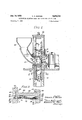
These and other objects and advantages of this invention will hereinafter appear and for purposes of illustration, but not of limitation, an embodiment of the invention is shown in the accompanying drawings in which-- Figure 1 is a sectional elevational view through a centrifugal abrasive throwing wheel embodying the features of this invention;
Figure 2 is an enlarged sectional elevational view taken along the line 22 of Figure 1;
Figure 3 is a perspective view of a blade and its latching means embodying the features of this invention;
Figure 4 is a sectional view taken along the line 4-4 of Figure 1;
Figure 5 is an elevational view of the throwing wheel separate and apart from the associated structure;
Figure 6 is a sectional view diametrically through the throwing wheel of Figure 5; and
Figure 7 is an enlarged elevational view of the latching means shown in Figures 1, 2 and 3 of the drawings.
Referring now to the drawings, a throwing wheel embodying the features of this invention comprises a rear side wall-forming disc member 10 and a front side wallforming disc member 12 which are secured one to the other in a predetermined spaced-apart relation by studs 14. The rear side wall-forming disc member 10 is secured by bolt members 16 to a hub 18 for rotational movement therewith. The hub 18 is secured onto the end portion of a driven shaft 20 for rotational movement at high speed therewith.
The numeral 22 represents an improved blade embodying the features of this invention, a plurality of which are mounted to extend crosswise between the front and rear side wall-forming disc members 10 and 12 generally in the radial direction with the outer edges of the blades reaching to about the periphery of the wheel while the inner sides terminate short of the axis about wh ich the Another 4 between. The upper portion of the bladed wheel is substantially completely enclosed within a stationary housing, indicated generally by the numeral 26. The area beneath the bladed wheel is usually open and it is through this area that the abrasive is usually thrown downwardly by the wheel onto the work.
Fitting into the opening 24 is a control cage in the form of a tubular member 28 having an annular flange 30 extending inwardly from the rearward end thereof while the forward end portion 32 extends beyond the front wallforming disc member 12 for engagement with the housing which supports the control cage stationarily within the opening. The control cage is provided with a discharge opening (not shown) in the periphery thereof through which abrasive particles fed into the control cage are projected onto the blades. The location of the discharge opening is adapted to be adjusted by turning movement of the control cage relative the housing thereby to provide directional control to the abrasive particles thrown from the wheel.
Mounted within the control cage is an impeller 34, preferably of the type described in the patent of Straub, No. 2,708,814, issued May 24, 1955. In the illustrated modification, the impeller is formed with a rear wheel 36, a plurality of vanes 38 extending forwardly from the rear wheel to a conically shaped lead-in section 40 which tapers outwardly from the feed end to the bladed section of the impeller. The impeller is secured by means of a bolt 42 to the end of the shaft 20 for rotational movement at high speed with the shaft.
A feed pipe 44 communicates the bottom end of a hopper 46 with the open end of the impeller for the delivery of abrasive material from the feed hopper onto the conical surface portion of the impeller. In operation, abrasive particles deposited upon the conical lead-in portion of the vaned impeller operate to impart rotational movement to the particles as they are advanced rearwardly over the conical surface to the bladed section so that the particles will flow smoothly into the bladed section where the blades operate to propel the abrasive material outwardly with considerable force through the discharge opening of the control cage and onto the inner ends of the blades or into the paths thereof.
The abrasive particles which are thrown by the impeller onto the inner ends of the blades gain considerable momentum as they move radially outwardly across the face of the blades to be thrown from the ends thereof with considerable force and velocity onto the surface to be treated. When the discharge opening in the control cage remains in the same position, the abrasive particles are thrown from the ends of the blades in a relatively uniform pattern which extends generally in the same direction. By adjusting the position of the discharge opening, as by rotational movement of the control cage, the direction of the abrasive pattern thrown from the wheel may be regulated and controlled, as pointed out in the patents previously referred to.
To the present, description has been made primarily of the general arrangement of elements in a centrifugal abrasive throwing wheel of the type which may be employed in the practice of this invention. The important concepts of this invention reside in the construction and arrangement of the throwing blades in the wheel and the means for locking the blades in position of use therein.
wheel rotates to define a cylindrical opening 24 ,there- 76 The throwing blades 22 embodying the features of this invention comprise elongate hardened metal members of rectangular shape having a relatively smooth top face 48 over which the abrasive particles travel from the inner end outwardly to be discharged centrifugally from the wheel. The thickness of the blade increases from the inner end 50 toward the outer end 52, as illustrated in Figure 4 of the drawings, to compensate for the increasing wear which takes place as the abrasive particles travel with increasing speed from the inner end to the outer end over the face of the blade.
The lateral edge portions of the blades are formed with integral upwardly and downwardly extending ribs or flanges 54, 56, 58 and 60, respectively, of substantially equal dimension to form blades which are generally H-shaped in cross-section. The ribbed lateral edge sections are dimensioned slidably to be received in fitting relation in facing radial slots 62 and 64 arranged in pairs in equally spaced-apart relation in the inner faces of the side wall-forming disc members and extending radially outwardly to the periphery of the disc members. The slots 62 and 64 are dimensioned to have a width corresponding to the thickness of the ribbed edge sections of the blades. The distance between the bases of the slots is adapted to correspond to the width of the blades. The slots are preferably formed to have a depth which is slightly less than the crosswise width of the ribbed sections so as to enable the blades to be retained in the slots with the blade portion 48 extending crosswise wholly between the disc members for passage of the abrasive particles over the face thereof in operation.
The lateral edges of the blades may be formed continuous as in previous construction but it is preferred to provide a plurality of recesses 66 in the lateral edges of the blades spaced inwardly from the forward and rear- Ward ends thereof to provide pads 68 therebetwecn which are received in fitting relation in the formed slots 62 and 64 to break up the air currents and to break up the channels through which abrasives may travel.
The use of a blade having spaced recesses or pockets of the type described otters a number of other important advantages over blade structures of the type heretofore employed. For example, in the event that an abrasive particle or particles become lodged within the confined space between the slot and the blade received therein in fitting relation, the abrasive particle or particles offers considerable resistance to the relative endwise movement of the blade for removal. When the blade is formed with a continuous edge, the particle or particles offer resistance as they are dragged throughout the length of the blade. On the other hand, when the blade has spaced pockets formed therein, the abrasive particle or particles can fall into the pocket after traveling only a fraction of the dis tance, thereby to eliminate further resistance to relative movement.
Another important advantage resides in the amount of machining required to fit the blade to the wheel. Where a continuous edge is present, as in the former structures, the entire edge is usually machined to the desired tolerance. When a blade embodying the preferred practice of this invention is employed, the machining required is greatly reduced since only the pads fit against the base of the slots. For this purpose, it is desirable to form the recesses of greater lengths than the pads therebetwecn to minimize the amount of machining that is required and to provide larger pockets in which movement of abrasive particles may be arrested thereby to minimize the possibilities of cutting the latching means in operation.
The new and novel concept for locking the blades in position of use in the slotted wheel disc members resides in the formation of crosswise aligned grooves 70 and 72, preferably of semi-circuiar section which extend laterally through an edge portion of the lips 54 and 56 extending outwardly from the bottom side of the blade. Similar recesses 74 and '76 are formed in the wheel disc members contiguous with the slots 62 and 64 to provide circular openings between the grooves 70 and 72 and the grooves '74 and 76 when the blade is in proper position of use in the wheel. Contiguous with the grooves 74 and 76 in the wheel disc members and axially aligned with the circular openings that are formed between the grooved blade and the wheel disc members are recesses or openings 78 and 80 which extend further outwardly into the wheel disc members but for a distance less than the thickfrom the groove.
When the blades are properly aligned in the wheel disc members, the grooves 70 and 72 in the blades are con tiguous with the grooves 74 and 76 in the edge of the slotted wheel disc members to provide a circular opening therebetwecn which is contiguous with the recesses 78 and 30 in the wheel. Adapted to be received within the aligned openings are a pair of head members 82 and 84 interconnected one with the other in a manner resiliently to urge .the head members outwardly into the openings. The head members are each formed with an inner cylindrical section 86 dimensioned to correspond to the crosssection of the circular openings that are formed between grooves 72 and 76 or between grooves 70 and 74. It is preferred to form the cylindrical section of the head to a thickness less than the width of the grooves '74 and 76. Extendingoutwardly from the cylindrical section is an integral section 88, preferably of conical shape, having a taper .at a lesser slope than that of the recesses 78 and in the wheel disc members for receiving the conical end section of the head members in a manner to position the cylindrical portions 86 within the aligned grooves of the blade and wheel disc members when the ends of the coni cal'section 88 come to rest against the walls of the recesses 78 and 80. It is preferred to form the grooved sections 70 and 72 in that portion of the ribs formed with pads and spaced inwardly from the ends of the blades, thereby to locate the locking means other than in one of the pocket sections where abrasive particles might be available to cut the head and thereby also to provide a greater area of contacting relationship between the head members and the blade firmly to lock the elements together. Various means may be employed for urging the heads 82 and 84 resiliently in the direction away from each other into sealing relation with the aligned openings. One such means, illustrated in the drawings, comprises a spring wire having a center portion formed into a loop 90 with end sections 92 and 94 extending linearly forwardly therefrom with cars 96 turned laterally in opposite directions onto which the headmembers 82 and 84 are fixed.
The loop 90 is dimensioned to have a diameter less than the distance between the spaced side wall-forming disc members 10 and 12 so as to be able to be housed therebetwecn. The head members 82 and 84 can be displaced inwardly by squeezing the forwardly extending end sections 92 and 94 to bring the ends of the conical section 84 into a spaced relation which is less than the distance between the wheel discs thereby to enable the looking means to be inserted endwise between the wheel members from the outer periphery of the wheel adjacent the underside of the blade until the head members 82 and 84 are substantially aligned with the openings formed by the grooves 70, 72, 74 and 76. Upon release of the spring member, the head sections will be urged outwardly in a direction away from each other to enter the openings and lock the blade in position of use.
The taper on the outer ends of the head members is effective, in operation, to cam the members into proper alignment for entrance of the heads into the grooved openings until the conical section seats firmly against the base of the recesses 78 and 80 in the wheel disc members. This positions the cylindrical portions 86 of the head members in the corresponding cylindrical opening formed between the ribbed portion of the blade and the wall of the slots 62 and 64 in the wheel disc members. The cylindrical section is formed to a lesser thickness than the receiving grooves and the conical section is formed to a taper less than the recess to enable entrance of the head members into the aligned grooves when released, since the head members will not have their axes in substantial alignment crosswise with the formed cylindrical openings and recesses until they are home in the openings. Until then, that is, while they are displaced inwardly from the cylindrical grooves for release of the blade, the head members will have their axes at a slight tilt with respect to the normal crosswise axis. If the cylindrical section of the head I 7 were of the same thickness as the width of the grooves, it would be difiicult to insert the heads or to remove the head members in the manner described.
In this connection also it is desirable to avoid a reverse taper in the cylindrical section or in the grooves because then the centrifugal forces operating during use of the wheel would tend to cam the head members out of the grooves. Thus the portion of the head member operatively engaged in the grooves is preferably formed cylindrical or with a taper which would earn the head into the recess rather than away therefrom in response to the radial centrifugal forces which exist in operation.
In operation, the blade is inserted endwise from the periphery of the wheel into the aligned slots with the portion 50 of lesser thickness forming the inner end portion of the blade. The blade is displaced inwardly through the slots until the semi-circular grooved portions 70 and 72 in the ribs of the blade are substantially aligned with the semi-circular grooves 74 and 76 contiguous with the slots. Then the latching means is squeezed by a suitable A tool for insertion endwise from the periphery of the wheel through the open space between the disc members along the backside of the blade until the head members are practically in alignment with the openings. As the spring is released, the head members are displaced laterally to enter into the aligned openings and for camming the blade into proper position within the slotted wheel sections. The head member continues to shift laterally through the aligned openings until the conical end section engages the side walls of the conical openings 78 and 80 within the Wheel disc member. Thus the cylindrical sections remain seated within the opening formed between the grooved rib of the blade and the grooved wheel disc member to prevent relative endwise displacement. As the wheel turns at high speed, the central portion of the spring interconnecting the head members is rotated about the heads at their centers to lie outwardly thereof adjacent the bottom side of the blade, as illustrated in Figure 3. Thus it is desirable to locate the interconnecting grooves inwardly from the edge of the blades and the wheel discs by an amount greater than the length of the latching means and preferably at about the mid-point of the blades.
For removal of a blade in replacement or repair, it is only necessary to insert a suitable tool through the opening beyond the spaced wheel disc members rearwardly of the blades to squeeze the spring arms 92 and 94 for withdrawal of the head sections from the aligned openings. Thus screw threads are completely eliminated. Removal or replacement of the blades can be effected easily and quickly without limitation as to the construction of the housing and of portions thereof. Further, no part of the locking means is in position to interfere with the operation of the machine and no parts are exposed for freezing the blades in the wheel or exposed for cutting off by abrasive particles traveling through channels while the equipment is in operation. Most important is the fact that less parts are removed to gain access to the locking means for removal of the blades or for reinsertion of blades, thereby to enable easy and quick removal or replacement of the blades so that operation can be effected without the expenditure of considerable time and effort and without the necessity to make use of highly skilled labor.
It will be apparent also from the description that the resilient means for securing the blades in the assembled relation by elements urged outwardly from areas between the ribbed sections of the blades operate in a manner which enables the blade to become located within the slotted portions of the wheel disc members to relieve stress conditions which otherwise might exist such as when setscrew members are forced laterally intonotches provided in the bladed sections for locking the blades in the wheel disc members, as in structures heretofore employed;
It will be understood that other means may be empl y d r sili nt y to e c nn ct the head members for urging the head members outwardly in the direction away from each other. For example, use may be made of telescoping members having the head members secured to the outer end portions thereof and wherein the spring members are spring urged in the direction. away from each other with means available in the telescoping members for establishing a gripping relation whereby they may be displaced inwardly in opposition to the spring members for withdrawal of the head sections from the openings.
While it is preferred to make use of the conical section extending inwardly, contiguously from the grooved slotted section of the side wall-forming disc members, elements which make use of the groove alone separate and apart from the conical recess may be employed to provide an opening with the slotted portion of the ribbed blade adapted to receive the head portion of the locking means. It will be further understood that the grooves formed in the slotted plates and in the ribbed blades may be other than semi-circular to form an opening therebetween adapted to receive a head having a cross-section corresponding to that of the slotted opening that is formed and that the recessed sections extending inwardly continuously from the grooves may be formed to shapes other than conical but which are preferably formed to have inclined walls and in which the outwardly extending end portion may be formed of other shapes but preferably to a similar shape but with a lesser slope.
It will be further understood that other changes may be made such as in the location of the grooves lengthwise in the blades and wheel and in the use of more than one pair of grooves and locking means per blade. Other changes in the details of construction and operation of the machine may be employed without departing from the spirit of the invention, especially as defined in the follow ing claims.
I claim:
1. In a centrifugal blasting wheel formed of a pair of spaced side wall forming disc members interconnected for rotational movement together and having pairs of facing slots extending radially inwardly from the periphery of the members and blades extending crosswise between the members and received in fitting relation within the slots, the improvement which comprises ribs extending downwardly from the lateral edges of the blades and which are received in the slots when in the assembled relation, crosswise aligned grooves in the bottom side of the ribs intermediate the ends thereof, crosswise aligned grooves in the portion of the wheel disc members forming the bottom Wall of the slots and positioned to be contiguous with the grooves in the ribs when the blade is in proper position for use to provide a continuous laterally extending opening therebetween, a pair of head members having a cross-section corresponding to the cross-section of the opening formed by the contiguous grooves for receiving the heads in fitting relation therein, and means constantly urging displacement of the head members laterally into the openings for locking the blades against relative endwise movement in the wheel disc members.
2. In a centrifugal blasting wheel formed of a pair of spaced side wall-forming disc members interconnected for rotational movement together and having pairs of facing slots extending laterally inwardly from the outer periphery of the members, and blades extending crosswise between the members and dimensioned to be received in fitting relation within the slots, the improvement which comprises ribs extending downwardly from the lateral edges of the blades and which are received in the slots when in the assembled relation, crosswise aligned grooves in the bottom side of the ribs intermediate the ends thereof, crosswise aligned grooves in the portion of the wheel disc members forming the bottom wall of the slots in position to be contiguous with the grooves in the ribs when the blade is in proper position for use to provide a continuous laterally extending opening therebetween, a recess extending into the wheel disc members continuously from the grooved slot and having its lower portion in alignment with the grooves and its upper portion in alignment with the grooves in the ribs of the blades when in the assembled relation to form a continuation of the opening therebetween, a pair of interconnected head members including a body portion corresponding in cross-section to the opening formed between the grooves and an end portion dimensioned to enter into the recess and to seat therein with the body portion in the opening thereby to locate the body portion in the opening formed by the grooves when the end portion is seated within the recess, and means constantly urging displacement of the head members laterally into the openings for locking the blades against relative endwise movement in the wheel disc members.
3. A centrifugal blasting wheel as claimed in claim 2 in which the grooves are semi-circular in cross-section to form a circular opening therebetween and in which the body portion of the head members is of cylindrical shape having a diameter corresponding to the diameter of the opening to be received therein a fitting relation.
4. A centrifugal blasting wheel as claimed in claim 2 in which the recess tapers inwardly from the end portion adjacent the grooves and in which the heads are formed with a tapered end portion of lesser inclination than the recess.
5. A centrifugal blasting wheel as claimed in claim 2 in which the grooves are semi-circular in cross-section to form a circular opening therebetween and in which the recesses are of conical shape having the axis in alignment with the axis of the circular opening formed by the grooves and in which the head members comprise a cylindrical section and a conical section extending outwardly integrally from the outer edge thereof with the body portion corresponding in cross-section to the aligned openings formed by the blade and slotted wheel disc members.
6. A centrifugal blasting wheel as claimed in claim 2 in which the head members are interconnected one with the other by means which resiliently urges the head members laterally in the direction away from each other.
7. A centrifugal blasting wheel as claimed in claim 6 in which the resilient means interconnecting the head members comprises a spring wire having a looped central portion and arms extending forwardly therefrom with ends turned laterally in the direction away from each other and on which the pairs of head members are mounted.
8. A centrifugal blasting wheel as claimed in claim 6 in which the grooves are spaced inwardly from the end of the blades and wheel disc members by an amount greater than the length of the interconnecting means.
9. A centrifugal blasting wheel as claimed in claim 2 in which the grooves are in the mid-portion between the ends of the blades.
10. A centrifugal blasting wheel as claimed in claim 1 in which the lateral edges of the blades are formed with a plurality of longitudinally spaced-apart recessed portions spaced inwardly from the ends to provide sepa rated pockets in which abrasive material may collect and to provide pads in between which break up the channels through which any abrasive and air can travel.
11. A centrifugal blasting wheel as claimed in claim 10 in which the ribbed portions are dimensioned to have a width greater than the depth of the slots in the wheel members.
12. A blade for use in a centrifugal blasting wheel having spaced side wall-forming disc members with pairs of facing slots extending radially inwardly from the outer periphery thereof and crosswise aligned grooves in the portions of the members defining the bottom wall of the slots, said blade having ribs extending upwardly and downwardly integrally from the lateral edges thereof to form upwardly and downwardly facing channel sections and in which the lateral edge portion of the blade is dimensioned to have a thickness corresponding to the width of the slots and a width greater than the distance between the spaced side wall-forming disc members and corresponding to the distance between the base of the crosswise aligned slots to receive the blades in fitting relation therein, and a pair of crosswise aligned grooves in the bottom edge of the downwardly extending ribs in position to be contiguous with the crosswise grooves in the slotted plates to form an opening therebetween when the blade is in proper position for use.
13. A blade for use in a centrifugal blasting wheel having spaced side wall-forming disc members with pairs of facing slots extending laterally inwardly from the outer periphery of the members and crosswise aligned grooves which are semi-circular in cross-section extending downwardly in the wall defining the bottom of the slots, said blade having ribs extending upwardly and downwardly integrally from the lateral edges thereof to form upwardly and downwardly facing channel sections, and a pair of crosswise aligned grooves of sernicircular cross-section in the bottom edge of the downwardly extending ribs in position to be contiguous with the grooves in the slotted members to form a circular opening therebetween when the blade is in proper position for use.
14. A blade as claimed in claim 12 in which the blade is formed with a plurality of longitudinally spaced apart recessed portions spaced inwardly from the ends to provide outwardly extending tabs in between and in which the grooves extend crosswise through one of the tab portions spaced inwardly from the ends of the blades.
References Cited in the file of this patent:
UNITED STATES PATENTS 2,170,832 Minich Aug. 29, 1939 2,204,633 Turnbull June 18, 1940 2,304,041 Unger Dec. 1, 1942 2,385,728 Potter Sept. 25, 1945 2,507,166 Lahman May 9, 1950
Priority Applications (1)
| Application Number | Priority Date | Filing Date | Title |
|---|---|---|---|
| US583135A US2819562A (en) | 1956-05-07 | 1956-05-07 | Centrifugal blasting wheel and blades for use in same |
Applications Claiming Priority (1)
| Application Number | Priority Date | Filing Date | Title |
|---|---|---|---|
| US583135A US2819562A (en) | 1956-05-07 | 1956-05-07 | Centrifugal blasting wheel and blades for use in same |
Publications (1)
| Publication Number | Publication Date |
|---|---|
| US2819562A true US2819562A (en) | 1958-01-14 |
Family
ID=24331817
Family Applications (1)
| Application Number | Title | Priority Date | Filing Date |
|---|---|---|---|
| US583135A Expired - Lifetime US2819562A (en) | 1956-05-07 | 1956-05-07 | Centrifugal blasting wheel and blades for use in same |
Country Status (1)
| Country | Link |
|---|---|
| US (1) | US2819562A (en) |
Cited By (24)
| Publication number | Priority date | Publication date | Assignee | Title |
|---|---|---|---|---|
| US2869289A (en) * | 1957-01-24 | 1959-01-20 | Pangborn Corp | Reversible centrifugal blasting method and apparatus |
| US3191346A (en) * | 1961-08-09 | 1965-06-29 | Pangborn Corp | Blasting wheel construction |
| US3290827A (en) * | 1962-04-27 | 1966-12-13 | Pangborn Corp | Particle throwing apparatus |
| US3352064A (en) * | 1965-02-01 | 1967-11-14 | Wheelabrator Corp | Lock system for blasting-machine blades |
| US3383804A (en) * | 1965-12-09 | 1968-05-21 | Pangborn Corp | Locking pin retainer for abrasive throwing blades |
| DE1296046B (en) * | 1964-10-03 | 1969-05-22 | Pangborn Corp | Cast impeller vane |
| US3513597A (en) * | 1965-02-01 | 1970-05-26 | Wheelabrator Corp | Locking blade for centrifugal blasting wheel |
| US3745711A (en) * | 1970-05-06 | 1973-07-17 | Wheelabrator Corp | Centrifugal blasting wheel and blade latching means |
| US3785105A (en) * | 1972-04-05 | 1974-01-15 | Wheelabrator Frye Inc | Centrifugal blasting wheel |
| JPS5110710B1 (en) * | 1971-06-18 | 1976-04-06 | ||
| US4227351A (en) * | 1978-04-17 | 1980-10-14 | Firma Maschinen Und Werkzeugfabrik Kabel Vogel & Schemmann | Centrifugal wheel assembly for spraying apparatus |
| US4249350A (en) * | 1979-01-15 | 1981-02-10 | Goff James R | Abrasive throwing wheel and improved blade assembly |
| US4277965A (en) * | 1977-11-24 | 1981-07-14 | Cockerill | Centrifugal shotting turbine |
| EP0094371A2 (en) * | 1982-04-26 | 1983-11-16 | Vereinigte Edelstahlwerke Aktiengesellschaft (Vew) | Method of making tempered blades for impeller wheels |
| US4447993A (en) * | 1982-04-16 | 1984-05-15 | Laido Donald A | Alignment means for centrifugal blasting wheel |
| US4480413A (en) * | 1979-09-24 | 1984-11-06 | Wheelabrator-Frye Inc. | Bladed centrifugal blasting wheel |
| WO1992000835A1 (en) * | 1990-07-06 | 1992-01-23 | Tilghman Wheelabrator Limited | Abrasive throwing wheel assemblies |
| WO2002028594A1 (en) * | 2000-10-02 | 2002-04-11 | Pangborn Corporation | Abrasive throwing wheel and improved blade assembly |
| US6447378B1 (en) | 2000-03-08 | 2002-09-10 | Disa Goff, Inc. | Abrasive throwing wheel and abrasive throwing blade |
| US20110117824A1 (en) * | 2009-11-16 | 2011-05-19 | Loutzenheiser Mathew Lynn | Vane, mounting assembly and throwing wheel apparatus having a locking member tapered in two planes |
| US8043141B1 (en) * | 2009-01-21 | 2011-10-25 | Goff James R | Throwing wheel assembly |
| US20130336770A1 (en) * | 2012-04-11 | 2013-12-19 | Straaltechniek International N.V./S.A. | Turbine |
| CN106425890A (en) * | 2016-12-08 | 2017-02-22 | 李广效 | Local shot blasting treatment device for surfaces of aluminum castings |
| KR101984062B1 (en) * | 2018-12-06 | 2019-06-04 | (주)대코 | A Method of Manufacturing the Blade for the Impeller of a Shot Peeing Machine and a Impeller Blade |
Citations (5)
| Publication number | Priority date | Publication date | Assignee | Title |
|---|---|---|---|---|
| US2170832A (en) * | 1934-05-25 | 1939-08-29 | American Foundry Equip Co | Abrasive throwing machine |
| US2204633A (en) * | 1936-11-17 | 1940-06-18 | American Foundry Equip Co | Abrasive-throwing wheel |
| US2304041A (en) * | 1940-07-12 | 1942-12-01 | American Foundry Equip Co | Centrifugal blasting machine |
| US2385728A (en) * | 1943-12-11 | 1945-09-25 | Pangborn Corp | Abrading apparatus |
| US2507166A (en) * | 1946-10-30 | 1950-05-09 | American Wheelabrator & Equipm | Directional control blasting wheel |
-
1956
- 1956-05-07 US US583135A patent/US2819562A/en not_active Expired - Lifetime
Patent Citations (5)
| Publication number | Priority date | Publication date | Assignee | Title |
|---|---|---|---|---|
| US2170832A (en) * | 1934-05-25 | 1939-08-29 | American Foundry Equip Co | Abrasive throwing machine |
| US2204633A (en) * | 1936-11-17 | 1940-06-18 | American Foundry Equip Co | Abrasive-throwing wheel |
| US2304041A (en) * | 1940-07-12 | 1942-12-01 | American Foundry Equip Co | Centrifugal blasting machine |
| US2385728A (en) * | 1943-12-11 | 1945-09-25 | Pangborn Corp | Abrading apparatus |
| US2507166A (en) * | 1946-10-30 | 1950-05-09 | American Wheelabrator & Equipm | Directional control blasting wheel |
Cited By (33)
| Publication number | Priority date | Publication date | Assignee | Title |
|---|---|---|---|---|
| US2869289A (en) * | 1957-01-24 | 1959-01-20 | Pangborn Corp | Reversible centrifugal blasting method and apparatus |
| US3191346A (en) * | 1961-08-09 | 1965-06-29 | Pangborn Corp | Blasting wheel construction |
| US3290827A (en) * | 1962-04-27 | 1966-12-13 | Pangborn Corp | Particle throwing apparatus |
| DE1296046B (en) * | 1964-10-03 | 1969-05-22 | Pangborn Corp | Cast impeller vane |
| US3513597A (en) * | 1965-02-01 | 1970-05-26 | Wheelabrator Corp | Locking blade for centrifugal blasting wheel |
| US3352064A (en) * | 1965-02-01 | 1967-11-14 | Wheelabrator Corp | Lock system for blasting-machine blades |
| US3383804A (en) * | 1965-12-09 | 1968-05-21 | Pangborn Corp | Locking pin retainer for abrasive throwing blades |
| US3745711A (en) * | 1970-05-06 | 1973-07-17 | Wheelabrator Corp | Centrifugal blasting wheel and blade latching means |
| JPS5110710B1 (en) * | 1971-06-18 | 1976-04-06 | ||
| US3785105A (en) * | 1972-04-05 | 1974-01-15 | Wheelabrator Frye Inc | Centrifugal blasting wheel |
| US4277965A (en) * | 1977-11-24 | 1981-07-14 | Cockerill | Centrifugal shotting turbine |
| US4227351A (en) * | 1978-04-17 | 1980-10-14 | Firma Maschinen Und Werkzeugfabrik Kabel Vogel & Schemmann | Centrifugal wheel assembly for spraying apparatus |
| US4249350A (en) * | 1979-01-15 | 1981-02-10 | Goff James R | Abrasive throwing wheel and improved blade assembly |
| US4480413A (en) * | 1979-09-24 | 1984-11-06 | Wheelabrator-Frye Inc. | Bladed centrifugal blasting wheel |
| US4447993A (en) * | 1982-04-16 | 1984-05-15 | Laido Donald A | Alignment means for centrifugal blasting wheel |
| EP0094371A3 (en) * | 1982-04-26 | 1986-07-02 | Vereinigte Edelstahlwerke Aktiengesellschaft (Vew) | Method of making tempered blades for impeller wheels |
| EP0094371A2 (en) * | 1982-04-26 | 1983-11-16 | Vereinigte Edelstahlwerke Aktiengesellschaft (Vew) | Method of making tempered blades for impeller wheels |
| WO1992000835A1 (en) * | 1990-07-06 | 1992-01-23 | Tilghman Wheelabrator Limited | Abrasive throwing wheel assemblies |
| GB2260722A (en) * | 1990-07-06 | 1993-04-28 | Tilghman Wheelabrator Ltd | Abrasive throwing wheel assemblies |
| GB2260722B (en) * | 1990-07-06 | 1995-01-18 | Tilghman Wheelabrator Ltd | Abrasive throwing wheel assemblies |
| US5577953A (en) * | 1990-07-06 | 1996-11-26 | Tilghman Wheelabrator Limited | Abrasive throwing wheel assemblies |
| US6447378B1 (en) | 2000-03-08 | 2002-09-10 | Disa Goff, Inc. | Abrasive throwing wheel and abrasive throwing blade |
| US7311584B2 (en) * | 2000-10-02 | 2007-12-25 | Pangborn Corporation | Abrasive throwing wheel and improved blade assembly |
| US20040166777A1 (en) * | 2000-10-02 | 2004-08-26 | Goff James R. | Abrasive throwing wheel and improved blade assembly |
| WO2002028594A1 (en) * | 2000-10-02 | 2002-04-11 | Pangborn Corporation | Abrasive throwing wheel and improved blade assembly |
| US8043141B1 (en) * | 2009-01-21 | 2011-10-25 | Goff James R | Throwing wheel assembly |
| US20110117824A1 (en) * | 2009-11-16 | 2011-05-19 | Loutzenheiser Mathew Lynn | Vane, mounting assembly and throwing wheel apparatus having a locking member tapered in two planes |
| US8550881B2 (en) | 2009-11-16 | 2013-10-08 | Pangborn Corporation | Vane, mounting assembly and throwing wheel apparatus having a locking member tapered in two planes |
| US20130336770A1 (en) * | 2012-04-11 | 2013-12-19 | Straaltechniek International N.V./S.A. | Turbine |
| US9206698B2 (en) * | 2012-04-11 | 2015-12-08 | Straaltechniek International N.V/S.A. | Turbine |
| CN106425890A (en) * | 2016-12-08 | 2017-02-22 | 李广效 | Local shot blasting treatment device for surfaces of aluminum castings |
| KR101984062B1 (en) * | 2018-12-06 | 2019-06-04 | (주)대코 | A Method of Manufacturing the Blade for the Impeller of a Shot Peeing Machine and a Impeller Blade |
| WO2020116730A1 (en) * | 2018-12-06 | 2020-06-11 | (주)대코 | Method for manufacturing blade for impeller of shot peening machine, and blade for impeller |
Similar Documents
| Publication | Publication Date | Title |
|---|---|---|
| US2819562A (en) | Centrifugal blasting wheel and blades for use in same | |
| EP0026996B1 (en) | Bladed centrifugal blasting wheel | |
| US3241266A (en) | Abrasive particle throwing wheel assembly | |
| US3785105A (en) | Centrifugal blasting wheel | |
| US4395851A (en) | Centrifugal abrasive blasting machine | |
| US3683556A (en) | Centrifugal blasting wheel | |
| US4249350A (en) | Abrasive throwing wheel and improved blade assembly | |
| EP0145104B1 (en) | An abrasive throwing wheel | |
| US3444651A (en) | Centrifuging wheel | |
| US4480413A (en) | Bladed centrifugal blasting wheel | |
| US2582702A (en) | Abrading apparatus | |
| US2708814A (en) | Centrifugal blasting wheel | |
| US2306847A (en) | Centrifugal abrasive throwing wheel | |
| EP1694465B1 (en) | Control cage for abrasive blast wheel | |
| US3867791A (en) | Abrasive blasting machine | |
| US3197920A (en) | Throwing wheel and parts therefor | |
| US6447378B1 (en) | Abrasive throwing wheel and abrasive throwing blade | |
| US4176502A (en) | Spacerless blasting wheel and blade locking arrangement therefor | |
| US4646483A (en) | Vanes for abrasive blasting wheels | |
| US7311584B2 (en) | Abrasive throwing wheel and improved blade assembly | |
| US2900765A (en) | Shot peening apparatus | |
| US2204634A (en) | Abrasive-throwing wheel | |
| EP0144215B1 (en) | Shot blasting wheel | |
| US4244150A (en) | One-piece abrasive blasting wheel | |
| US3290827A (en) | Particle throwing apparatus |