US2815825A - Cleaner and inlet air control - Google Patents
Cleaner and inlet air control Download PDFInfo
- Publication number
- US2815825A US2815825A US503210A US50321055A US2815825A US 2815825 A US2815825 A US 2815825A US 503210 A US503210 A US 503210A US 50321055 A US50321055 A US 50321055A US 2815825 A US2815825 A US 2815825A
- Authority
- US
- United States
- Prior art keywords
- cleaner
- air
- tube
- housing
- gasket
- Prior art date
- Legal status (The legal status is an assumption and is not a legal conclusion. Google has not performed a legal analysis and makes no representation as to the accuracy of the status listed.)
- Expired - Lifetime
Links
Images


Classifications
-
- B—PERFORMING OPERATIONS; TRANSPORTING
- B01—PHYSICAL OR CHEMICAL PROCESSES OR APPARATUS IN GENERAL
- B01D—SEPARATION
- B01D46/00—Filters or filtering processes specially modified for separating dispersed particles from gases or vapours
-
- F—MECHANICAL ENGINEERING; LIGHTING; HEATING; WEAPONS; BLASTING
- F02—COMBUSTION ENGINES; HOT-GAS OR COMBUSTION-PRODUCT ENGINE PLANTS
- F02M—SUPPLYING COMBUSTION ENGINES IN GENERAL WITH COMBUSTIBLE MIXTURES OR CONSTITUENTS THEREOF
- F02M35/00—Combustion-air cleaners, air intakes, intake silencers, or induction systems specially adapted for, or arranged on, internal-combustion engines
- F02M35/02—Air cleaners
- F02M35/026—Air cleaners acting by guiding the air over or through an oil or other liquid bath, e.g. combined with filters
Definitions
- Another object of my invention is a cleaner of" the abovetyp'e coristructed so that the efiicien'cy of the-cleaner 7
- Another ob ject o'f my"inv'entio'n is a liquid bath ain cleaner of the above' type constructedto effect more- ⁇ even distribution of the liquid throughout the filter medium "duriri'gi-normal operation.
- Another object of my. invention -'is new and improved moisture and wind guard or shield for the *leading' e'dge oft-the inlet of a hat type air cleaner.
- Another obj ect of my invention is a blast air guard or shield "ona hat”type cleaner of the above type which "is much cheapefthan previous guards or shields
- Another objedt ofmy invention is an' aircle'an'er us'able with an interrial combustion engine and adapted to be mounted onthecarburetor of the engineandconstructed so that vibration 'from'the carburetor will not be transmitted to' theb'odyof the cleaner.
- Another object of my'invention is amounting-tor a cleaner'of the above type which, while eifecting a positive connection between the" horn of the' carburetoran'cl the-body. of the--cleaner; nevertheless insulates the two withiespect to noise and vibration;
- Another'obiect of my invention is a cleaner of the above type-with a'centerpull-down stud for the filters'top cap and with meansto prevent undue 'flexing of the top cap and at the same time to eifect a'positive compression through the-various elements of the filter housing;
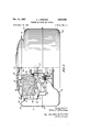
- Figure 1 is a side view; partly in section, of my'new and improved cleaner
- Figured is a top view-of the cleaner in Figure 1;
- Figure 3 is a bottom view of thecleaners top-cap
- FIG 4 is a sectional view of the mounting" gasket shownin Figure 1 but on-an'enlargedscale;
- Figure 5 isasectional'vieW of the 'gasketin Figure4'a's mounted? and Figure 6-is a -section taken on line 6 6 ;of' Figure :2.
- an air cleaner housing is indicated generally at 10 and is composed of annular air inlet 12 communicating with a liquid sump 14 by an air passage which extends through a suitable filter element or medium 16 to a clean air outlet 18.
- the housing includes a resonator or silencer chamber'20 composed generally of upper and lower housing members 22 and 24 and an inner housing member 26 joined by any suitable means to the upper housing member .22 and formed, in its lower region's, into the sump14 for a suitable'liquid, suchas oilor the like.
- The'inne'r ed ge ofthe inner housing extends inwardly from the sump" aim rises 'to a flanged edge 28'to provide a seat for suitable gasket 30.
- a center" tuning tube 32 is secured at its upper edge to the flange 28 by any suitable means and extends downwardly toward the clean air outlet.
- intermediate wall 34 divides the silencer chamber iiitotwocompartmaschineitsor sections and is secured atone e'fidat'3i6 to the inner'wa-ll 26 in any suitable manner and'attheothier' end at 38 to the center tuning tube.
- a large silencer chamber 41) is provided which extends'from the clean air outlet below the liquid sump and rises ar ou'nd' thefilte'r elemenflwhile
- a smaller silencer chamber 42 isprovide'd which'conforms generally to the liquid'silmp and"is"positioned' below it and opens into the center tiiniug tubeby a's'uit'able number of openings, for example four" in number, in the center tube.
- An dutentuning sleeve 46 is'positioned in spaced relationship around the' center tube :32 and, at its upper end conforms generally to'the inner wall of the resonator or silencer chamber an'd'is secured to the center tube at the sanie point, if' desired, asthe intermediate wall by any suitable means;
- Afilter'ghousin'g fits down into the depression or'cavity formedin'thesilencer chamber or housing and-includes an outer'vwall 52; an inner wall54, and atop capor cover 56;
- the inner wall is provided withan' abutment 58 which is opposed to and re'stsonthe" gasket30 and then extends outwardly into asuitably'bafiieformation 60 disposed in the sump below the normal liquid level.
- The" top cap 56' is 'composed o'fdouble' walls; with insulation or sound-deadening material at 62between 1 them, the top wall 64' extending outwardlyt-o'jointhe peripheral edge of the outer wall at 65 to define an outwardly facing; annular opening for the inlet passage.
- the lower wall 68 of the top cap is a spider-type structure having aplurality'of spokes 70as shown in Figure 3, and every other spoke and a plurality thereof having downwardly struck depending tabs 72 which are formed as an integral part of the spider structure and are punched from the (openings between the spokes.
- the tabs 72 are :generally'aligned with the inner wall 54 ofthe filter element, and when compression is applied to the top cap by a wing nut 74, center stud '76'which is secured to the center tube' 32? througha suitable cross bracket"78, the tabs 72', ine'fiect; function as'an intermediate supportto prevent undue fiexin'gof the top cap. They further transmit .the compression of the center stud through the inner wall of the filter housing to form a tight seal "with he gasket structure 30. V l
- the larger silencer or resonator chamber" 40 along its upperedge defines the outwardlyfacing annular inlet opening-6 with "the. peripheral edge '65 of the filter housing'.
- My cleaner is provided with a raised, rolled arcuat'e section 82 formed as an integral part of the silence:
- the horizontal tangent of this rolled section forms an upper edge 84 which is at least on a level with the peripheral edge 65 of the filter housing and may possibly be higher so that the inlet 66 in this area is effectively protected against the blast air.
- the outer tuning sleeve 46 is generally aligned with an outlet tube 86 which is suitably slotted for compres- S1011 by a clamp 88 which is adapted to be actuated in I the usual manner by a manually operable stud 89 as shown in Figure 2.
- the outer tuning sleeve and the outlet tube have opposed edges 90 and 92 respectively and are provided with outwardly extending flanges 94 and 96, respectively, which are disposed in spaced relationship.
- An annular gasket or insulation member is positioned between these two flanges and extends inwardly to an integral inner cylindrical portion 100 having a lower edge 102 adapted to resiliently abut the carburetor horn.
- the main body portion of the gasket extends outwardly to a cylindrical portion 104 which is disposed generally concentric with the inner portion 100 and is positioned beyond the extremity of the flange 96 on the outlet tube so as to overlie it.
- the flange 94 on the tuning sleeve is formed into a downward cylindrical portion 1% which surrounds portion 104 of the gasket and depends downwardly and is shaped into a retaining portion 108 which overlies and surrounds a locking portion 110 on the gasket.
- This locking portion is adapted normally to be disposed at approximately a 45 degree angle as shown in Figure 4 with relation to the main body portion 98 of the gasket.
- the lower portion 108 of the vsleeve is rolled or crimped inwardly to compress the gasket locking portion around the flange 96 on the outlet tube to efiect a rigid mounting.
- a liquid bath air cleaner of the hat type adapted to be mounted on the iaitake of a carburetor on an automobile engine or the
- Such engines are generally provided with a fan which is used to draw air through a radiator for cooling and removing the heat from the cooling fluid for the engine.
- a fan creates a strong current of air which, if allowed to hit the outwardly disposed radial annular inlet for the air cleaner, will force all of the liquid out of the sump and filter medium on the side toward the fan.
- the velocity head of the air will be converted to static head creating a pressure difierential across the circumferential opening of the air cleaner. For example, this pressure differential causes spill-over of oil and poor efiiciency.
- all of the liquid in the sump under the baifle 60 could normally be blown out of the sump into the filter and a large portion of the liquid would be carried over from the filter medium into the carburetor and into the engine.
- the shield does in no way hinder the admission of air into the cleaner as it is spaced laterally a distance equal to the normal inlet opening 66.
- the shield is formed as an integral part of or an extension of the silencer chamber that surrounds the pullover property of the cleaner will be greatly improved.
- the shield is formed as an integral part of the main housing during the same drawing operation does not require any separate pieces or parts which have to be attached during manufacture and it cannot come loose or be damaged in any unnormal way.
- the volume of the silencer chamber is increased without increasing the space taken up by the cleaner under the hood of the automobile.
- the top cap of the filter element is provided with a plurality of depending downwardly struck tabs which, during manufacture, are cut as an integral part of the lower wall of the top cap and are bent approximately at degrees so as to oppose the inner wall of the filter element.
- these tabs prevent undue flexing and support the top cap, and at the same time they transmit the compression of the center stud through the filter element or housing to the sealing gasket between the housing and filter unit.
- These depending tabs are made as an integral part of the cap and when the spider element that holds the silencing mat in position is stamped, the tabs are merely cut from the material that forms the spokes of the spider element. This efiects a substantial saving in the amount of material needed, the tabs are integral with the top cap, and an unnecessary step generally required to secure separate tabs in position on the top cap is eliminated.
- the cleaner housing be rigidly mounted on the intake horn of the carburetor, but at the same time it is desirable that these two elements be insulated or gasketed from each other so that vibration and noise will not be transmitted directly from the carelement has a cylindrical member which has an abutting edge adapted to oppose and engage the inlet of the carburetor.
- the outer edge of the gasket element overlies the flange of the outlet tube and has a portion adapted to overlie and surround it and to be locked into position around it when the outer cylindrical portion of the tuning tube is rolled around it.
- the tube that is adapted to be mounted on the carburetor is locked positively through the gasket to the center tuning tube which thus efiects a positive connection between the filter housing, the structure forming the liquid sump and the silencer chamber structure.
- a single gasket element performs these functions: It insulates the carburetor mounting tube from the tuning tube above it. It forms a positive connection between the carburetor mounting tube and the silencer housing. It forms a cushion seat for the inlet horn of the carburetor. And it secures the silencer chamber and the carburetor mounting tube to the sump structure and, indirectly, to the filter housing.
- a housing having a dirty air inlet and a clean air outlet with an air passage between them and a filter medium therein, a tube in the center Of the housing forming the clean air outlet with a silencer chamber in the housing around the tube, the tube including two generally aligned but non-contacting portions, one above the other, and having opposed edges, the lower portion being adapted to be mounted on the intake of a carburetor, the opposed edges having outwardly extending spaced flanges, and a gasket element between the flanges preventing metal-to-metal contact, the gasket element having an outer portion which overlies and surrounds the end of the flange on one of the tube portions, the flange on the other tube portion having an extension surrounding the outer portion of the gasket and flange.
Description
Dec. 10, 1957 J. J. DREZNES 2,815,825
C L EANER AND INLETD AIR CONTROL Filed April 22, 1955 3 Sheets-Sheet 1 N C N 172062507" J5n J'firezn es Dec. 10, 1957 J. J. DREZNES 2,815,325
CLEANER AND INLET AIR CONTROL Filed April 22, 1955 v s Sheets-Sheet 2 I7? ven for Jlzn I fir'eznesj'rr'i'erfi Carier .lzlarizegqs Dec. 10, 1957 J. J. DREZNES CLEANER AND INLET AIR common Filed April 22. 1955 3 Sheets-Sheet 3 Fly 4 Z W. 6 mz am e X0 WM If a W J United, rates Patent CLEANER AND INLET AIR CUNTROL Joliii'JQjfii-e'zn'es, Chicago, 111., assignor a United Specialtis' company; Chicago; Ill., a corporation of Delaware Application April 22, 1955, Serial Not-503,210 3' Claims. (21. rea -43 This invenaen reside in thefield or air' earers or the type generally usable' with air-consuming devices, suh" as internal combustion engines; although it' isnot necessarilyrestricted inthis' respect, and such' a cleaner is: generally referred" to as a'hat type liquid bath air conventional operation from the cleaners filter medium ifito' the carburetor and'th'e engine.
Another object of my invention is a cleaner of" the abovetyp'e coristructed so that the efiicien'cy of the-cleaner 7 Another ob ject o'f my"inv'entio'n isa liquid bath ain cleaner of the above' type constructedto effect more-{even distribution of the liquid throughout the filter medium "duriri'gi-normal operation.
Another object of my. invention -'is new and improved moisture and wind guard or shield for the *leading' e'dge oft-the inlet of a hat type air cleaner.
Another obj ect of my invention 'is a blast air guard or shield "ona hat "type cleaner of the above type which "is much cheapefthan previous guards or shields Another objedt ofmy invention is an' aircle'an'er us'able with an interrial combustion engine and adapted to be mounted onthecarburetor of the engineandconstructed so that vibration 'from'the carburetor will not be transmitted to' theb'odyof the cleaner.
Another object of my'invention is amounting-tor a cleaner'of the above type which, while eifecting a positive connection between the" horn of the' carburetoran'cl the-body. of the--cleaner; nevertheless insulates the two withiespect to noise and vibration;
Another'obiect of my invention is a cleaner of the above type-with a'centerpull-down stud for the filters'top cap and with meansto prevent undue 'flexing of the top cap and at the same time to eifect a'positive compression through the-various elements of the filter housing;
Other"objects---w-i1l appear from timeto time in the ensuing specification' and drawings in which:
Figure 1 is a side view; partly in section, of my'new and improved cleaner;
Figured is a top view-of the cleaner inFigure 1;
Figure 3 is a bottom view of thecleaners top-cap;
Figure 4 is a sectional view of the mounting" gasket shownin Figure 1 but on-an'enlargedscale;
Figure 5 isasectional'vieW of the 'gasketin Figure4'a's mounted? and Figure 6-is a -section taken on line 6 6 ;of' Figure :2.
In Figure 1 an air cleaner housing is indicated generally at 10 and is composed of annular air inlet 12 communicating with a liquid sump 14 by an air passage which extends through a suitable filter element or medium 16 to a clean air outlet 18. The housing includes a resonator or silencer chamber'20 composed generally of upper and lower housing members 22 and 24 and an inner housing member 26 joined by any suitable means to the upper housing member .22 and formed, in its lower region's, into the sump14 for a suitable'liquid, suchas oilor the like. The'inne'r ed ge ofthe inner housing extends inwardly from the sump" aim rises 'to a flanged edge 28'to provide a seat for suitable gasket 30. A center" tuning tube 32 is secured at its upper edge to the flange 28 by any suitable means and extends downwardly toward the clean air outlet.
Afilter'ghousin'g 'fits down into the depression or'cavity formedin'thesilencer chamber or housing and-includes an outer'vwall 52; an inner wall54, and atop capor cover 56; The inner wall is provided withan' abutment 58 which is opposed to and re'stsonthe" gasket30 and then extends outwardly into asuitably'bafiieformation 60 disposed in the sump below the normal liquid level. The" top cap 56' is 'composed o'fdouble' walls; with insulation or sound-deadening material at 62between 1 them, the top wall 64' extending outwardlyt-o'jointhe peripheral edge of the outer wall at 65 to define an outwardly facing; annular opening for the inlet passage. The lower wall 68 of the top cap is a spider-type structure having aplurality'of spokes 70as shown in Figure 3, and every other spoke and a plurality thereof having downwardly struck depending tabs 72 which are formed as an integral part of the spider structure and are punched from the (openings between the spokes. The tabs 72 are :generally'aligned with the inner wall 54 ofthe filter element, and when compression is applied to the top cap by a wing nut 74, center stud '76'which is secured to the center tube' 32? througha suitable cross bracket"78, the tabs 72', ine'fiect; function as'an intermediate supportto prevent undue fiexin'gof the top cap. They further transmit .the compression of the center stud through the inner wall of the filter housing to form a tight seal "with he gasket structure 30. V l
The larger silencer or resonator chamber" 40 along its upperedge defines the outwardlyfacing annular inlet opening-6 with "the. peripheral edge '65 of the filter housing'. When the cleaner is positioned securely .on the intake .horn of a carburetor, one side or portion of the housing will be positioned forward and will receive high velocityblast vair from the cooling fan generally used with an automotive engine. The arrow in .Figure 2 indicates generally the direction of this blast air.
My cleaner is provided with a raised, rolled arcuat'e section 82 formed as an integral part of the silence:
filter medium and liquid sump. Thus the etficiency and should extend approximately 55 degrees on each side of the center line of the incoming air to effect an arcuate baflie or shield of approximately 110 degrees. As shown in Figure l, the horizontal tangent of this rolled section forms an upper edge 84 which is at least on a level with the peripheral edge 65 of the filter housing and may possibly be higher so that the inlet 66 in this area is effectively protected against the blast air.
The outer tuning sleeve 46 is generally aligned with an outlet tube 86 which is suitably slotted for compres- S1011 by a clamp 88 which is adapted to be actuated in I the usual manner by a manually operable stud 89 as shown in Figure 2. The outer tuning sleeve and the outlet tube have opposed edges 90 and 92 respectively and are provided with outwardly extending flanges 94 and 96, respectively, which are disposed in spaced relationship. An annular gasket or insulation member is positioned between these two flanges and extends inwardly to an integral inner cylindrical portion 100 having a lower edge 102 adapted to resiliently abut the carburetor horn. The main body portion of the gasket extends outwardly to a cylindrical portion 104 which is disposed generally concentric with the inner portion 100 and is positioned beyond the extremity of the flange 96 on the outlet tube so as to overlie it. The flange 94 on the tuning sleeve is formed into a downward cylindrical portion 1% which surrounds portion 104 of the gasket and depends downwardly and is shaped into a retaining portion 108 which overlies and surrounds a locking portion 110 on the gasket.
This locking portion is adapted normally to be disposed at approximately a 45 degree angle as shown in Figure 4 with relation to the main body portion 98 of the gasket. However, the lower portion 108 of the vsleeve is rolled or crimped inwardly to compress the gasket locking portion around the flange 96 on the outlet tube to efiect a rigid mounting.
The use, operation and function of my invention are as follows:
I provide what is generally termed a liquid bath air cleaner of the hat type adapted to be mounted on the iaitake of a carburetor on an automobile engine or the Such engines are generally provided with a fan which is used to draw air through a radiator for cooling and removing the heat from the cooling fluid for the engine. Such a fan creates a strong current of air which, if allowed to hit the outwardly disposed radial annular inlet for the air cleaner, will force all of the liquid out of the sump and filter medium on the side toward the fan. The velocity head of the air will be converted to static head creating a pressure difierential across the circumferential opening of the air cleaner. For example, this pressure differential causes spill-over of oil and poor efiiciency. For example in Figure 1 all of the liquid in the sump under the baifle 60 could normally be blown out of the sump into the filter and a large portion of the liquid would be carried over from the filter medium into the carburetor and into the engine.
To prevent this I provide a raised blast shield which extends a substantial arcuate distance around the outwardly disposed inlet to protect it. At the same time any moisture, such as rain or the like, is also blocked from the inlet. The shield does in no way hinder the admission of air into the cleaner as it is spaced laterally a distance equal to the normal inlet opening 66. Furthermore the shield is formed as an integral part of or an extension of the silencer chamber that surrounds the pullover property of the cleaner will be greatly improved. At the same time the shield is formed as an integral part of the main housing during the same drawing operation does not require any separate pieces or parts which have to be attached during manufacture and it cannot come loose or be damaged in any unnormal way. At the same time the volume of the silencer chamber is increased without increasing the space taken up by the cleaner under the hood of the automobile.
The top cap of the filter element is provided with a plurality of depending downwardly struck tabs which, during manufacture, are cut as an integral part of the lower wall of the top cap and are bent approximately at degrees so as to oppose the inner wall of the filter element. During the compression effected by the center stud, these tabs prevent undue flexing and support the top cap, and at the same time they transmit the compression of the center stud through the filter element or housing to the sealing gasket between the housing and filter unit. These depending tabs are made as an integral part of the cap and when the spider element that holds the silencing mat in position is stamped, the tabs are merely cut from the material that forms the spokes of the spider element. This efiects a substantial saving in the amount of material needed, the tabs are integral with the top cap, and an unnecessary step generally required to secure separate tabs in position on the top cap is eliminated.
It is very desirable that the cleaner housing be rigidly mounted on the intake horn of the carburetor, but at the same time it is desirable that these two elements be insulated or gasketed from each other so that vibration and noise will not be transmitted directly from the carelement has a cylindrical member which has an abutting edge adapted to oppose and engage the inlet of the carburetor. The outer edge of the gasket element overlies the flange of the outlet tube and has a portion adapted to overlie and surround it and to be locked into position around it when the outer cylindrical portion of the tuning tube is rolled around it. Thus the two tubes, even though completely separated at all points, nevertheless are interlocked and a positive mechanical connection is provided between the cleaner housing and the tube adapted to be mounted on the carburetor. Furthermore, the tube that is adapted to be mounted on the carburetor is locked positively through the gasket to the center tuning tube which thus efiects a positive connection between the filter housing, the structure forming the liquid sump and the silencer chamber structure. It should also be noted that a single gasket element performs these functions: It insulates the carburetor mounting tube from the tuning tube above it. It forms a positive connection between the carburetor mounting tube and the silencer housing. It forms a cushion seat for the inlet horn of the carburetor. And it secures the silencer chamber and the carburetor mounting tube to the sump structure and, indirectly, to the filter housing.
While I have shown and described a preferred form of my invention, nevertheless many changes may be made in the size, shape, number and disposition of parts without departing from the spirit of my invention. I, therefore, wish my description and drawings to be taken as in a broad sense illustrative or diagrammatic, rather than as limiting me to my precise showing.
I claim:
1. In an air cleaner, a housing having a dirty air inlet and a clean air outlet with an air passage between them and a filter medium therein, a tube in the center Of the housing forming the clean air outlet with a silencer chamber in the housing around the tube, the tube including two generally aligned but non-contacting portions, one above the other, and having opposed edges, the lower portion being adapted to be mounted on the intake of a carburetor, the opposed edges having outwardly extending spaced flanges, and a gasket element between the flanges preventing metal-to-metal contact, the gasket element having an outer portion which overlies and surrounds the end of the flange on one of the tube portions, the flange on the other tube portion having an extension surrounding the outer portion of the gasket and flange.
2. The structure of claim 1 in which the gasket element has an annular portion disposed inwardly of the tube adapted to engage the carburetor.
References Cited in the file of this patent UNITED STATES PATENTS 2,126,643 Karnrath Aug. 9, 1938 2,557,237 Sebok June 19, 1951 2,601,172 Sebok June 17, 1952 2,690,233 Dreznes Sept. 28, 1954 2,691,426 Sebok et a1. Oct. 12, 1954 2,725,116 Spahr Nov. 29, 1955
Priority Applications (1)
| Application Number | Priority Date | Filing Date | Title |
|---|---|---|---|
| US503210A US2815825A (en) | 1955-04-22 | 1955-04-22 | Cleaner and inlet air control |
Applications Claiming Priority (1)
| Application Number | Priority Date | Filing Date | Title |
|---|---|---|---|
| US503210A US2815825A (en) | 1955-04-22 | 1955-04-22 | Cleaner and inlet air control |
Publications (1)
| Publication Number | Publication Date |
|---|---|
| US2815825A true US2815825A (en) | 1957-12-10 |
Family
ID=24001162
Family Applications (1)
| Application Number | Title | Priority Date | Filing Date |
|---|---|---|---|
| US503210A Expired - Lifetime US2815825A (en) | 1955-04-22 | 1955-04-22 | Cleaner and inlet air control |
Country Status (1)
| Country | Link |
|---|---|
| US (1) | US2815825A (en) |
Cited By (3)
| Publication number | Priority date | Publication date | Assignee | Title |
|---|---|---|---|---|
| US20040065206A1 (en) * | 2002-10-04 | 2004-04-08 | Walker Robert A. | Air filter assembly |
| US20130167727A1 (en) * | 2011-12-30 | 2013-07-04 | Walker Engineering | Air filter and silencer |
| WO2017156225A1 (en) * | 2016-03-09 | 2017-09-14 | K&N Engineering, Inc. | Air filter for turbochargers and superchargers |
Citations (6)
| Publication number | Priority date | Publication date | Assignee | Title |
|---|---|---|---|---|
| US2126643A (en) * | 1936-09-12 | 1938-08-09 | Gen Motors Corp | Air cleaner and silencer assembly |
| US2557237A (en) * | 1948-12-23 | 1951-06-19 | Houdaille Hershey Corp | Air cleaner and intake silencer and outlet assembly therefor |
| US2601172A (en) * | 1949-03-31 | 1952-06-17 | Houdaille Hershey Corp | Shock absorbing and silencing mounting arrangement for air cleaners |
| US2690233A (en) * | 1950-09-15 | 1954-09-28 | United Specialties Co | Combination air cleaner and silencer |
| US2691426A (en) * | 1952-07-19 | 1954-10-12 | Houdaille Hershey Corp | Air cleaner and intake silencer unit |
| US2725116A (en) * | 1951-11-28 | 1955-11-29 | Gen Motors Corp | Air cleaner retainer |
-
1955
- 1955-04-22 US US503210A patent/US2815825A/en not_active Expired - Lifetime
Patent Citations (6)
| Publication number | Priority date | Publication date | Assignee | Title |
|---|---|---|---|---|
| US2126643A (en) * | 1936-09-12 | 1938-08-09 | Gen Motors Corp | Air cleaner and silencer assembly |
| US2557237A (en) * | 1948-12-23 | 1951-06-19 | Houdaille Hershey Corp | Air cleaner and intake silencer and outlet assembly therefor |
| US2601172A (en) * | 1949-03-31 | 1952-06-17 | Houdaille Hershey Corp | Shock absorbing and silencing mounting arrangement for air cleaners |
| US2690233A (en) * | 1950-09-15 | 1954-09-28 | United Specialties Co | Combination air cleaner and silencer |
| US2725116A (en) * | 1951-11-28 | 1955-11-29 | Gen Motors Corp | Air cleaner retainer |
| US2691426A (en) * | 1952-07-19 | 1954-10-12 | Houdaille Hershey Corp | Air cleaner and intake silencer unit |
Cited By (12)
| Publication number | Priority date | Publication date | Assignee | Title |
|---|---|---|---|---|
| US20040065206A1 (en) * | 2002-10-04 | 2004-04-08 | Walker Robert A. | Air filter assembly |
| US6726738B1 (en) * | 2002-10-04 | 2004-04-27 | Robert A. Walker, Jr. | Air filter assembly |
| US20130167727A1 (en) * | 2011-12-30 | 2013-07-04 | Walker Engineering | Air filter and silencer |
| US9611822B2 (en) * | 2011-12-30 | 2017-04-04 | Walker Design, Inc. | Air filter and silencer |
| WO2017156225A1 (en) * | 2016-03-09 | 2017-09-14 | K&N Engineering, Inc. | Air filter for turbochargers and superchargers |
| KR20180134883A (en) * | 2016-03-09 | 2018-12-19 | 케이앤드엔 엔지니어링, 인크. | Air filters for turbochargers and superchargers |
| CN109642524A (en) * | 2016-03-09 | 2019-04-16 | K&N工程公司 | Air filter for turbocharger and mechanical supercharger |
| US10473066B2 (en) | 2016-03-09 | 2019-11-12 | K&N Engineering, Inc. | Air filter for turbochargers and superchargers |
| CN109642524B (en) * | 2016-03-09 | 2021-05-07 | K&N工程公司 | Air filter for turbochargers and superchargers |
| US11092120B2 (en) | 2016-03-09 | 2021-08-17 | K&N Engineering, Inc. | Air filter for turbochargers and superchargers |
| KR102304794B1 (en) | 2016-03-09 | 2021-09-27 | 케이앤드엔 엔지니어링, 인크. | Air filters for turbochargers and superchargers |
| AU2017229761B2 (en) * | 2016-03-09 | 2022-03-10 | K&N Engineering, Inc. | Air filter for turbochargers and superchargers |
Similar Documents
| Publication | Publication Date | Title |
|---|---|---|
| US3249172A (en) | Automotive vehicle hood, intake silencer, and filter | |
| US10532304B2 (en) | Interface air filter and assembly | |
| US4236901A (en) | Air cleaner with secondary air filter element | |
| US2869670A (en) | Intake silencer | |
| US3002585A (en) | Rotary air screen | |
| US4198217A (en) | Protective air filter intake hood with air deflecting intake screen | |
| US2996145A (en) | Filter sealing means | |
| US2954091A (en) | Cleaner silencer assembly | |
| US2815825A (en) | Cleaner and inlet air control | |
| US2553326A (en) | Apparatus for silencing and filtering noise producing gases | |
| US3186391A (en) | Crankcase ventilation | |
| US3737002A (en) | Suction gas protective device in motor vehicle | |
| US2385814A (en) | Air cleaner and silencer assembly | |
| US2795928A (en) | Arrangement of component elements of a gas turbine power plant | |
| US3039254A (en) | Air cleaner and silencer assembly | |
| US2465846A (en) | Hood structure for aircraft engine turbosuperchargers | |
| US1532473A (en) | Exhaust fire screen | |
| US2243866A (en) | Intake silencer and air cleaner | |
| US5666805A (en) | Emission control system for internal-combustion engines | |
| US2243083A (en) | Air cleaner and silencer assembly | |
| US2126643A (en) | Air cleaner and silencer assembly | |
| US4433541A (en) | Secondary air introducing apparatus for internal combustion engine | |
| US2906370A (en) | Air cleaner and silencer assembly | |
| US2865467A (en) | Cleaner silencer assembly | |
| US3473301A (en) | Air filter assemblies for internal combustion engines |