US2813402A - Apparatus for liquid filling of pressure storage tanks - Google Patents
Apparatus for liquid filling of pressure storage tanks Download PDFInfo
- Publication number
- US2813402A US2813402A US527522A US52752255A US2813402A US 2813402 A US2813402 A US 2813402A US 527522 A US527522 A US 527522A US 52752255 A US52752255 A US 52752255A US 2813402 A US2813402 A US 2813402A
- Authority
- US
- United States
- Prior art keywords
- valve
- tank
- vapor
- liquid
- pressure
- Prior art date
- Legal status (The legal status is an assumption and is not a legal conclusion. Google has not performed a legal analysis and makes no representation as to the accuracy of the status listed.)
- Expired - Lifetime
Links
Images

Classifications
-
- F—MECHANICAL ENGINEERING; LIGHTING; HEATING; WEAPONS; BLASTING
- F16—ENGINEERING ELEMENTS AND UNITS; GENERAL MEASURES FOR PRODUCING AND MAINTAINING EFFECTIVE FUNCTIONING OF MACHINES OR INSTALLATIONS; THERMAL INSULATION IN GENERAL
- F16K—VALVES; TAPS; COCKS; ACTUATING-FLOATS; DEVICES FOR VENTING OR AERATING
- F16K1/00—Lift valves or globe valves, i.e. cut-off apparatus with closure members having at least a component of their opening and closing motion perpendicular to the closing faces
- F16K1/30—Lift valves or globe valves, i.e. cut-off apparatus with closure members having at least a component of their opening and closing motion perpendicular to the closing faces specially adapted for pressure containers
- F16K1/304—Shut-off valves with additional means
- F16K1/305—Shut-off valves with additional means with valve member and actuator on the same side of the seat
-
- F—MECHANICAL ENGINEERING; LIGHTING; HEATING; WEAPONS; BLASTING
- F16—ENGINEERING ELEMENTS AND UNITS; GENERAL MEASURES FOR PRODUCING AND MAINTAINING EFFECTIVE FUNCTIONING OF MACHINES OR INSTALLATIONS; THERMAL INSULATION IN GENERAL
- F16K—VALVES; TAPS; COCKS; ACTUATING-FLOATS; DEVICES FOR VENTING OR AERATING
- F16K1/00—Lift valves or globe valves, i.e. cut-off apparatus with closure members having at least a component of their opening and closing motion perpendicular to the closing faces
- F16K1/30—Lift valves or globe valves, i.e. cut-off apparatus with closure members having at least a component of their opening and closing motion perpendicular to the closing faces specially adapted for pressure containers
- F16K1/304—Shut-off valves with additional means
- F16K1/306—Shut-off valves with additional means with a valve member, e.g. stem or shaft, passing through the seat
-
- F—MECHANICAL ENGINEERING; LIGHTING; HEATING; WEAPONS; BLASTING
- F16—ENGINEERING ELEMENTS AND UNITS; GENERAL MEASURES FOR PRODUCING AND MAINTAINING EFFECTIVE FUNCTIONING OF MACHINES OR INSTALLATIONS; THERMAL INSULATION IN GENERAL
- F16K—VALVES; TAPS; COCKS; ACTUATING-FLOATS; DEVICES FOR VENTING OR AERATING
- F16K15/00—Check valves
- F16K15/02—Check valves with guided rigid valve members
- F16K15/06—Check valves with guided rigid valve members with guided stems
- F16K15/063—Check valves with guided rigid valve members with guided stems the valve being loaded by a spring
- F16K15/066—Check valves with guided rigid valve members with guided stems the valve being loaded by a spring with a plurality of valve members
-
- Y—GENERAL TAGGING OF NEW TECHNOLOGICAL DEVELOPMENTS; GENERAL TAGGING OF CROSS-SECTIONAL TECHNOLOGIES SPANNING OVER SEVERAL SECTIONS OF THE IPC; TECHNICAL SUBJECTS COVERED BY FORMER USPC CROSS-REFERENCE ART COLLECTIONS [XRACs] AND DIGESTS
- Y10—TECHNICAL SUBJECTS COVERED BY FORMER USPC
- Y10T—TECHNICAL SUBJECTS COVERED BY FORMER US CLASSIFICATION
- Y10T137/00—Fluid handling
- Y10T137/2496—Self-proportioning or correlating systems
- Y10T137/2544—Supply and exhaust type
-
- Y—GENERAL TAGGING OF NEW TECHNOLOGICAL DEVELOPMENTS; GENERAL TAGGING OF CROSS-SECTIONAL TECHNOLOGIES SPANNING OVER SEVERAL SECTIONS OF THE IPC; TECHNICAL SUBJECTS COVERED BY FORMER USPC CROSS-REFERENCE ART COLLECTIONS [XRACs] AND DIGESTS
- Y10—TECHNICAL SUBJECTS COVERED BY FORMER USPC
- Y10T—TECHNICAL SUBJECTS COVERED BY FORMER US CLASSIFICATION
- Y10T137/00—Fluid handling
- Y10T137/2496—Self-proportioning or correlating systems
- Y10T137/2559—Self-controlled branched flow systems
-
- Y—GENERAL TAGGING OF NEW TECHNOLOGICAL DEVELOPMENTS; GENERAL TAGGING OF CROSS-SECTIONAL TECHNOLOGIES SPANNING OVER SEVERAL SECTIONS OF THE IPC; TECHNICAL SUBJECTS COVERED BY FORMER USPC CROSS-REFERENCE ART COLLECTIONS [XRACs] AND DIGESTS
- Y10—TECHNICAL SUBJECTS COVERED BY FORMER USPC
- Y10T—TECHNICAL SUBJECTS COVERED BY FORMER US CLASSIFICATION
- Y10T137/00—Fluid handling
- Y10T137/7722—Line condition change responsive valves
- Y10T137/7771—Bi-directional flow valves
- Y10T137/7772—One head and seat carried by head of another
- Y10T137/7777—Both valves spring biased
-
- Y—GENERAL TAGGING OF NEW TECHNOLOGICAL DEVELOPMENTS; GENERAL TAGGING OF CROSS-SECTIONAL TECHNOLOGIES SPANNING OVER SEVERAL SECTIONS OF THE IPC; TECHNICAL SUBJECTS COVERED BY FORMER USPC CROSS-REFERENCE ART COLLECTIONS [XRACs] AND DIGESTS
- Y10—TECHNICAL SUBJECTS COVERED BY FORMER USPC
- Y10T—TECHNICAL SUBJECTS COVERED BY FORMER US CLASSIFICATION
- Y10T137/00—Fluid handling
- Y10T137/7722—Line condition change responsive valves
- Y10T137/7771—Bi-directional flow valves
- Y10T137/7778—Axes of ports perpendicular
-
- Y—GENERAL TAGGING OF NEW TECHNOLOGICAL DEVELOPMENTS; GENERAL TAGGING OF CROSS-SECTIONAL TECHNOLOGIES SPANNING OVER SEVERAL SECTIONS OF THE IPC; TECHNICAL SUBJECTS COVERED BY FORMER USPC CROSS-REFERENCE ART COLLECTIONS [XRACs] AND DIGESTS
- Y10—TECHNICAL SUBJECTS COVERED BY FORMER USPC
- Y10T—TECHNICAL SUBJECTS COVERED BY FORMER US CLASSIFICATION
- Y10T137/00—Fluid handling
- Y10T137/7722—Line condition change responsive valves
- Y10T137/7837—Direct response valves [i.e., check valve type]
- Y10T137/7838—Plural
- Y10T137/7842—Diverse types
-
- Y—GENERAL TAGGING OF NEW TECHNOLOGICAL DEVELOPMENTS; GENERAL TAGGING OF CROSS-SECTIONAL TECHNOLOGIES SPANNING OVER SEVERAL SECTIONS OF THE IPC; TECHNICAL SUBJECTS COVERED BY FORMER USPC CROSS-REFERENCE ART COLLECTIONS [XRACs] AND DIGESTS
- Y10—TECHNICAL SUBJECTS COVERED BY FORMER USPC
- Y10T—TECHNICAL SUBJECTS COVERED BY FORMER US CLASSIFICATION
- Y10T137/00—Fluid handling
- Y10T137/7722—Line condition change responsive valves
- Y10T137/7837—Direct response valves [i.e., check valve type]
- Y10T137/7904—Reciprocating valves
- Y10T137/7922—Spring biased
- Y10T137/7925—Piston-type valves
Definitions
- This invention relates to liquefied gas systems and valve controls and more particularly to a method and combination of valves for handling liquefied gas which are primarily directed to improvements in the filling and withdrawal of liquefied gas from a pressure storage tank.
- a principal object of the invention is to provide a method and valve means by which a tank may be filled to capacity at a continuously high rate with only the connection of the filler hose to the storage tank.
- a further object of the invention is to prevent any substantial increase in vapor pressure within the tank during filling operations so that replenishing liquid may be introduced at full speed throughout the filling operations.
- the invention is also characterized by a breaking up
- Another object-of the invention is to provide assured cooling of the vapor in the tank by agitated absorption of heat therefrom to liquefy, as a continuing process, largeamounts of the vaporpresent in the tank that otherwise would cause an increase in pressure.
- This agitation is accomplished by splashnig the liquid already present in the tank, hard spraying the incoming liquid through the vapor space, and :by agitated circulation of the vapor in the vapor space.
- Another object of the invention is to provide a valve wherein the inrus'hingliquid is ejected in a wide spray 2 pattern into the tank at the top of the vapor space to break up stratification and surface tensions of the liquid in the tank and thereby enhance absorption of latent heat from the vapor at the temperature and pressure critical for its precipitation.
- a further object of the invention is to provide a method by means of which liquefied gas may be fed rapidly at a sustained high rate into a storage vessel, the high rate of filling serving to assist itself. in proportion to its "at? f fi r
- An additional object of the invention is to provide a composite valve means by which fuel may be fedrapidly into a tank in a mannerthat the development of excessive back pressures are prevented, without interfering with the normal operation and functions of the liquefied gas storing and dispensing system.
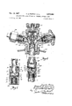
- Fig. 1 is an elevational view, in section, of a valve made in accordance with the present invention
- Fig. 2 is a vertical sectional view of a modified form of the present invention.
- Fig. 3 is an elevational view, in section, of thevalve disclosed in Fig. 2 showing the operative elements in the position they assume under varied conditions ofuse;
- Fig.- 4 is a vertical sectional view of another modified form of the present invention
- Fig. 5 is an elevational view, in section, of'a further modified form of the present invention.
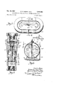
- Figs. 6 and 7 are views showing the vapor agitation induced in the tank by the spray from the embodiment shown in Fig. 4 as taken in section upon lines 7-7 and 6--6 in the respective figures.
- the liquid entering the tank tends to compress the vapor present in the tank with the result that the pressure and temperature of the vapor tend to rise, the pressure more rapidly than the temperature.
- the arc of the spray discharge is approximately degrees so that the vapor is positively circulated to move into the field of spray so that all vapor is brought into intimate contact with the spray.
- the spraying action is accomplished by a diffusion valve which remains closed except when filling operations under pressure are under way. In this way other operations of the valve arrangement are unimpaired.
- Fig. 1 a valve insert unit, generally indicated by referenee numeral 10 which is capable of "being mounted on a filler valve element or coupling 8 to feed liquid into a closed eontainer in the form of a spray, and of evacuating the 1 It s) entire container, should that be necessary, through a liquid eduction tube secured to its lower end.
- the valve is provided with a housing 11 having a central passage 9 including bore 12 terminating in an internal shoulder 13 forming a seat for a sleeve 14 which is slidably mounted within the bore 12 and normally covers a plurality of circumferentially spaced radial ports 15 in the sidewall of the housing.
- the sleeve 14 is provided with an inwardly directed flange 16 to the inner marginal edges of which is secured a filler pipe 17 externally threaded at 18 for reception of the coupling 8.
- a filler pipe 17 externally threaded at 18 for reception of the coupling 8.
- At the upper end of the housing 11 there are internal threads 19 for reception of a correspondingly threaded ring 22, the inner marginal edges of whichare in closely spaced relation to the pipe 17.
- Extending between the ring 22 and the flange 16 is a spring 23 which normally urges the sleeve 14 into contact with the shoulder 13.
- a substantially frusto conical seat 24 joins the bore 12 with a bore 25 in which is concentrically mounted, by means of a spider 26, a check valve assembly 2'7 having a concave retainer disc 28 normally biased into the position shown by a spring 29.
- a liquid outage pipe 7 such as that shown in Fig. 6 may be received for evacuation of the container, as will be apparent.
- the pressure of incoming liquid forces the disc 28 into engagement with the seat 24 and there is formed Within the passage 9,an inlet zone at a pressure substantially greater than the pressure in the zone below the disc 28.
- This pressure forces the entire housing 11 downwardly to uncover the ports 15 and efiEect diffusion of the liquid radially outwardly of the liquid through these ports, Since the vapor pressure within the container will at all times be in excess of the vapor pressure of the fuel, vaporization of the incoming liquid will not occur ifthe'temperature of the incoming liquid is equal to or greater than the temperature of the liquid already in the tank.
- the particles of fuel emitted form a spray pattern Within the container broken up by the heaviness of the vapor present already under pressure.
- the latent heat sometimes referred to herein as the latent heat of condensation, is, of course, absorbed by the incoming liquid and by the liquid already within the container.
- the falling of these fuel particles into the liquid efiects a turbulence which disturbs the surface tension of the liquid and thus the equilibrium at any particular temperature-pressure value.
- valve closure means are, of course, associated with the filler pipe 17 to prevent escape of the contents of the vessel as will be described in conjunction with the remaining figures.
- Fig. 2 a modified form of the present invention in which the spray device constitutes in part a-normally closed back flow check valve in a dual valve arrangement
- the upper valve 10a has a housing 11a provided with a central passage 9a.
- the housing 11a includes a main section 33 having a bore 34 threaded at 35 for reception of a correspondingly threaded upper housing section 36 which has a bore 37 threaded at 38 for reception of a cap 39 which cooperates with a ring 42 to afford sealing of the entire central passage.
- Communicating with the bore 34 is a passage 43 which forms, in conjunction with the bore 34, a shoulder 44 on which rests a gasket 45 received in an annular recess 46 in the lower edge of the upper housing section 36.
- a spider 47 for concentrically mounting a valve stem 48 for the back flow check valve bly to the position shown in the lower dot-and-dash lines 72, described later, having at its upper end a cap 49 normally maintained in spaced relation to the spider 47 by means of a spring 52 to urge the back flow check valve to its closed position.
- integrally formed with the spider 47 is a hollow cylindrical cup 53.
- a spring 54 is mounted in engagement with the outer surface of the cup 53 and norrnaly urges a retainer assembly 55 into engagement with a seat 56, forming a part of the lower extremity of the upper housing section 36.
- the assernbly 55 includes a retainer 57 having a serrated periphery for a purpose hereafter described, and a disc 58 held in position by a retainer washer 59 secured to the retainer 57 by'means of a central screw 62.
- the retainer 57 is formed with a cup 63 which is disposed within the space between the spring 52 and the cup 53.
- a bore 64 internally threaded at 65 for reception of an adapter 66 which forms a part of the housing 11a and which is provided with an elongated bore 67.
- a combination valve seat and spray cage 68 Slidably mounted Within the bore 67 is a combination valve seat and spray cage 68 having a plurality of circumferentially spaced apertures 70 in the sidewall of the adapter 66.
- the check valve disc 72 already referred to is secured by means ofa rivet 73.
- the upper edge of the disc 72 is beveled at 74 for seating on ,upper end of the upper housing 36 as shown in Norway 'U. S. Patent No. 2,361,866, reference to which is hereby made.
- the retainer assembly may be depressed by a suitable tube as shown in the above-mentioned Norway U. S. Patent No. 2,361,866, to the position shown in dot-and-dash lines and into contact with the cap 49 of the stem 48.
- valve 72 In this position the valve 72 is held in position'72e; the slots 69 are out of register with the openings and since there is no pressure within the spray cage to urge it downwardly, the spray cage 68 follows the valve 72 downwardly untilcommunication is fully established with the receiving container. At this time the greater pressure in the lower zone of the valve forces the spray cage to its uppermostposition. The resulting separation of the disc 72 from the edge of the opening 76 forms an annular passage for complete evacuation of the storage container.
- Fig. 5 there is shown in this figure a modified form of the present invention mounted on from the tank in conjunction with a filling valve such as that described in connection with Fig. 2.
- the adapter 66a is internally threaded at the top to be supported on the coupling member 80 and at the bottom the bore 67a is reduced in diameter to provide vertically spaced shoulders 83 and 84.
- a plurality of circumferentially spaced radial openings 70a are provided and the spray cage 68a is provided with slots 69a where they register with the openings 70a when the spray cage rests against the shoulder 83.
- the spray cage 68a is normally held in its raised position by a spring 92, the bottom convolution of which rests upon the shoulder 84.
- the spray cage 68a is cup-shaped and is provided with a plurality of valve port openings 85 in its bottom wall that are closed by a valve disc 86 resting on top of the openings as normally held in this position, preferably by a compression spring 87 engaging the head 89 of a pin 90 secured to the valve disc as shown.
- a compression spring is preferred but it has been found that gravity closure of the valve disc is adequate when the valve is mounted vertically.
- the disc 86 is normally in the closed position shown, i. 6., in engagement with the bottom of the spray cage 68a.
- the resulting pressure forces the spray cage 68a downwardly until the slots 69a are in register with the openings 70a.
- This downward movement of the spray cage compresses the spring 92, and, of course, the spring returns the cage to the position shown when the feed pressure is removed.
- this adapter is employed for evacuation of a storage container or vessel as when the valves 55 and 72 are held open the relief of pressure above the valve disc 86 causes the disc 86 to rise under the pressure below the cage, thus compressing the spring 87, if present.
- the valves 55 and 72 are closed and the disc 86 again closes the ports 85.
- the composite valve shown in this figure comprises a body 110 having three bosses 91, 92 and 93 attached to a tank c by a flange 10b as shown in Fig. 5.
- a double filler valve arrangement 105 is provided within the threaded opening 94 where they are in communication with the central passage 106 as supported in part on an integral spider 95 at the bottom of the passage 106.
- the structure and operation of the valve arrangement is more fully described in the Sundstrom U. S. Patent No. 2,713,874, reference to which is hereby made.
- valves 96 and 97 are normally closed vertically spaced valves supported in alignment to open inwardly for the admission of liquid under pressure and are so arranged that they can be held open for the evacuation of liquid if desired.
- the boss 93 receives a normal shut-off valve assembly 107 of the diaphragm sealed type which closes at seat 108 to control the flow of liquid to household appliances from the central passage 106 as safeguarded by the orifice restriction at 109 and as connected to a service conduit at the opening shown in dotted lines 110a.
- the lower end of the body portion 110 is provided with internal threads to receive an extension nipple 18a and a pipe adapter 18b for supporting the spray device at a predetermined level in the tank 100. See Sundstrom U. S. Patent No. 2,341,579, wherelength might be important. e
- the remaining boss 92 has a passage 111. in communication with the central passage 106 and is threaded at 112 to receive a valve fitting (not shown) for dispensing liquid to farm equipment such as propane powered tractors.
- the element 113 shown is a plug for closing this passage until the transfer hose fitting is installed.
- a The spray device in this embodiment is similar in many respects to thatshown in Fig. 5, same having a body 6612 with shoulders 83a and 84a therein, a spray cage 8615 having openings at the bottom thereof closed by a valve disc 86 as already described.
- the body 66b has a narrow horizontal slot 114 extending approximately 180 degrees around the body 6612 and the sidewall 115 of the cage 68b is of such length that the slot 114 is exposed above the upper edge of thesidewall when the cage 68b rests against the shoulder 83a.
- the spray cage 68b is forced downwardly byincoming liquid, the liquid flows over the upper edge thereof wherever the slot 114 is located.
- a service line (Fig. 6) which includes a first stage pressure reducer that provides for vaporization of the liquid fuel educted through the ports 85 and past the disc 86, and a last stage pressure regulator for dispensing gas at eleven inches of water column at the appliance.
- a service line (Fig. 6) which includes a first stage pressure reducer that provides for vaporization of the liquid fuel educted through the ports 85 and past the disc 86, and a last stage pressure regulator for dispensing gas at eleven inches of water column at the appliance.
- liquid fuel can be dispensed to a tractor fuel tank through the boss 92 with suitable valving and how liquid fuel in the tank can be evacuated if the tank is to be moved as described in the above-mentioned Norway patent.
- Figs. 6 and 7 in connection with the embodiment shown in Fig: 4.
- the tank 10c is shown to be an elongated one supported horizontally on blocks 119 with the liquid level of the tank shown at 120a and a pressure filling hose 121 attached to the threads 77.
- the replenishing liquid is being taken from a supply tank 128 and forced by pump 129 into the tank 10c through the slot 114 as fanned out by the shape of the slot.
- the liquid spray Since the liquid spray is opposed in its movement by the heavy vapor present in the tank under high pressure, it is broken up into fine droplets that move through the vapor with a trajectory greatly accelerated above that experienced with liquids discharged into the atmosphere. Because of this quick trajectory and the inertia of the heavy vapor, much of the vapor space in a horizontally disposed tank will not be reached by the droplets.
- the propane vapor pressure in the storage tank can be presumed to be p. s. i. (pound per square inch) gauge (10.54 kg./cm. at a temperature of approximately 90 F. (32 C.).
- p. s. i. compound per square inch gauge
- a usual empty condition of a 500 gallon storage tank about 25% full can also be considered for purposes of discussion and such is to be filled to approximately 85%.
- pumps employed in the art vary, a positive displacement pump expected to deliver 50 gallons per minute under a pressure differential of 75 p. s. i. (5.27 kg./cm. 'can be used. With approximately 290 gallons to be pumped, the desired pumping time would be approximately six minutes.
- the latent heat content of the thirty-five gallons of vapor is approximately 770 B. t. u. and the heat content of thirty-four gallons of liquid would be approximately 405 B. t. u. per gallon.
- the 770 B. t. u. could be absorbed by thirty-four gallons of liquid which means 12 B. t. u. per gallon, which would raise the temperature of the liquid to approximately 120 F. (49 C.) if there is no loss from the system.
- the new equilibrium would be a vapor pressure of 225 p. s. i. (15.82 kg./cm. This is within 25 p. s. i. (1.76 kg./cm. of the pop-ofi? pressure of the safety valve of the storage tank system.
- liquid already in the tank can be utilized to keep the temperature down some, and with the latent heat of 375 gallons of vapor distributed in 425 gallons of liquid, the ultimate vapor pressure rise would be only to 185 p. s. i. (13 kg./cm.
- the temperature of the incoming fuel is lowered because of vaporization taking place in the supply tank and this lowering is inversely related to the rise of temperature expected in the storage tank. This is a further factor in absorbing latent heat from the compressed vapor because the cooler the incoming liquid is the more capacity it has to absorb heat from the vapor space without running the resulting temperature of the liquid in the storage tank as high as otherwise might be the case, as already indicated.
- the spray is confined to an angle of 180 degrees. This not only increases the drive of the spray to penetrate the vapor, but causes a positive circulation of vapor in the tank in the directions of the arrows 130 in Figs. 6 and 7.
- the spray hitting half of the vapor in the space with a directional effect causes the vapor to move and the vapor which is not in the spray area is moved into the spray progressively so that all the vapor passes time and again through the spray area where thermal units are absorbed by the liquid spray particles and some vapor is condensed. All the vapor thus passes through the spray area and with gradual lowering of temperature of the incoming liquid, the temperature of vapor is controlled uniformly throughout its body and kept quite low.
- a combination valve for use in filling a storage vessel with liquefied petroleum gas or for evacuating gas from the vessel comprising a housing, said housing having a central passage, defining an inlet opening, a filler pipe for receiving replenishing liquid under pressure con nected to said opening arranged Within said'passage, a plurality of circumferentially spaced apertures in said housing, a sleeve of greater diameter than said pipe disposed in abutting relation to the inside surface of said passage, said sleeve normally covering said openings and being joined to said pipe, a normally open check valve carried by said housing positioned in said central passage closing in the direction of flow of replenishing liquid entering said passage, a spring arranged in surrounding relation to said pipe and operative to maintain the covering relation of said sleeve with respect to said openings, whereby upon the introduction of the liquefied gas under pressure said valve is closed and the housing is urged into a position in which the openings are uncovered to afford spraying of the liquefied gas throughouta relatively
- a combination valve for use in filling a storage vessel with liquefied gas or for evacuating gas from the vessel comprising a relatively movable housing, a central passage formed in said housing, said passage including a bore formed in one end and communicating with a second bore extending from the other end of said housing and forming an internal shoulder, a stationary filler pipe disposed withinsaid first bore, said housing being formed with a plurality of circumferentially spaced ports adjacent said shoulder, a sleeve positioned within said first bore and normally covering said ports, said sleeve having'an 'inwardl'y' directed flange secured to said filler pipe, a spider disposed transversely across said passage in close proximate relation to said shoulder, a valve mounted 'on said spider and operative upon actuation to move axially of said passage, said shoulder being formed with an annular seat for said valve, the other end of said first bore having internal threads for reception of a sealing ring mounted in surrounding relation to said filler pipe, a
- a combination valve for use in filling a storage vessel with liquefied gas or for evacuating gas from the vessel comprising a housing, a central passage formed in said housing, said passage including a bore formed in one end and communicating with a second bore extending from the other end of said housing and forming an internal shoulder, a filler pipe disposed within said first bore, said housing being formed with a plurality of circumferentially spaced ports adjacent said shoulder, a sleeve positioned within said first bore and normally covering said normallyclosi-ng said port.
- said sleeve having an inwardly directed flange secured to said filler pipe, a normally open valve mounted centrally of said passage, said shoulder being formed with an annular seat for said valve, the other end of said first bore having internal threads for reception of a sealing ring mounted in surrounding relation to said filler pipe, a compression spring arranged about said filler pipe and extending between said flange and said ring whereby upon the introduction of liquefied gas under pressure said valve is closed and the housing is movedaxially of the filler pipe so that the ports are uncovered to effect spraying of the liquid over a relatively wide area in said vessel and when ,a low pressure area is created in said first bore, saidvalve is unseated to afford evaq lation of the contents of the vessel.
- a tank for storing liquefied gas under pressure a filler valve mounted at an opening in the tank, and a device for spray filling and liquid eduction of said tank, said device comprising housing means communicating with the filler valve, a central passage in said housing means, one end of said passage forming an inlet connected to said filler valve for the introduction of replenishing liquefied-gas under pressure into said tank and the other end forming an opening spaced from said inlet, a dip pipe communicating with said opening and extending to a point adjacent the bottom of the tank to place said passage in communication with said tank, said housing means having a horizontally directed radial port formed in the side thereof intermediate said inlet and said opening, means including a member slidably mounted insaid housing means for relative axial movement with respect thereto to open and close said radial port, an upper stop means and a lower stop means on said housing means for limiting said relative movement between a position closing said radial port and a position opening saidradial port, means for
- a tank for storing liquefied gas under pressure and flow control means mounted at an opening in the tank for spray filling and withdrawing liquefied gas comprising a filler valve, aflow directing device and a dip tube extending to a point adjacent the bottom of the tank, said device including a,housing'inter-connecting the filler valve and dip tube and having a central passage therein in communication at its top: withsaid filler valve and atits bottom with the dip tube and having a laterally directed spray, port inthe side thereof intermediate its top and bottom in communication with the tank near the top .thereof, means including a member mounted in said housing for relative axial movement with respect thereto, an .upper stop means and a lower stop means for limiting said relative movement between a position closing said port and] a position opening saidport, means for placing said dip tube in opencommunication with said filler valve through said passage including a valve element and a valve seat element in said housing opening in the direction of flow of liquid from the dip tube to the filler
- a valve assembly for spray filling the storage tank withlique'fied gas and for withdrawing liquefied gas from the tank comprising a plurality of tubular members slidably mounted one within the other for relative axial movement therebetween and defining a flow passage axially therethrough, one of the members defining an inside Wall upon which the other one slides, one end of the passage defining an inlet opening for fluid entering the tank, the other end below the telescoping overlap defining an outlet opening, a dip tube connected to said outlet opening and extending to a point adjacent to the bottom of the tank for educting fluid from the tank, the outside one of said members having a port therein disposed inla horizontal plane over a portion of the circumference of said outside member intermediate said openings, an upper stop means and a lower stop means on said outside member upon opposite sides of said port for limiting movement of the inner one of said members from a normal relative position in which said port is covered by said inner member to another relative position
- a tank for storing liquefied gas under pressure and having a valve receiving opening in a wall thereof, and a dip tube extending to a point adjacent the bottom thereof, a combination spray filler and flow control valve assembly mounted in said opening and connected to said clip tube for use in filling the storage tank from a point above the liquid level thereof with liquefied gas and for withdrawing liquefied gas from a point near the bottom of the tank comprising an elongated housing, a central passage in said housing, one end of said housing forming an inlet for said passage to receive replenishing liquefied gas introduced under pressure and the other end of said housing forming an outlet to said passage from said tank through said dip tube, a plurality of circumferentially spaced radial ports adjacent said inlet formed in said housing near the top of the tank and in communication with said passage, means including an inflow check valve disposed adjacent the outlet end of said passage for closing said outlet in response to pressure in said passage, means slidably
- a spray filler and flow control valve assembly mounted at an opening in said tank comprising a housing carrying a dip tube extending to a point adjacent the bottom of the tank, a central passage formed in said housing, said housing being formed with a plurality of circumferentially spaced ports, means mounted within said passage for normally closing said ports, a flow check valve mounted in said passage and dividing said passage into two zones, said valve closing when fluid in one zone is at a higher pressure than in the other zone, said one of said zones being in communication with one end of said housing to receive replenishing fluid and the other oi "said zones being in communication at the other end of sa'id'housing with a point near the bottom of the tank through said dip tube to receive liquid educted from the tank, said ports opening into said one of said zones near the top of the vessel, means including a slidable element disposed within said housing for relative movement between said housing and said first means to effect opening of said ports upon the clos
- said spray cage having an opening registering with said port when liquid under pressure is introduced into said passage through said inlet, said cage having a concentric stem, a spring normally urging said stem to carry said opening of said cage out of register with said port to close the port, a check valve carried by'said cage at the lower end of said stem for cooperation with a seat formed in the bottom Wall of said cage, whereby upon the lowering of the pressure in said inlet zone and manual displacement of said stern and said check valve the cage is separated from said check valve and a path is provided therethrough for educting liquefied gas from the tank.
- a valve assembly for mounting in a fluid passage and comprising a housing having a flow passage extending lengthwise therethrough and defining an inside wall for the body, means on one end of said housing defining an inlet opening for said passage including a filler valve, the other end of the passage defining a withdrawal opening formed in the housing, the housing having a plurality of outlet ports formed therein arranged substantially in a plane passing through the body intermediate said openings, sleeve means slidable in the passage and being of suflicient size to cover said outlet ports, means for limiting movement of the sleeve means in the direc tion toward said withdrawal opening to close said outlet ports, said sleeve means being movable in the direction opposite to said first direction to a position where the ports will be uncovered, and means for yieldably holding the sleeve means in said position closing said ports, and check valve means in the housing including a valve seat between said withdrawal opening and said ports and a valve element cooperating therewith to open said seat by movement in the direciton of
- a valve assembly for mounting in a fluid passage and comprising a filler valve and a flow control device, said device including a housing having a chamber in communication with the filler valve at one end and defining an inlet opening at the other end of said chamber,
- said housing having a port through a side wall of the chamber, a member slidably mounted in said chamber to move from a position covering said port to a position uncovering said port, means resiliently holding said member in said relative port covering position including a stop element between said filler valve and said port, and valve means between said filler valve and said inlet opening including a valve element and a valve seat element in said housing movable relative to each other to a closed posiing, said housing having a spray outlet port through the side of the housing intermediate said inlet and withdrawal opening, a sleeve axially slidable in said passage and being of sutficient axial length to cover said outlet port, check valve means including a valve seat element on said sleeve facing said withdrawal opening and a valve element engaging said valve seat element and movable in the direction of said inlet opening to close against said seat, spring means for urging said valve element to said closed position to urge said sleeve to a position closing said outlet port, filler valve means in said inlet opening, and
- a valve assembly for mounting in a fluid passage comprising a main body and a tubular housing interconnected by an externally threaded coupling to define an elongated flow passage, a spray outlet port through the side of said tubular housing below said coupling, the end of the passage in said body defining an inlet, a normally closed back flow check valve in said inlet opening towards said passage, the end of the passage in said tubular housing defining a withdrawal opening, a sleeve axially slidable in said passage for movement between positions opening and closing said outlet port, check valve means remote from the end of the sleeve adjacent said inlet opening, shoulder means on the coupling defining a valve seat above said outlet port and determining the position of the sleeve when closing said outlet port, a valve member closing against said valve seat and including a valve stem displaced by said back flow check valve when opened,
- valve element moving to within the confines of said sleeve when said valve stem is so displaced, and means for urging said sleeve into engagement with said coupling to close said outlet port.
- said slidable member comprises a spray cage having a circumferentially disposed slot registering with said port 'by a coupling member terminating at the bottom in a valve seat member for said filler valve and a shoulder constituting said stop element.
Description
Nov 19, 1957 RE. POETHIG ET AL 2,313,402
APPARATUS FOR LIQUID FILLING OF PRESSURE STORAGE TANKS Filed Aug. 10, 1955 3 Sheets-Sheet 1 //0a, 94. w /08 A HI! I 05 i. wk
Nov. 19, 1957 R. E. POETHIG ET AL APPARATUS FOR LIQUID FILLING OF PRESSURE STORAGE TANKS 3 Sheets-Sheet 2 Filed Aug. 10, 1955 A w u a 7 a aw J8 W NIH IIIJIII s fifi i z? W rzzeg 1957 R. E. POETHIG ETAL 2,313,402
APPARATUS FOR LIQUID FILLING 0F PRESSURE STORAGE TANKS Filed Aug. 10, 1955 3 Sheets-Sheet 3 rzz/elziirs ,e Z/q; damsFEaZZazyZorz ,eoaeyiggo I i" 2,;
United States Patent Ofiice 2,813,402 Patented Nov. 1 9, 1 957 APPARATUS FOR LIQUID FILLING F PRESSURE STORAGE TANKS Robert E. Poethig, Glenview, and. Evans R. hillington,
Chicago, Ill., assiguors to The Bastian-blessing Company, Chicago, 111., a corporation of Illinois Application August 10, 1955, Serial No. 527,522
17 Claims. (Cl. 62-1) This invention relates to liquefied gas systems and valve controls and more particularly to a method and combination of valves for handling liquefied gas which are primarily directed to improvements in the filling and withdrawal of liquefied gas from a pressure storage tank.
When liquefied gas storage tanks are being replenished conventionally under high pump pressures, the vapor present in the tank is rapidly compressed. Its temperature also goesup and unless sensible heat is removed from the vapor, the vapor will not condense sutficiently tokeep the pressure down. Although there is some heat absorption and precipitation on the inside metal surfaces of the tank and at the surface of the body of liquid already present in thetank, stratification quickly occurs at these surfaces because of, the heavy inertness of the vapor. and liquid and prevents any further substantial heat transferfrom the vapor. Thus the vapor present in the tank iscompressed far more rapidly than the vapor can liquefy and the increasing pressure decreases the ciliciency of the pump and lengthens the time of filling operations. r
Attempts have been made in the past to prevent pressure rise in the storage tank by providing a separate line for vapor return to the tank truck to balance vapor pressures. This arrangement has proved unsatisfactory because of the inconvenience of coupling two separate lines between the truck and the tank, and, furthermore, the amount of fuel actually delivered was difiicult to compute, because of the fact that there was no quick and effective way to determine just how much fuel was returned to the tank truck. Bleeding the vapor to atmosphere is dangerous and refrigeration equipment is expensive and cumbersome.
With the foregoing difficulties confronting the industry, a principal object of the invention is to provide a method and valve means by which a tank may be filled to capacity at a continuously high rate with only the connection of the filler hose to the storage tank.
A further object of the invention is to prevent any substantial increase in vapor pressure within the tank during filling operations so that replenishing liquid may be introduced at full speed throughout the filling operations.
The invention is also characterized by a breaking up,
of the incoming liquid into a spray of minute droplets so directed that the vapor in the tank is circulated into the path of spray and into intimate heat exchange contact with the droplets for quick precipitation.
Another object-of the invention is to provide assured cooling of the vapor in the tank by agitated absorption of heat therefrom to liquefy, as a continuing process, largeamounts of the vaporpresent in the tank that otherwise would cause an increase in pressure. This agitation is accomplished by splashnig the liquid already present in the tank, hard spraying the incoming liquid through the vapor space, and :by agitated circulation of the vapor in the vapor space. i o
Another object of the invention is to provide a valve wherein the inrus'hingliquid is ejected in a wide spray 2 pattern into the tank at the top of the vapor space to break up stratification and surface tensions of the liquid in the tank and thereby enhance absorption of latent heat from the vapor at the temperature and pressure critical for its precipitation.
A further object of the invention is to provide a method by means of which liquefied gas may be fed rapidly at a sustained high rate into a storage vessel, the high rate of filling serving to assist itself. in proportion to its "at? f fi r An additional object of the invention is to provide a composite valve means by which fuel may be fedrapidly into a tank in a mannerthat the development of excessive back pressures are prevented, without interfering with the normal operation and functions of the liquefied gas storing and dispensing system.
Other and further objects, advantages and features of the. present invention will be apparent to those skilled in the art from the following description, taken in conjunction with the accompanying drawings in which similar referencecharacters relate to similar parts, and in which: Fig. 1 is an elevational view, in section, of a valve made in accordance with the present invention;
Fig. 2 is a vertical sectional view of a modified form of the present invention; r
Fig. 3 is an elevational view, in section, of thevalve disclosed in Fig. 2 showing the operative elements in the position they assume under varied conditions ofuse;
Fig.- 4 is a vertical sectional view of another modified form of the present invention; i i 3 Fig. 5 is an elevational view, in section, of'a further modified form of the present invention; and. i
Figs. 6 and 7 are views showing the vapor agitation induced in the tank by the spray from the embodiment shown in Fig. 4 as taken in section upon lines 7-7 and 6--6 in the respective figures. i
In the present invention where replenishing liquid is pumped into a storage tank under forced conditions, the liquid is sprayed against a heavy vapor as it exists-under as much as pounds per square inch gauge. The impact upon this body of vapor breaks up the spray in fine droplets which pass into the vapor space in the tank. As the liquid is broken up into fine streams and droplets it not. only isdriven into intimate heat exchange with the vapor in the tank being filled, but forces the vapor to moveand also splashes into the vapor space the liquid already present in the tank. i
The liquid entering the tank tends to compress the vapor present in the tank with the result that the pressure and temperature of the vapor tend to rise, the pressure more rapidly than the temperature. With theincrease of pressure the normal vapor pressure equilibrium in the tank is disturbed and a condensation of vapor begins which is greatly accelerated by the incoming droplets seeding precipitation, and with condensation occurring, thermal units are surrendered as latent heat from .the vapor to the liquid in the tank with little increase in temperature. In the preferred embodiment, the arc of the spray discharge is approximately degrees so that the vapor is positively circulated to move into the field of spray so that all vapor is brought into intimate contact with the spray.
In performing the method of the present invention the spraying action is accomplished by a diffusion valve which remains closed except when filling operations under pressure are under way. In this way other operations of the valve arrangement are unimpaired.
Referring now to Fig. 1, there is shown in this. Fig. 1 a valve insert unit, generally indicated by referenee numeral 10 which is capable of "being mounted on a filler valve element or coupling 8 to feed liquid into a closed eontainer in the form of a spray, and of evacuating the 1 It s) entire container, should that be necessary, through a liquid eduction tube secured to its lower end. The valve is provided with a housing 11 having a central passage 9 including bore 12 terminating in an internal shoulder 13 forming a seat for a sleeve 14 which is slidably mounted within the bore 12 and normally covers a plurality of circumferentially spaced radial ports 15 in the sidewall of the housing. The sleeve 14 is provided with an inwardly directed flange 16 to the inner marginal edges of which is secured a filler pipe 17 externally threaded at 18 for reception of the coupling 8. At the upper end of the housing 11 there are internal threads 19 for reception of a correspondingly threaded ring 22, the inner marginal edges of whichare in closely spaced relation to the pipe 17. Extending between the ring 22 and the flange 16 is a spring 23 which normally urges the sleeve 14 into contact with the shoulder 13. A substantially frusto conical seat 24 joins the bore 12 with a bore 25 in which is concentrically mounted, by means of a spider 26, a check valve assembly 2'7 having a concave retainer disc 28 normally biased into the position shown by a spring 29. At the lower end of the housing 11 and communicating with the bore 25 is an internally threaded bore 32 in which aliquid outage pipe 7 such as that shown in Fig. 6 may be received for evacuation of the container, as will be apparent.
In operation, the pressure of incoming liquid forces the disc 28 into engagement with the seat 24 and there is formed Within the passage 9,an inlet zone at a pressure substantially greater than the pressure in the zone below the disc 28. This pressure forces the entire housing 11 downwardly to uncover the ports 15 and efiEect diffusion of the liquid radially outwardly of the liquid through these ports, Since the vapor pressure within the container will at all times be in excess of the vapor pressure of the fuel, vaporization of the incoming liquid will not occur ifthe'temperature of the incoming liquid is equal to or greater than the temperature of the liquid already in the tank. On the other hand, the particles of fuel emitted form a spray pattern Within the container broken up by the heaviness of the vapor present already under pressure. These particles or droplets collide with the saturated vapor particles and provide a suflicient exchange of heat to effect precipitation of the vapor particles. The latent heat, sometimes referred to herein as the latent heat of condensation, is, of course, absorbed by the incoming liquid and by the liquid already within the container. In addition, the falling of these fuel particles into the liquid efiects a turbulence which disturbs the surface tension of the liquid and thus the equilibrium at any particular temperature-pressure value.
When the feed pressure is removed the housing 11 returns to the position shown and the ports 15 are again covered. The valve disc is again biased to the position shown by the spring 23 and the valve is in position for evacuation. Suitable valve closure means are, of course, associated with the filler pipe 17 to prevent escape of the contents of the vessel as will be described in conjunction with the remaining figures.
In Fig. 2 is shown a modified form of the present invention in which the spray device constitutes in part a-normally closed back flow check valve in a dual valve arrangement where the upper valve 10a has a housing 11a provided with a central passage 9a. The housing 11a includes a main section 33 having a bore 34 threaded at 35 for reception of a correspondingly threaded upper housing section 36 which has a bore 37 threaded at 38 for reception of a cap 39 which cooperates with a ring 42 to afford sealing of the entire central passage. Communicating with the bore 34 is a passage 43 which forms, in conjunction with the bore 34, a shoulder 44 on which rests a gasket 45 received in an annular recess 46 in the lower edge of the upper housing section 36. Within the passage 43 is formed a spider 47 for concentrically mounting a valve stem 48 for the back flow check valve bly to the position shown in the lower dot-and-dash lines 72, described later, having at its upper end a cap 49 normally maintained in spaced relation to the spider 47 by means of a spring 52 to urge the back flow check valve to its closed position. integrally formed with the spider 47 is a hollow cylindrical cup 53. A spring 54 is mounted in engagement with the outer surface of the cup 53 and norrnaly urges a retainer assembly 55 into engagement with a seat 56, forming a part of the lower extremity of the upper housing section 36. The assernbly 55 includes a retainer 57 having a serrated periphery for a purpose hereafter described, and a disc 58 held in position by a retainer washer 59 secured to the retainer 57 by'means of a central screw 62. The retainer 57 is formed with a cup 63 which is disposed within the space between the spring 52 and the cup 53.
Communicating with the passage 43 is a bore 64 internally threaded at 65 for reception of an adapter 66 which forms a part of the housing 11a and which is provided with an elongated bore 67. Slidably mounted Within the bore 67 is a combination valve seat and spray cage 68 having a plurality of circumferentially spaced apertures 70 in the sidewall of the adapter 66. At the lower end'of the stem 48 the check valve disc 72 already referred to is secured by means ofa rivet 73. The upper edge of the disc 72 is beveled at 74 for seating on ,upper end of the upper housing 36 as shown in Norway 'U. S. Patent No. 2,361,866, reference to which is hereby made. The incoming liquid acts upon the upper surface of the retainer assembly 55 and forces the assem- 55d in this figure, thus compressing the spring 54. Downward movement of the stem 48, along with the spray cage 68, is afiorded by the flow of liquid about the serrated periphery of the retainer 57, and through the spider 47. As the spray cage 68 moves downwardly in' response to the liquid pressure (see 72d), the slots 69 are brought to the position shown in the lower dot- :and-dash lines 69d in which position they register with an unobstructed path is provided through the valve for the openings 70 in the sidewall of the adapter 66. Thus flowof the liquid. On emission fromthe openings 70 v as broken up by the resistance of the body of compressed vapor, the fuel is dispersed outwardly in a shower of tiny particles-which are at a lower temperature than the vapor being compressed in the storage container. The result is the absorption of latent heat from the vapor within the storage tank and consequent precipitation of the saturated vapor. v p i When evacuation of thestorage tank is desired, the retainer assemblymay be depressed by a suitable tube as shown in the above-mentioned Norway U. S. Patent No. 2,361,866, to the position shown in dot-and-dash lines and into contact with the cap 49 of the stem 48. In this position the valve 72 is held in position'72e; the slots 69 are out of register with the openings and since there is no pressure within the spray cage to urge it downwardly, the spray cage 68 follows the valve 72 downwardly untilcommunication is fully established with the receiving container. At this time the greater pressure in the lower zone of the valve forces the spray cage to its uppermostposition. The resulting separation of the disc 72 from the edge of the opening 76 forms an annular passage for complete evacuation of the storage container.
Referring now to Fig. 5, there is shown in this figure a modified form of the present invention mounted on from the tank in conjunction with a filling valve such as that described in connection with Fig. 2. The
already described to close against the seat 76a.
In this embodiment the adapter 66a is internally threaded at the top to be supported on the coupling member 80 and at the bottom the bore 67a is reduced in diameter to provide vertically spaced shoulders 83 and 84. A plurality of circumferentially spaced radial openings 70a are provided and the spray cage 68a is provided with slots 69a where they register with the openings 70a when the spray cage rests against the shoulder 83. As shown, the spray cage 68a is normally held in its raised position by a spring 92, the bottom convolution of which rests upon the shoulder 84. Moreover, the spray cage 68a is cup-shaped and is provided with a plurality of valve port openings 85 in its bottom wall that are closed by a valve disc 86 resting on top of the openings as normally held in this position, preferably by a compression spring 87 engaging the head 89 of a pin 90 secured to the valve disc as shown. The use of a compression spring is preferred but it has been found that gravity closure of the valve disc is adequate when the valve is mounted vertically.
In the operation of the valve adapter of Fig. 5, the disc 86 is normally in the closed position shown, i. 6., in engagement with the bottom of the spray cage 68a. When liquid under pressure is introduced past the filler valve the resulting pressure forces the spray cage 68a downwardly until the slots 69a are in register with the openings 70a. This downward movement of the spray cage compresses the spring 92, and, of course, the spring returns the cage to the position shown when the feed pressure is removed. When this adapter is employed for evacuation of a storage container or vessel as when the valves 55 and 72 are held open the relief of pressure above the valve disc 86 causes the disc 86 to rise under the pressure below the cage, thus compressing the spring 87, if present. When the desired contents of the storage vessel have been evacuated the valves 55 and 72 are closed and the disc 86 again closes the ports 85.
Referring now to Fig. 4, the composite valve shown in this figure comprises a body 110 having three bosses 91, 92 and 93 attached to a tank c by a flange 10b as shown in Fig. 5. Instead of the valve retainer assembly 55, however, a double filler valve arrangement 105 is provided within the threaded opening 94 where they are in communication with the central passage 106 as supported in part on an integral spider 95 at the bottom of the passage 106. The structure and operation of the valve arrangement is more fully described in the Sundstrom U. S. Patent No. 2,713,874, reference to which is hereby made.
It is sufiicient here to note that the two valves 96 and 97 are normally closed vertically spaced valves supported in alignment to open inwardly for the admission of liquid under pressure and are so arranged that they can be held open for the evacuation of liquid if desired.
The boss 93 receives a normal shut-off valve assembly 107 of the diaphragm sealed type which closes at seat 108 to control the flow of liquid to household appliances from the central passage 106 as safeguarded by the orifice restriction at 109 and as connected to a service conduit at the opening shown in dotted lines 110a.
The lower end of the body portion 110 is provided with internal threads to receive an extension nipple 18a and a pipe adapter 18b for supporting the spray device at a predetermined level in the tank 100. See Sundstrom U. S. Patent No. 2,341,579, wherelength might be important. e
The remaining boss 92 has a passage 111. in communication with the central passage 106 and is threaded at 112 to receive a valve fitting (not shown) for dispensing liquid to farm equipment such as propane powered tractors. The element 113 shown is a plug for closing this passage until the transfer hose fitting is installed.
A The spray device in this embodiment is similar in many respects to thatshown in Fig. 5, same having a body 6612 with shoulders 83a and 84a therein, a spray cage 8615 having openings at the bottom thereof closed by a valve disc 86 as already described. However, in this embodiment the body 66b has a narrow horizontal slot 114 extending approximately 180 degrees around the body 6612 and the sidewall 115 of the cage 68b is of such length that the slot 114 is exposed above the upper edge of thesidewall when the cage 68b rests against the shoulder 83a. Thus when the spray cage 68b is forced downwardly byincoming liquid, the liquid flows over the upper edge thereof wherever the slot 114 is located.
The operation of dispensing liquid for household use through the shut-olf valve 107 in Fig. 5 will be understood by those skilled in the art by two or more stages of pressure reduction (not shown) in a service line (Fig. 6) which includes a first stage pressure reducer that provides for vaporization of the liquid fuel educted through the ports 85 and past the disc 86, and a last stage pressure regulator for dispensing gas at eleven inches of water column at the appliance. Moreover, it will be appreciated how liquid fuel can be dispensed to a tractor fuel tank through the boss 92 with suitable valving and how liquid fuel in the tank can be evacuated if the tank is to be moved as described in the above-mentioned Norway patent.
However, in connection with the filling of the tank with liquid under forced pressure and a further understanding of the operation of the invention, reference is made to Figs. 6 and 7 in connection with the embodiment shown in Fig: 4. The tank 10c is shown to be an elongated one supported horizontally on blocks 119 with the liquid level of the tank shown at 120a and a pressure filling hose 121 attached to the threads 77. The replenishing liquid is being taken from a supply tank 128 and forced by pump 129 into the tank 10c through the slot 114 as fanned out by the shape of the slot.
Since the liquid spray is opposed in its movement by the heavy vapor present in the tank under high pressure, it is broken up into fine droplets that move through the vapor with a trajectory greatly accelerated above that experienced with liquids discharged into the atmosphere. Because of this quick trajectory and the inertia of the heavy vapor, much of the vapor space in a horizontally disposed tank will not be reached by the droplets.
This is significant because, as the liquid is forced into the tank, it physically displaces vapor volume and compresses the vapor present in the space. With this compression, the pressure tends to rise in the tank and the temperature also. Liquid temperatures in the supply and storage tanks being the same, the incoming liquid cannot vaporize against the resultant pressure in the storage tank that becomes higher than its vapor pressure, nor can the liquid at the bottom of the tank vaporize for the same reason.- The increase of pressure unbalances the vapor pressure equilibrium of the fuel in the storage tank and condensation is to be expected. However, for condensation to take place, latent heat should be absorbed from the vapor.
More specifically, assuming a set of conditions for purposes of example and explanation, the propane vapor pressure in the storage tank can be presumed to be p. s. i. (pound per square inch) gauge (10.54 kg./cm. at a temperature of approximately 90 F. (32 C.). A usual empty condition of a 500 gallon storage tank about 25% full can also be considered for purposes of discussion and such is to be filled to approximately 85%. Although pumps employed in the art vary, a positive displacement pump expected to deliver 50 gallons per minute under a pressure differential of 75 p. s. i. (5.27 kg./cm. 'can be used. With approximately 290 gallons to be pumped, the desired pumping time would be approximately six minutes.
In order to maintain the original pressure differential for pumping efiiciencypapproximately thirty-five gallons of vapor must be condensed to receive thirty-four gallons of replenishing liquid with the end result that the liquid content of the tank has been increased thirty-five gallons, it being understood that approximately one unit of liquid is derived from the condensation of thirty-five units of vapor. To maintain substantially the same pressure differential, theoretically the vapor has to be condensed as fast as it is displaced by liquid.
The latent heat content of the thirty-five gallons of vapor (one gallon liquid) is approximately 770 B. t. u. and the heat content of thirty-four gallons of liquid would be approximately 405 B. t. u. per gallon. In absorbing 770 B. t. u. of latent heat from the vapor (thirty-five gallons) to condense it, the 770 B. t. u. could be absorbed by thirty-four gallons of liquid which means 12 B. t. u. per gallon, which would raise the temperature of the liquid to approximately 120 F. (49 C.) if there is no loss from the system. Thus the new equilibrium would be a vapor pressure of 225 p. s. i. (15.82 kg./cm. This is within 25 p. s. i. (1.76 kg./cm. of the pop-ofi? pressure of the safety valve of the storage tank system.
However, liquid already in the tank can be utilized to keep the temperature down some, and with the latent heat of 375 gallons of vapor distributed in 425 gallons of liquid, the ultimate vapor pressure rise would be only to 185 p. s. i. (13 kg./cm. Furthermore, the temperature of the incoming fuel is lowered because of vaporization taking place in the supply tank and this lowering is inversely related to the rise of temperature expected in the storage tank. This is a further factor in absorbing latent heat from the compressed vapor because the cooler the incoming liquid is the more capacity it has to absorb heat from the vapor space without running the resulting temperature of the liquid in the storage tank as high as otherwise might be the case, as already indicated.
In order for the system to work with the greatest efiiciency, however, it is necessary that the incoming liquid contact all of the vapor as thoroughly as possible. However, with the heavy compressed condition (high density) of the vapor that is present, the spray of the liquid will not penetrate as far as would be expected under atmospheric pressure (lesser density), and with the spray pattern spread over an angle of 360 degrees, i. e., a circular spray pattern, stagnation of vapor exists in the tank where the spray does not and cannot reach the vapor. Temperatures in these areas rise very substantially due to vapor compression, both the temperature and pressure supplementing each other for very high temperatures and high pressures.
In the embodiment shown in Figs. 4, 6 and 7, the spray is confined to an angle of 180 degrees. This not only increases the drive of the spray to penetrate the vapor, but causes a positive circulation of vapor in the tank in the directions of the arrows 130 in Figs. 6 and 7. The spray hitting half of the vapor in the space with a directional effect causes the vapor to move and the vapor which is not in the spray area is moved into the spray progressively so that all the vapor passes time and again through the spray area where thermal units are absorbed by the liquid spray particles and some vapor is condensed. All the vapor thus passes through the spray area and with gradual lowering of temperature of the incoming liquid, the temperature of vapor is controlled uniformly throughout its body and kept quite low.
Thus it is possible to fill a storage tank with as little 8 pressure rise as twenty pounds with a substantially coristant quantity of fifty gallons per unit of time in the time suggested, it being appreciated that some loss of thermal units from the storage tank to atmosphere is of assistance in this respect. 1 I
Having thus described several embodiments of the invention and the preferred method and apparatus for performing it, it will be apparent to those skilled'inthe art how various and further modifications and changes can be made to fulfill the objects stated for the invention, without departing from the spirit ofthe invention, the scope of which is commensurate with the appended claims.
What is claimed is:
1. A combination valve for use in filling a storage vessel with liquefied petroleum gas or for evacuating gas from the vessel comprising a housing, said housing having a central passage, defining an inlet opening, a filler pipe for receiving replenishing liquid under pressure con nected to said opening arranged Within said'passage, a plurality of circumferentially spaced apertures in said housing, a sleeve of greater diameter than said pipe disposed in abutting relation to the inside surface of said passage, said sleeve normally covering said openings and being joined to said pipe, a normally open check valve carried by said housing positioned in said central passage closing in the direction of flow of replenishing liquid entering said passage, a spring arranged in surrounding relation to said pipe and operative to maintain the covering relation of said sleeve with respect to said openings, whereby upon the introduction of the liquefied gas under pressure said valve is closed and the housing is urged into a position in which the openings are uncovered to afford spraying of the liquefied gas throughouta relatively large area of said vessel and when the feed pressure is removed said check valve opens for evacuation of the contents of the vessel. 2.' A combination valve for use in filling a storage vessel with liquefied gas or for evacuating gas from the vessel comprising a relatively movable housing, a central passage formed in said housing, said passage including a bore formed in one end and communicating with a second bore extending from the other end of said housing and forming an internal shoulder, a stationary filler pipe disposed withinsaid first bore, said housing being formed with a plurality of circumferentially spaced ports adjacent said shoulder, a sleeve positioned within said first bore and normally covering said ports, said sleeve having'an 'inwardl'y' directed flange secured to said filler pipe, a spider disposed transversely across said passage in close proximate relation to said shoulder, a valve mounted 'on said spider and operative upon actuation to move axially of said passage, said shoulder being formed with an annular seat for said valve, the other end of said first bore having internal threads for reception of a sealing ring mounted in surrounding relation to said filler pipe, a compression spring arranged about said filler pipe and extending between said flange and said ring whereby upon the introduction of liquefied gas under pressure said valve'is closed and the housing is moved axially of the filler pipe so that the ports are uncovered to efiect spraying of the liquid over a relatively wide area in said vessel and when a low pressure area is created in said first bore, said valve is unseated to afford evacuation of the contents of the vessel.
3. A combination valve for use in filling a storage vessel with liquefied gas or for evacuating gas from the vessel comprising a housing, a central passage formed in said housing, said passage including a bore formed in one end and communicating with a second bore extending from the other end of said housing and forming an internal shoulder, a filler pipe disposed within said first bore, said housing being formed with a plurality of circumferentially spaced ports adjacent said shoulder, a sleeve positioned within said first bore and normally covering said normallyclosi-ng said port.
ports, said sleeve having an inwardly directed flange secured to said filler pipe, a normally open valve mounted centrally of said passage, said shoulder being formed with an annular seat for said valve, the other end of said first bore having internal threads for reception of a sealing ring mounted in surrounding relation to said filler pipe, a compression spring arranged about said filler pipe and extending between said flange and said ring whereby upon the introduction of liquefied gas under pressure said valve is closed and the housing is movedaxially of the filler pipe so that the ports are uncovered to effect spraying of the liquid over a relatively wide area in said vessel and when ,a low pressure area is created in said first bore, saidvalve is unseated to afford evaq lation of the contents of the vessel. t t 4. In combination, a tank for storing liquefied gas under pressure, a filler valve mounted at an opening in the tank, and a device for spray filling and liquid eduction of said tank, said device comprising housing means communicating with the filler valve, a central passage in said housing means, one end of said passage forming an inlet connected to said filler valve for the introduction of replenishing liquefied-gas under pressure into said tank and the other end forming an opening spaced from said inlet, a dip pipe communicating with said opening and extending to a point adjacent the bottom of the tank to place said passage in communication with said tank, said housing means having a horizontally directed radial port formed in the side thereof intermediate said inlet and said opening, means including a member slidably mounted insaid housing means for relative axial movement with respect thereto to open and close said radial port, an upper stop means and a lower stop means on said housing means for limiting said relative movement between a position closing said radial port and a position opening saidradial port, means for stopping flow through said opening including valve and valvese at elements movablerelative to each other to a closed position when said slidable member and housing means cooperate to open said port under pressure of replenishing-liquefied gas entering said passage-through said inlet, and said elements being movable to open position and the slidable member and housing means cooperating to close said port under pressure of withdrawn liquefied gas entering said passage through said opening, and means normally urging said slidable member andrhousing means into their relative position normally closing said port.
5. In; combination, a tank for storing liquefied gas under pressure and flow control means: mounted at an opening in the tank for spray filling and withdrawing liquefied gas comprising a filler valve, aflow directing device and a dip tube extending to a point adjacent the bottom of the tank, said device including a,housing'inter-connecting the filler valve and dip tube and having a central passage therein in communication at its top: withsaid filler valve and atits bottom with the dip tube and having a laterally directed spray, port inthe side thereof intermediate its top and bottom in communication with the tank near the top .thereof, means including a member mounted in said housing for relative axial movement with respect thereto, an .upper stop means and a lower stop means for limiting said relative movement between a position closing said port and] a position opening saidport, means for placing said dip tube in opencommunication with said filler valve through said passage including a valve element and a valve seat element in said housing opening in the direction of flow of liquid from the dip tube to the filler valve through said passage, said member and housing being disposed in said port opening position and said elements being closed under pressure of replenishing liquefied gas in said passage entering from said filler valve, and means normally urg ng said memberancl housing to said position 6'. For use in combination with a tank for storing liquefied gas under pressure, a valve assembly for spray filling the storage tank withlique'fied gas and for withdrawing liquefied gas from the tank comprising a plurality of tubular members slidably mounted one within the other for relative axial movement therebetween and defining a flow passage axially therethrough, one of the members defining an inside Wall upon which the other one slides, one end of the passage defining an inlet opening for fluid entering the tank, the other end below the telescoping overlap defining an outlet opening, a dip tube connected to said outlet opening and extending to a point adjacent to the bottom of the tank for educting fluid from the tank, the outside one of said members having a port therein disposed inla horizontal plane over a portion of the circumference of said outside member intermediate said openings, an upper stop means and a lower stop means on said outside member upon opposite sides of said port for limiting movement of the inner one of said members from a normal relative position in which said port is covered by said inner member to another relative position in which the port is uncovered by said inner member, a spider carried by one of the members and movable therewith having a coaxial bore and aplurality of openings therearound formed therein for permitting outflow of fluid to the passage from the tank, a stem axially slidable in said bore, a valve disc fixed on the end of the stem adjacent to the inlet opening, the disc being of suflicient area to cover the spider openings, and spring means biasing the spider carrying member relative to the other member in a direction closing said port, and a dip tube secured to said external member to connect said spider openings and the outlet opening to a point adjacent to the bottom of the tank, the fluid pressure of replenishing fluid entering the passage from the inlet holding said disc closed against said spider and moving said members to their said other relative position uncovering said port, and the fluid pressure of outgoing fluid at said spider openings moving said disc away from said spider and said members to their said normal position. i
7. In a liquefied gas storing and dispensing system, a tank for storing liquefied gas under pressure and having a valve receiving opening in a wall thereof, and a dip tube extending to a point adjacent the bottom thereof, a combination spray filler and flow control valve assembly mounted in said opening and connected to said clip tube for use in filling the storage tank from a point above the liquid level thereof with liquefied gas and for withdrawing liquefied gas from a point near the bottom of the tank comprising an elongated housing, a central passage in said housing, one end of said housing forming an inlet for said passage to receive replenishing liquefied gas introduced under pressure and the other end of said housing forming an outlet to said passage from said tank through said dip tube, a plurality of circumferentially spaced radial ports adjacent said inlet formed in said housing near the top of the tank and in communication with said passage, means including an inflow check valve disposed adjacent the outlet end of said passage for closing said outlet in response to pressure in said passage, means slidably mounted in said passage for movement in response to said pressure in said passage in a direction opening said ports for communication with said passage, and spring means normally urging the last said means to a position closing saidqports.
8. In combination a tank for storing liquefied gas under pressure, a spray filler and flow control valve assembly mounted at an opening in said tank comprising a housing carrying a dip tube extending to a point adjacent the bottom of the tank, a central passage formed in said housing, said housing being formed with a plurality of circumferentially spaced ports, means mounted within said passage for normally closing said ports, a flow check valve mounted in said passage and dividing said passage into two zones, said valve closing when fluid in one zone is at a higher pressure than in the other zone, said one of said zones being in communication with one end of said housing to receive replenishing fluid and the other oi "said zones being in communication at the other end of sa'id'housing with a point near the bottom of the tank through said dip tube to receive liquid educted from the tank, said ports opening into said one of said zones near the top of the vessel, means including a slidable element disposed within said housing for relative movement between said housing and said first means to effect opening of said ports upon the closirigof said valve when the pressure in said one zone is greater than the pressure in said other zone, and a spring normally moving said element to close said ports upon the opening of said valve when the pressure in said one zone is less than the pressure in said other zone.
9. In a liquefied gas storing and dispensing system a tank for storing liquefied gas under pressure and a spray filler and eduction valve assembly mounted on said tank, said valve assembly comprising a housing, a central passage formed in said housing opening outside of the tank at one end and at a point adjacent the bottom of the tank at the other end, a filler valve disposed within said passage adjacent said outside opening and adapted to be opened by the pressure of infiowing replenishing liquid to afford flow of the liquid therearound and into an inlet zone, a radial port through the wall of the housing, a
cage slidably disposed within said passage and normally closing said ports, said spray cage having an opening registering with said port when liquid under pressure is introduced into said passage through said inlet, said cage having a concentric stem, a spring normally urging said stem to carry said opening of said cage out of register with said port to close the port, a check valve carried by'said cage at the lower end of said stem for cooperation with a seat formed in the bottom Wall of said cage, whereby upon the lowering of the pressure in said inlet zone and manual displacement of said stern and said check valve the cage is separated from said check valve and a path is provided therethrough for educting liquefied gas from the tank.
10. A valve assembly for mounting in a fluid passage and comprising a housing having a flow passage extending lengthwise therethrough and defining an inside wall for the body, means on one end of said housing defining an inlet opening for said passage including a filler valve, the other end of the passage defining a withdrawal opening formed in the housing, the housing having a plurality of outlet ports formed therein arranged substantially in a plane passing through the body intermediate said openings, sleeve means slidable in the passage and being of suflicient size to cover said outlet ports, means for limiting movement of the sleeve means in the direc tion toward said withdrawal opening to close said outlet ports, said sleeve means being movable in the direction opposite to said first direction to a position where the ports will be uncovered, and means for yieldably holding the sleeve means in said position closing said ports, and check valve means in the housing including a valve seat between said withdrawal opening and said ports and a valve element cooperating therewith to open said seat by movement in the direciton of said inlet opening.
11. A valve assembly for mounting in a fluid passage and comprising a filler valve and a flow control device, said device including a housing having a chamber in communication with the filler valve at one end and defining an inlet opening at the other end of said chamber,
said housing having a port through a side wall of the chamber, a member slidably mounted in said chamber to move from a position covering said port to a position uncovering said port, means resiliently holding said member in said relative port covering position including a stop element between said filler valve and said port, and valve means between said filler valve and said inlet opening including a valve element and a valve seat element in said housing movable relative to each other to a closed posiing, said housing having a spray outlet port through the side of the housing intermediate said inlet and withdrawal opening, a sleeve axially slidable in said passage and being of sutficient axial length to cover said outlet port, check valve means including a valve seat element on said sleeve facing said withdrawal opening and a valve element engaging said valve seat element and movable in the direction of said inlet opening to close against said seat, spring means for urging said valve element to said closed position to urge said sleeve to a position closing said outlet port, filler valve means in said inlet opening, and means interengaging said valve means for displacing said valve element to partially open said check valve means direction of said withdrawal opening to a position opening said outlet port.
13. A valve assembly for mounting in a fluid passage comprising a main body and a tubular housing interconnected by an externally threaded coupling to define an elongated flow passage, a spray outlet port through the side of said tubular housing below said coupling, the end of the passage in said body defining an inlet, a normally closed back flow check valve in said inlet opening towards said passage, the end of the passage in said tubular housing defining a withdrawal opening, a sleeve axially slidable in said passage for movement between positions opening and closing said outlet port, check valve means remote from the end of the sleeve adjacent said inlet opening, shoulder means on the coupling defining a valve seat above said outlet port and determining the position of the sleeve when closing said outlet port, a valve member closing against said valve seat and including a valve stem displaced by said back flow check valve when opened,
said valve element moving to within the confines of said sleeve when said valve stem is so displaced, and means for urging said sleeve into engagement with said coupling to close said outlet port.
14. The combination called for in claim 11 in which said port extends around said housing a distance less than a major portion of the circumference of the housing.
15. The combination called for in claim 11 in which said slidable member comprises a spray cage having a circumferentially disposed slot registering with said port 'by a coupling member terminating at the bottom in a valve seat member for said filler valve and a shoulder constituting said stop element.
References Cited in the file of this patent UNITED STATES PATENTS 1,438,581 Claude Dec. 12, 1922 2,487,863 Garretson Nov. 15, 1949 2,515,651 Harrison et a1. July 18, 1950 2,610,859 Wilcox Sept. 16, 1952 (other references on following page) Brandon Sept. 21, 1954 Johnston Feb. 15, 1955 Slattery Mar. 29, 1955 Cameron May 17, 1955 5 14 Sundstrom July 26, 1955 Postlewait Mar. 12, 1957 FOREIGN PATENTS France Oct. 8, 1952
Priority Applications (1)
| Application Number | Priority Date | Filing Date | Title |
|---|---|---|---|
| US527522A US2813402A (en) | 1955-08-10 | 1955-08-10 | Apparatus for liquid filling of pressure storage tanks |
Applications Claiming Priority (1)
| Application Number | Priority Date | Filing Date | Title |
|---|---|---|---|
| US527522A US2813402A (en) | 1955-08-10 | 1955-08-10 | Apparatus for liquid filling of pressure storage tanks |
Publications (1)
| Publication Number | Publication Date |
|---|---|
| US2813402A true US2813402A (en) | 1957-11-19 |
Family
ID=24101790
Family Applications (1)
| Application Number | Title | Priority Date | Filing Date |
|---|---|---|---|
| US527522A Expired - Lifetime US2813402A (en) | 1955-08-10 | 1955-08-10 | Apparatus for liquid filling of pressure storage tanks |
Country Status (1)
| Country | Link |
|---|---|
| US (1) | US2813402A (en) |
Cited By (14)
| Publication number | Priority date | Publication date | Assignee | Title |
|---|---|---|---|---|
| US3018635A (en) * | 1958-05-05 | 1962-01-30 | Aro Equipment Corp | Combination valve for oxygen converters |
| US3035607A (en) * | 1958-05-09 | 1962-05-22 | United Aircraft Corp | Pressure regulating apparatus for fluid conduit |
| US3079945A (en) * | 1959-11-19 | 1963-03-05 | Ottung Kai | Air fitting for closed containers |
| US3283778A (en) * | 1964-05-22 | 1966-11-08 | Bastian Blessing Co | Double check valve |
| US3311305A (en) * | 1965-03-10 | 1967-03-28 | Conch Int Methane Ltd | Two-phase spray system for filling tanks |
| US4930686A (en) * | 1987-01-15 | 1990-06-05 | Root-Lowell Manufacturing Company | Self-pressurizing sprayer having inlet pressure responsive valve |
| US6695228B2 (en) | 2000-08-22 | 2004-02-24 | Chapin Manufacturing, Inc. | Self-pressurizing sprayer |
| US20040227013A1 (en) * | 2000-08-22 | 2004-11-18 | David Byron | Sprayer apparatus with backlow valve |
| US20050276700A1 (en) * | 2004-06-11 | 2005-12-15 | Tgk Co., Ltd. | Control valve for variable displacement compressor |
| US20060261186A1 (en) * | 2005-03-16 | 2006-11-23 | Fontaine James R | Hand-portable pressurized sprayer apparatus provided with safety valve |
| US20070068597A1 (en) * | 2005-09-16 | 2007-03-29 | Vaughan Co., Inc. | Surface foam diffuser system |
| US7258127B1 (en) * | 2002-09-24 | 2007-08-21 | Schneider Daniel E | Pressure diverter valve and system |
| US8844555B2 (en) | 2010-01-14 | 2014-09-30 | Bevtech, Incorporated | CO2 system pressure control valve |
| WO2020112538A1 (en) | 2018-11-29 | 2020-06-04 | Green Co2 Ip Llc | Pressurized liquid fill gun apparatus and method of use |
Citations (11)
| Publication number | Priority date | Publication date | Assignee | Title |
|---|---|---|---|---|
| US1438581A (en) * | 1917-08-09 | 1922-12-12 | Air Liquide | Process for the manufacture of compressed hydrogen |
| US2487863A (en) * | 1946-07-01 | 1949-11-15 | Phillips Petroleum Co | Tank car unloading system |
| US2515651A (en) * | 1947-10-04 | 1950-07-18 | Reconstruction Finance Corp | Steam heating system |
| US2610859A (en) * | 1949-07-09 | 1952-09-16 | Modern Products Inc | Quick-exhausting valve |
| FR57354E (en) * | 1948-06-15 | 1953-01-02 | Thermal process to reduce evaporation losses of volatile liquids in storage | |
| US2689461A (en) * | 1948-07-16 | 1954-09-21 | N A Hardin | Method and apparatus for the storage, refrigeration, and transportation of volatile liquids and other fluids |
| US2702044A (en) * | 1953-11-23 | 1955-02-15 | Albert D Johnston | Automatic supply and exhaust valve |
| US2705102A (en) * | 1951-02-27 | 1955-03-29 | Edward J Slattery | Automatic filling nozzle |
| US2708347A (en) * | 1954-01-07 | 1955-05-17 | Boyle Midway Inc | Filling valve mechanism |
| US2713874A (en) * | 1950-06-06 | 1955-07-26 | Bastian Blessing Co | Filler valves |
| US2784561A (en) * | 1955-04-11 | 1957-03-12 | George R Postlewait | Liquefied gas valve |
-
1955
- 1955-08-10 US US527522A patent/US2813402A/en not_active Expired - Lifetime
Patent Citations (11)
| Publication number | Priority date | Publication date | Assignee | Title |
|---|---|---|---|---|
| US1438581A (en) * | 1917-08-09 | 1922-12-12 | Air Liquide | Process for the manufacture of compressed hydrogen |
| US2487863A (en) * | 1946-07-01 | 1949-11-15 | Phillips Petroleum Co | Tank car unloading system |
| US2515651A (en) * | 1947-10-04 | 1950-07-18 | Reconstruction Finance Corp | Steam heating system |
| FR57354E (en) * | 1948-06-15 | 1953-01-02 | Thermal process to reduce evaporation losses of volatile liquids in storage | |
| US2689461A (en) * | 1948-07-16 | 1954-09-21 | N A Hardin | Method and apparatus for the storage, refrigeration, and transportation of volatile liquids and other fluids |
| US2610859A (en) * | 1949-07-09 | 1952-09-16 | Modern Products Inc | Quick-exhausting valve |
| US2713874A (en) * | 1950-06-06 | 1955-07-26 | Bastian Blessing Co | Filler valves |
| US2705102A (en) * | 1951-02-27 | 1955-03-29 | Edward J Slattery | Automatic filling nozzle |
| US2702044A (en) * | 1953-11-23 | 1955-02-15 | Albert D Johnston | Automatic supply and exhaust valve |
| US2708347A (en) * | 1954-01-07 | 1955-05-17 | Boyle Midway Inc | Filling valve mechanism |
| US2784561A (en) * | 1955-04-11 | 1957-03-12 | George R Postlewait | Liquefied gas valve |
Cited By (16)
| Publication number | Priority date | Publication date | Assignee | Title |
|---|---|---|---|---|
| US3018635A (en) * | 1958-05-05 | 1962-01-30 | Aro Equipment Corp | Combination valve for oxygen converters |
| US3035607A (en) * | 1958-05-09 | 1962-05-22 | United Aircraft Corp | Pressure regulating apparatus for fluid conduit |
| US3079945A (en) * | 1959-11-19 | 1963-03-05 | Ottung Kai | Air fitting for closed containers |
| US3283778A (en) * | 1964-05-22 | 1966-11-08 | Bastian Blessing Co | Double check valve |
| US3311305A (en) * | 1965-03-10 | 1967-03-28 | Conch Int Methane Ltd | Two-phase spray system for filling tanks |
| US4930686A (en) * | 1987-01-15 | 1990-06-05 | Root-Lowell Manufacturing Company | Self-pressurizing sprayer having inlet pressure responsive valve |
| US7191962B2 (en) | 2000-08-22 | 2007-03-20 | Chapin Manufacturing, Inc. | Sprayer apparatus with backflow valve |
| US6695228B2 (en) | 2000-08-22 | 2004-02-24 | Chapin Manufacturing, Inc. | Self-pressurizing sprayer |
| US20040227013A1 (en) * | 2000-08-22 | 2004-11-18 | David Byron | Sprayer apparatus with backlow valve |
| US7258127B1 (en) * | 2002-09-24 | 2007-08-21 | Schneider Daniel E | Pressure diverter valve and system |
| US20050276700A1 (en) * | 2004-06-11 | 2005-12-15 | Tgk Co., Ltd. | Control valve for variable displacement compressor |
| US20060261186A1 (en) * | 2005-03-16 | 2006-11-23 | Fontaine James R | Hand-portable pressurized sprayer apparatus provided with safety valve |
| US20070068597A1 (en) * | 2005-09-16 | 2007-03-29 | Vaughan Co., Inc. | Surface foam diffuser system |
| US7628183B2 (en) * | 2005-09-16 | 2009-12-08 | Vaughan Co., Inc. | Surface foam diffuser system |
| US8844555B2 (en) | 2010-01-14 | 2014-09-30 | Bevtech, Incorporated | CO2 system pressure control valve |
| WO2020112538A1 (en) | 2018-11-29 | 2020-06-04 | Green Co2 Ip Llc | Pressurized liquid fill gun apparatus and method of use |
Similar Documents
| Publication | Publication Date | Title |
|---|---|---|
| US2813402A (en) | Apparatus for liquid filling of pressure storage tanks | |
| US4191208A (en) | Automatic fill-stop valve | |
| US2677939A (en) | Liquefied gas container | |
| US2571433A (en) | Beverage dispensing receptacle | |
| US2565872A (en) | Safety nozzle for filling butane tanks | |
| US2792014A (en) | Tank filling and control system | |
| GB2325220A (en) | Overfill Protection Device For A Fuel Storage Tank | |
| US2479737A (en) | Cylinder filling and dispensing valve | |
| US3003325A (en) | Gas dispensing system | |
| US2307309A (en) | Liquefied gas system | |
| US2361865A (en) | Liquefied petroleum gas system | |
| US2784561A (en) | Liquefied gas valve | |
| US3095899A (en) | Liquid outage connection | |
| US2886061A (en) | Lock type excess flow valve | |
| US2743079A (en) | Discharge head | |
| US2702659A (en) | Liquid level controlled nozzle for fluid pumping and dispensing machines | |
| US2341579A (en) | Valve assembly | |
| US2412613A (en) | Fluid medium storing and dispensing system | |
| US4809740A (en) | Excess flow limiter | |
| US2952388A (en) | Leak detector | |
| US2696083A (en) | Fluid flow control system | |
| US3438392A (en) | Multi-purpose liquid transfer valve | |
| US2967541A (en) | Liquefied gas filler valve assembly | |
| US2456913A (en) | Fitting | |
| US3228559A (en) | Pressurized beverage dispenser development |