US2777094A - Protective grounding device for a high frequency antenna - Google Patents
Protective grounding device for a high frequency antenna Download PDFInfo
- Publication number
- US2777094A US2777094A US409103A US40910354A US2777094A US 2777094 A US2777094 A US 2777094A US 409103 A US409103 A US 409103A US 40910354 A US40910354 A US 40910354A US 2777094 A US2777094 A US 2777094A
- Authority
- US
- United States
- Prior art keywords
- terminals
- antenna
- pair
- high frequency
- grounding device
- Prior art date
- Legal status (The legal status is an assumption and is not a legal conclusion. Google has not performed a legal analysis and makes no representation as to the accuracy of the status listed.)
- Expired - Lifetime
Links
Images

Classifications
-
- H—ELECTRICITY
- H01—ELECTRIC ELEMENTS
- H01Q—ANTENNAS, i.e. RADIO AERIALS
- H01Q1/00—Details of, or arrangements associated with, antennas
- H01Q1/50—Structural association of antennas with earthing switches, lead-in devices or lightning protectors
Definitions
- the present invention relates to a grounding protective device for use with a high frequency antenna, such as a television antenna.
- An object of the invention is to provide a grounding device which will effectively maintain the antenna at ground potential without impairing its efiiciency for the reception of signals.
- a further object of the invention is the provision of a device of this character which will drain off undesired longitudinal currents and simultaneously pass the desired signal currents which are balanced with respect to ground.
- Another object of the invention is to provide a protective device of this character for insertion in a transmission line with a minimum of ellect upon the normal characteristic impedance of the line.
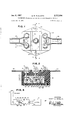
- Fig. l is a plan view of an embodiment of the invention.
- Fig. 2 is a longitudinal sectional view in elevation taken along the line 22 of Fig. 1, looking in the direction of the arrows;
- Fig. 3 is a bottom view of the embodiment of the invention shown in Fig. 1, with the bottom cover removed and with certain insulating compound omitted to illustrate details of construction;
- Fig. 4 is a transverse sectional view in elevation taken along the line 44 of Fig. 1, looking to the left in the direction of the arrows;
- Fig. 5 is a transverse sectional view in elevation taken along the line 5-5 of Fig. 1, looking to the right in the direction of the arrows, with a part of the insulating compound omitted;
- Fig. 6 is a schematic electrical circuit diagram showing the device of Figs. 1 to 5 connected in a transmission line between an antenna and the antenna terminals of a tele vision receiver.
- the device comprises a hollow main body or housing designated generally as 10.
- the hollow body 16 is formed of suitable electrical insulating material, as by molding or other convenient process.
- Five electrical terminals designated 11 to 15 are mounted on the body 10. These five terminals comprise two antenna terminals 11 and 12, a ground terminal 13, and two set terminals 14 and 15. The connections to these terminals are described in greater detail below.
- Each of these five terminals 11 to 15 comprises an acorn nut 16 disposed on the upper end of a threaded stud 17.
- the acorn nut 16 may be tightened or loosened at will to secure a conductor 18 against a fixed nut 19.
- a terminal lug 21 is held between upper and lower lock nuts 21 and 22-, respectively, carried by the threaded stud 17.
- the body is provided with laterally projecting ears 23 which have mounting holes 24 formed therein.
- An effectively coreless inductor or radio frequency choke coil 25 is disposed within the interior of the body 10.
- the inductor 25 is shown formed of a relatively few turns of heavy wire, the two ends of which are connected directly by soldering at 26 and 27 to antenna terminals 11 and 12.
- Coil 25 iscenter-tapped at 28 and'the center tap is connected to ground terminal 13.
- the in ductance of coil 25 is sufi'lciently high and its distributed capacitance is sufiiciently low so that the introduction of appreciable bridging loss in the transmission path from antenna terminals 11-, 12 to set terminals 14, 15 is etlectively avoided.
- a transverse barrier member 29 of suitable high voltage resistant dielectric material traverses the interior of body 10 between ground terminal 13 and set terminals 14 and 15.
- Four electrodes 30, 31, 32 and 33 are disposed on barrier member 29, and may be formed thereon by electroplating or electrodeposition, or may be secured thereto by suitable adhesive means.
- Juxtaposed electrodes 30 and 31 constitute a first coupling capacitor and similarly juxtaposed electrodes 32 and 33 constitute a second coupling capacitor.
- the barrier member 29 is positioned between inwardly extending lateral projections 34 formed on the inner wall of body
- a conductor 35 connects antenna terminal 11 through coupling capacitor 32, 33 to set terminal 14.
- a similar symmetrically arranged conductor 36 connects antenna terminal 12 through coupling capacitor 30, 31 to set terminal 15.
- a two-wire transmission line 37 of conventional construction extends from antenna terminals 11 and 12 to an antenna diagrammatically indicated as a dipole 38.
- a similar transmission line 39 extends from set terminals 14 and 15 to the antenna terminals 40 of a television or other signal receiver 41.
- the interior of body 10 and inductor 25 may be filled with a suitable insulating compound 42 to secure the various parts against movement relative to each other and to exclude moisture.
- the inductor 25 is completely surrounded by and imbedded in the insulating compound 42. This stabilizes the geometric configuration of inductor 25 and prevents small dimensional changes which could be produced by mechanical vibration and which could otherwise alter its inductance and distributed capacitance, thereby causing noticeable interference with the reproduced image in the case of a video signal.
- the compound 42 will be so selected that it will have satisfactory dielectric properties at the frequencies and voltages which are involved.
- the hollow body 10 may be closed at its bottom by a cover member 43 held by a screw 44.
- the antenna 38 is maintained at ground potential by the drainage connection to ground through ground terminal 13 and center tap 28 of coil 25.
- the inductance value for coil 25 and the capacitances of coupling capacitors 33 are selected to avoid resonance effects and to provide for the efficient transmission of signals from antenna 38 to the receiver 41, over the entire frequency range which is required to bereceived.
- the physical configuration of the circuitry is such as to minimize any impedance irregularity which may be introduced into the transmission line 37, 39 by the connection of the protective device therein.
- the protective device is connected in the transmission line 37, 39 at a point relatively close to the receiver 41.
- a protective device of the class described comprising a hollow body, a first pair of terminals mounted on said body and adapted for connection to an antenna, a second pair of terminals mounted on said body and adapted for connection to utilization means for a signal received by said antenna, a fifth terminal adapted to be connected to ground, a barrier of high voltage resistant insulating material extending transversely of the interior of said hollow body, said barrier having a first pair of electrodes disposed on one side thereof and a second pair of electrodes disposed on the opposite side thereof in juxtaposition to said first pair of electrodes, said tWo pairs of electrodes constituting a pair of direct current blocking coupling capacitors circuit means connecting said first pair of electrodes to said first pair of terminals and said second pair of electrodes to said second pair of terminals whereby said first pair of terminals is coupled to said second pair of terminals through said capacitors and a center-tapped inductor connected directly across said first pair of terminals, said inductor being conductive to direct current and disposed Within said body on the same side of said
Description
Jan. 8, 1957 s. M. WEISBERG 2,777,094
PROTECTIVE GROUNDING DEVICE FOR A HIGH FREQUENCY ANTENNA Filed Feb. 9, 1954 2 Sheets-Sheet l "6? Lou;
w rg
4| INVENTOR. f SIDNEY M. WEISBERG RECEIVER v 40 ATTORNEY Jan. 8, 1957 s. M. WEISBERG 2,777,094
PROTECTIVE GROUNDING DEVICE FOR A HIGH FREQUENCY ANTENNA Filed Feb. 9,.1954 2 Sheets-Sheet 2 INVENTOR. 29 42 43 SIDNEY M. WEISBERG A'f'TORN United States Patent PROTECTIVE'GROUNDING DEVICE FOR A HIGH FREQUENCY ANTENNA Sidney M. Weisberg, Maplewood,-N. 3., assignor to Allied Electric Products, Inc., Irvington, N. 1., a corporation of New Jersey Application February 9, 1954, Serial No. 409,103
1 Claim. (Cl. 317-61) The present invention relates to a grounding protective device for use with a high frequency antenna, such as a television antenna.
An object of the invention is to provide a grounding device which will effectively maintain the antenna at ground potential without impairing its efiiciency for the reception of signals.
A further object of the invention is the provision of a device of this character which will drain off undesired longitudinal currents and simultaneously pass the desired signal currents which are balanced with respect to ground.
Another object of the invention is to provide a protective device of this character for insertion in a transmission line with a minimum of ellect upon the normal characteristic impedance of the line.
Other and further objects and advantages of the invention will become apparent upon reading the following specification together with the accompanying drawing forming a part hereof.
Referring to the drawing:
Fig. l is a plan view of an embodiment of the invention;
Fig. 2 is a longitudinal sectional view in elevation taken along the line 22 of Fig. 1, looking in the direction of the arrows;
Fig. 3 is a bottom view of the embodiment of the invention shown in Fig. 1, with the bottom cover removed and with certain insulating compound omitted to illustrate details of construction;
Fig. 4 is a transverse sectional view in elevation taken along the line 44 of Fig. 1, looking to the left in the direction of the arrows;
Fig. 5 is a transverse sectional view in elevation taken along the line 5-5 of Fig. 1, looking to the right in the direction of the arrows, with a part of the insulating compound omitted;
Fig. 6 is a schematic electrical circuit diagram showing the device of Figs. 1 to 5 connected in a transmission line between an antenna and the antenna terminals of a tele vision receiver.
Referring to Fig. 1, the device comprises a hollow main body or housing designated generally as 10.
The hollow body 16 is formed of suitable electrical insulating material, as by molding or other convenient process. Five electrical terminals designated 11 to 15 are mounted on the body 10. These five terminals comprise two antenna terminals 11 and 12, a ground terminal 13, and two set terminals 14 and 15. The connections to these terminals are described in greater detail below. Each of these five terminals 11 to 15 comprises an acorn nut 16 disposed on the upper end of a threaded stud 17. The acorn nut 16 may be tightened or loosened at will to secure a conductor 18 against a fixed nut 19. At the lower or inner end of each terminal, a terminal lug 21) is held between upper and lower lock nuts 21 and 22-, respectively, carried by the threaded stud 17.
The body is provided with laterally projecting ears 23 which have mounting holes 24 formed therein.
'ice
An effectively coreless inductor or radio frequency choke coil 25 is disposed within the interior of the body 10. The inductor 25 is shown formed of a relatively few turns of heavy wire, the two ends of which are connected directly by soldering at 26 and 27 to antenna terminals 11 and 12. Coil 25 iscenter-tapped at 28 and'the center tap is connected to ground terminal 13. The in ductance of coil 25 is sufi'lciently high and its distributed capacitance is sufiiciently low so that the introduction of appreciable bridging loss in the transmission path from antenna terminals 11-, 12 to set terminals 14, 15 is etlectively avoided.
A transverse barrier member 29 of suitable high voltage resistant dielectric material traverses the interior of body 10 between ground terminal 13 and set terminals 14 and 15. Four electrodes 30, 31, 32 and 33 are disposed on barrier member 29, and may be formed thereon by electroplating or electrodeposition, or may be secured thereto by suitable adhesive means.
Juxtaposed electrodes 30 and 31 constitute a first coupling capacitor and similarly juxtaposed electrodes 32 and 33 constitute a second coupling capacitor. The barrier member 29 is positioned between inwardly extending lateral projections 34 formed on the inner wall of body A conductor 35 connects antenna terminal 11 through coupling capacitor 32, 33 to set terminal 14. A similar symmetrically arranged conductor 36 connects antenna terminal 12 through coupling capacitor 30, 31 to set terminal 15.
As shown in Figs. 1 and 6, a two-wire transmission line 37 of conventional construction extends from antenna terminals 11 and 12 to an antenna diagrammatically indicated as a dipole 38. A similar transmission line 39 extends from set terminals 14 and 15 to the antenna terminals 40 of a television or other signal receiver 41.
If desired, the interior of body 10 and inductor 25 may be filled with a suitable insulating compound 42 to secure the various parts against movement relative to each other and to exclude moisture. The inductor 25 is completely surrounded by and imbedded in the insulating compound 42. This stabilizes the geometric configuration of inductor 25 and prevents small dimensional changes which could be produced by mechanical vibration and which could otherwise alter its inductance and distributed capacitance, thereby causing noticeable interference with the reproduced image in the case of a video signal. The compound 42 will be so selected that it will have satisfactory dielectric properties at the frequencies and voltages which are involved. Conveniently, the hollow body 10 may be closed at its bottom by a cover member 43 held by a screw 44.
In operation, the antenna 38 is maintained at ground potential by the drainage connection to ground through ground terminal 13 and center tap 28 of coil 25. The inductance value for coil 25 and the capacitances of coupling capacitors 33 are selected to avoid resonance effects and to provide for the efficient transmission of signals from antenna 38 to the receiver 41, over the entire frequency range which is required to bereceived. As may be seen in the drawing, the physical configuration of the circuitry is such as to minimize any impedance irregularity which may be introduced into the transmission line 37, 39 by the connection of the protective device therein. Preferably, the protective device is connected in the transmission line 37, 39 at a point relatively close to the receiver 41.
What is claimed is:
A protective device of the class described, comprising a hollow body, a first pair of terminals mounted on said body and adapted for connection to an antenna, a second pair of terminals mounted on said body and adapted for connection to utilization means for a signal received by said antenna, a fifth terminal adapted to be connected to ground, a barrier of high voltage resistant insulating material extending transversely of the interior of said hollow body, said barrier having a first pair of electrodes disposed on one side thereof and a second pair of electrodes disposed on the opposite side thereof in juxtaposition to said first pair of electrodes, said tWo pairs of electrodes constituting a pair of direct current blocking coupling capacitors circuit means connecting said first pair of electrodes to said first pair of terminals and said second pair of electrodes to said second pair of terminals whereby said first pair of terminals is coupled to said second pair of terminals through said capacitors and a center-tapped inductor connected directly across said first pair of terminals, said inductor being conductive to direct current and disposed Within said body on the same side of said barrier as said first pair of electrodes, said center tap being connected to said fifth terminal for efiectively maintaining said first pair of terminals at ground potential with respect to said direct current.
References Cited in the file of this patent UNITED STATES PATENTS 617,170 Wilcox Jan. 3, 1899 1,547,242 Strieby July 28, 1925 1,728,534 Fortescue Sept. 17, 1929 1,861,183 Hough May 31, 1932 1,998,322 Kaar Apr. 16, 1935 2,666,908 Klostermann Ian. 19, 1954
Priority Applications (1)
| Application Number | Priority Date | Filing Date | Title |
|---|---|---|---|
| US409103A US2777094A (en) | 1954-02-09 | 1954-02-09 | Protective grounding device for a high frequency antenna |
Applications Claiming Priority (1)
| Application Number | Priority Date | Filing Date | Title |
|---|---|---|---|
| US409103A US2777094A (en) | 1954-02-09 | 1954-02-09 | Protective grounding device for a high frequency antenna |
Publications (1)
| Publication Number | Publication Date |
|---|---|
| US2777094A true US2777094A (en) | 1957-01-08 |
Family
ID=23619056
Family Applications (1)
| Application Number | Title | Priority Date | Filing Date |
|---|---|---|---|
| US409103A Expired - Lifetime US2777094A (en) | 1954-02-09 | 1954-02-09 | Protective grounding device for a high frequency antenna |
Country Status (1)
| Country | Link |
|---|---|
| US (1) | US2777094A (en) |
Cited By (4)
| Publication number | Priority date | Publication date | Assignee | Title |
|---|---|---|---|---|
| US2886744A (en) * | 1956-03-21 | 1959-05-12 | Jr William E Mcnatt | Electrical protective apparatus |
| US3938046A (en) * | 1974-10-21 | 1976-02-10 | Sarkes Tarzian, Inc. | Network for isolating antenna from tuner |
| US4335415A (en) * | 1980-02-07 | 1982-06-15 | Hooberry William D | Antenna lightning arrestor |
| US4901189A (en) * | 1988-06-24 | 1990-02-13 | American Telephone And Telegraph Company, At&T Technologies, Inc. | Terminal block and methods of making |
Citations (6)
| Publication number | Priority date | Publication date | Assignee | Title |
|---|---|---|---|---|
| US617170A (en) * | 1899-01-03 | Combined lightning-arrester and fusible cut-out | ||
| US1547242A (en) * | 1924-04-29 | 1925-07-28 | American Telephone & Telegraph | Carrier transmission over power circuits |
| US1728534A (en) * | 1927-08-08 | 1929-09-17 | Westinghouse Electric & Mfg Co | Telephone protective system |
| US1861183A (en) * | 1925-07-10 | 1932-05-31 | Wired Radio Inc | Radio reception system |
| US1998322A (en) * | 1933-04-29 | 1935-04-16 | Gen Electric | High frequency circuit |
| US2666908A (en) * | 1950-05-12 | 1954-01-19 | American Phenolic Corp | Lightning arrester |
-
1954
- 1954-02-09 US US409103A patent/US2777094A/en not_active Expired - Lifetime
Patent Citations (6)
| Publication number | Priority date | Publication date | Assignee | Title |
|---|---|---|---|---|
| US617170A (en) * | 1899-01-03 | Combined lightning-arrester and fusible cut-out | ||
| US1547242A (en) * | 1924-04-29 | 1925-07-28 | American Telephone & Telegraph | Carrier transmission over power circuits |
| US1861183A (en) * | 1925-07-10 | 1932-05-31 | Wired Radio Inc | Radio reception system |
| US1728534A (en) * | 1927-08-08 | 1929-09-17 | Westinghouse Electric & Mfg Co | Telephone protective system |
| US1998322A (en) * | 1933-04-29 | 1935-04-16 | Gen Electric | High frequency circuit |
| US2666908A (en) * | 1950-05-12 | 1954-01-19 | American Phenolic Corp | Lightning arrester |
Cited By (4)
| Publication number | Priority date | Publication date | Assignee | Title |
|---|---|---|---|---|
| US2886744A (en) * | 1956-03-21 | 1959-05-12 | Jr William E Mcnatt | Electrical protective apparatus |
| US3938046A (en) * | 1974-10-21 | 1976-02-10 | Sarkes Tarzian, Inc. | Network for isolating antenna from tuner |
| US4335415A (en) * | 1980-02-07 | 1982-06-15 | Hooberry William D | Antenna lightning arrestor |
| US4901189A (en) * | 1988-06-24 | 1990-02-13 | American Telephone And Telegraph Company, At&T Technologies, Inc. | Terminal block and methods of making |
Similar Documents
| Publication | Publication Date | Title |
|---|---|---|
| US3980976A (en) | Coaxial connector | |
| US4144509A (en) | Filter connector | |
| US4329665A (en) | Noise suppressing connector | |
| US4229714A (en) | RF Connector assembly with provision for low frequency isolation and RFI reduction | |
| JP2515624B2 (en) | Antenna coupling circuit | |
| JPH05283126A (en) | Connector | |
| US5476394A (en) | Antenna connector | |
| US2403349A (en) | Combination coil and condenser | |
| US4267529A (en) | TV antenna isolation system | |
| US4631506A (en) | Frequency-adjustable coaxial dielectric resonator and filter using the same | |
| US2829367A (en) | Television lead-in coupler | |
| US3597711A (en) | Removable electrical connector filter | |
| US2777094A (en) | Protective grounding device for a high frequency antenna | |
| US5019830A (en) | Amplified FM antenna with parallel radiator and ground plane | |
| GB2148604A (en) | Monopole aerial | |
| US5351018A (en) | Antenna isolation assembly for hot chassis receiver | |
| US2835874A (en) | Electrical interference suppression filter | |
| US2323628A (en) | Art of mounting electron discharge devices | |
| KR940010002B1 (en) | Signal input device | |
| US3087126A (en) | Coaxial attenuation equalizer | |
| US4790030A (en) | Tuner with insertable antenna coupler | |
| JPH0134403Y2 (en) | ||
| KR0151582B1 (en) | Coaxial cable terminator and its method | |
| JPS6246356Y2 (en) | ||
| NO170180B (en) | COAXIAL TYPE ELECTRIC LOW PASS FILTER |