US2777078A - Electrostatic high tension generator - Google Patents
Electrostatic high tension generator Download PDFInfo
- Publication number
- US2777078A US2777078A US472130A US47213054A US2777078A US 2777078 A US2777078 A US 2777078A US 472130 A US472130 A US 472130A US 47213054 A US47213054 A US 47213054A US 2777078 A US2777078 A US 2777078A
- Authority
- US
- United States
- Prior art keywords
- charge
- carrying surfaces
- carrying
- spray discharge
- discharge members
- Prior art date
- Legal status (The legal status is an assumption and is not a legal conclusion. Google has not performed a legal analysis and makes no representation as to the accuracy of the status listed.)
- Expired - Lifetime
Links
Images


Classifications
-
- H—ELECTRICITY
- H02—GENERATION; CONVERSION OR DISTRIBUTION OF ELECTRIC POWER
- H02N—ELECTRIC MACHINES NOT OTHERWISE PROVIDED FOR
- H02N1/00—Electrostatic generators or motors using a solid moving electrostatic charge carrier
- H02N1/06—Influence generators
- H02N1/10—Influence generators with non-conductive charge carrier
Definitions
- This invention relates to a generator for producing electrostatic high tension and has special reference to an electrostatic generator or influence machine comprising two charge-carrying disks of insulating material rotating in opposite directions. Such machines have been known since the generation of electricity has been dealt with, but they have never found any large scale technical application.
- the two charge-carrying surfaces are disposed very closely adjacent to each other and have the shape of the superficies of bodies generated by rotation and are moved in an approximately homogeneous electric field disposed at an inclined angle to their surface.
- the ionizing or spray discharge members between which the charge-carrying surfaces rotate are mutually displaced in the direction of motion of the charge-carrying surfaces coordinated to them, by an amount corresponding approximately to the magnitude of the thickness of the two charge-carrying surfaces.
- These spray discharge members are opposed to electrodes serving for initial excitation and simultaneously for screening the spray discharge members towards the main field.
- the approximately homogeneous electric field in which the charge-carrying surfaces move is formed mainly by the surfaces of conductors facing the running-out chargecarrying surfaces. These surfaces of the conductors are geometrically similar to the surfaces of the charge-carrying surfaces. The two surfaces form between each other an angle which is smaller than 90, its actual size depending upon the arrangement and the materials of the charge-carrying surfaces and of the conductors and upon the qualities of the surrounding gas or liquid.
- the mutual distance of the charge-carrying surfaces is advantageously made so small that the breakdown field strength in the medium in which the field extends between the charge-carrying surfaces, is substantially higher than its normal value.
- the electrodes opposed to the spray discharge or ionizing members and serving for initial excitation and screening against the main field may be fitted with their own small spray discharge members charging these electrodes during operation.
- These small spray discharge members of the electrodes are arranged in the region between the spray discharge members of the conductors and the electrodes at the point where charges of same sign are 0pposed to each other on the two charge-carrying surfaces.
- the generator is fitted with a plurality of electrodes arranged along the charge-carrying surfaces with alternate signs, the number of the poles being an integral multiple of two.
- the electrodes serving for the initial excitation are in direct communication with each other. However, it is 2,777,078 Patented Jan. 8, 1957 also possible to interconnect them by high ohmic resistances which are dimensioned accordingly.
- the entire apparatus producing the electrostatic high tension is arranged between two plates or hollow bodies which as to their shape are geometrically similar to the shape of the charge-carrying surfaces, extend in a parallel direction to the charge-carrying surfaces and are provided to support the conductors and electrodes.
- These plates or hollow bodies must be made of a material of a sufficiently high mechanical and electrical strength.
- One of the two charge-carrying surfaces is preferably fixedly connected to the driving shaft While the other one is driven from the same shaft in an opposite direction, through a planetary gear.
- the plates or hollow bodies constructed as carrier elements or supports for the conductors and electrodes may simultaneously be constructed for the reception of the ball bearings for the shaft, thus supporting the entire arrangement.
- the same may be equipped with a passing shaft.
- the driving motor together with the generator is arranged within a pressure casing; hereat, the shaft of the driving motor may be simultaneously the shaft of the apparatus serving for producing the high tension.
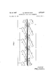
- Fig. l is a diagrammatic view showing the connections and the charging scheme of an electrostatic high tension generator having the invention applied thereto,
- Fig. 2 is an elevation showing one half of the charging equipment
- Fig. 3 is a side view thereof
- Fig. 4 is an axial section through a practical embodiment of the generator
- Fig. 5 is an axial section thereof
- Fig. 6 is a radial section of a further modification.
- the negatively charged conductors 2 are fitted with spray discharge members 4 and the positively charged conductors 3 are fitted with spray discharge members 5.
- These spray discharge members are mutually staggered, in the direction of motion of the charge-carrying surfaces associated to them, approximately by an amount corresponding to the thickness of the two charge-carrying surfaces.
- Electrodes 6 Arranged vis-a-vis to the spray discharge members 4 of the negatively charged conductors 2 are electrodes 6 having an even higher negative charge, and similarly vis-a-vis to the spray discharge members 5 of the positively charged conductors 3 there are arranged electrodes 7 having a still higher positive charge, said electrodes serving for initial excitation.
- These electrodes '6 and 7 in their turn have their own small spray discharge memarmors bers 8 and 9 arranged in the region between the respective corresponding spray discharge members 4 or 5. In this range, the two charge-carrying surfaces always have the same negative or positive charge.
- the signs of the respective charges on the chargecarrying surfaces, conductors and electrodes are marked by the signs (positive) and (negative).
- the two closely adjacent charge-carrying surfaces 1 of insulating material rotate in opposite directions and at a high speed in an approximately homogeneous electrical field, which, as will be seen from the drawing, is directed at an oblique angle to their surface.
- the chargecarrying surfaces have no metallic coating.
- the maximum voltage of the electrostatic high tension generator is obtained by suitable shaping of the con ductors.
- This voltage is represented by the line integral over the field strength between the ne atively and positively charged conductors.
- This electric field strength in turn can nowhere be higher than the breakdown field strength of the medium disposed between the conductors. It follows that the maximum field strength and thus the maximum voltage can be reached if the field between the conductors is homogeneous. Hitherto it had been attempted to attain an at least approximate homogenisation by arranging between the conductors as many further surfaces as possible, whose potential was controlled by potentiometers, or by connecting the conductors by semi conducting layers acting as potentiometers themselves.
- each conductor facing the running-out charge-carrying surface has a shape which is geometrically similar to the charge-carrying surface.
- the conductors have the shape of planes with smoothly rounded edges and are as much as possible arranged parallel to each other.
- the conductors also have the shape of sectors of cylindrical superficics, again with thoroughly rounded edges, always a pair of conductors opposed to each other being arranged coaxial.
- the most favorable angle between the conductor surfaces and the charge-carrying surfaces is given by the sinus thereof which is given as the ratio of the field strength of the creeping discharge, i. e., the maximum tangential field strength on the charge-carrying surface and the breakdown field strength in the surrounding medium.
- E3 sin a charge-carrying surfaces, Er being the creeping discharge field strength, and Ed being the breakdown field strength of the surrounding medium. It follows that the angle at is a function both of the condition of the surrounding medium and its pressure, and of the condition of the charge-carrying surfaces.
- the two spray discharge members of the two conductors of a pole are relatively displaced by an amount of the order of the thickness of the two charge-carrying surfaces in the direction of motion of the charge-carrying surfaces associated to them, so that the charge of one carrier surface has an influencing effect upon the spray discharge member associated to the other charge-carrying surface, before this charge is taken off at the spray discharge member associated to it and replaced by one of opposite sign.
- these spray discharge members are arranged in such a way that the main field, i. e. the field between the conductors, cannot act upon them, but that only the charging field causes its spray discharge.
- the current intensity of the generator is multiplied accordingly.
- a reduction of the voltage takes place, since the pole units succeed each other at shorter intervals.
- the output of the generator is nearly independent of the number of poles.
- the distance between the charge-carrying surfaces is made as small as possible, whereby the breakdown voltage in the medium which exists between them, and in which the charging field extends, is substantially increased compared to the normal value. Since the breakdown field strength of this intermediate layer simultaneously is the maximum charging field strength, it limits the density of charge on the charge-carrier surfaces and thus the current. Hence, it is of extreme importance to keep this breakdown field strength as high as possible.
- the electrodes 6, in this case assumed to be negative, serving simultaneously for feeding an initial exciting voltage from the outside, are conductively connected with each other. At the beginning, they are charged with a negative potential from the outside for a short time. After one revolution of the charge-carrying surfaces the generator operates automatically without an auxiliary voltage from the outside, since the charges then form the charging field on the charge-carrying surfaces and ensure the further continuity of the excitation. They can as well be excited with a positive potential. This merely would result in a change of the sign of the entire distribution of the charge.
- the charge-carrying surfaces are discharged in the main field, whereby the excitation would fade.
- This is counteracted by reinforcing the charging field in the region of the spray discharge members of the conductors by the electrodes opposed to the same, which electrodes are automatically charged with a corresponding sign by their small spray discharge members which are located in the region between the spray discharge members of the conductors at the points where charges of same sign are opposed to each other on the two charge-carrying surfaces.
- the electrodes screen the spray discharge members of the conductors against the main field, whereby it is ensured that the current, as mentioned above, is independent of the voltage.
- the negative or the positive conductors are conductively connected to each other.
- the respective conductors are led to the outside and serve for taking the high tension produced in the generator.
- Fig. 2 shows in elevation one half of the charging system diagrammatically indicated in Fig. l for an electrostatic high tension generator in which the charge-carrying surfaces take the shape of plane circular discs
- Fig. 3 shows the same in a side view.
- the conductors 2 and 3 Secured on suitably shaped projections 11 of thick circular discs of a material of a sulficiently high mechanical and electrical strength are the conductors 2 and 3 as well as the electrodes 6 and 7. It will be clearly seen from these figures that the geo; ietrical shape of the conductors 2 and 3 is assimilated as much as possible to the shape of the charge-carrying surfaces.
- a pair of such charging systems in which each time the conductors 2 and 3 are opposed to each other, to gether with the charge-carrying surfaces running therebetween form the complete charging system of an electrostatic high tension generator in accordance with the invention.
- Fig. 4 shows an embodiment of the high tension generator comprising a charging system of the type shown in Figs. 2 and The high tension generator is shown in an axial section, the part separated from the rest of the drawing by the line ⁇ -1 being an axial section turned through 90.
- a circular chargecarrying surface 13 of glass or another insulating material which in turn is secured on a hub member 14 consisting of a material of a high mechanical and dielectric strength, preferably a synthetic plastic.
- a plastic which in a liquid state simultaneously can be used as an adhesive with the aid of which the disc can be secured on the annular hub member 14 which is connected with a hub 16 of the same material by six screws 15.
- the hub 16 in turn is fixedly secured to the shaft 12 and secured against turning by a pin 17.
- the charge-carrying disc 18 working in opposite direction is secured, the same as the disc 13, on an annular member 19, which in its turn is secured by six screws 2% on a hub 21 of the same synthetic plastic, accommodating in a coaxial bore two ball bearings 22 and 23 which are slipped on the shaft 12.
- the ball bearing 22 is of the type having race rings whose races are opposed to each other in an inclined direction, so as to be able to receive the axial pull caused by the electrostatic attraction between the two chargecarrying surfaces 13 and 18.
- the hub 21 carries a bevel wheel 24 forming part of a planetary gear including a further bevel wheel 25 fixedly secured on the shaft 12, and a pair of bevel wheels 27, only one of which is shown in tr e drawing.
- the bevel wheels 24 and 25 may consist of a suitable synthetic plastic.
- the two bevel wheels 27 consist of steel and run on ball bearings, in milled-out recesses of the metallic member 28 which is secured by means of six screws 29, on a circular plate 30 of a material of a sufficiently high mechanical and dielectric strength whose opposite side carries the charging system (not shown).
- the member 28 simultaneously serves for accommodating one of the ball bearings 31, while the second ball bearing 32 is accommodated in a further circular plate 10 of the same material as the plate 30 which is connected to the plate 29 by six threaded spacing bolts 33.
- the electrically insulating members more particularly the hubs 16 and 21, the annular members 14 and 19, and the two plates 19 and 30 of the embodiment shown in the drawing may be made of a synthetic plastic of a suitable type.
- Both the two ball bearings '22 and 23 of the hub of the charge-carrying surface working in an opposite direction and the ball bearing 32 may be inserted in the hub "or in the plate 19, consisting for instance, of a material known under the trade name of Araldit, without a metallic tin ing.
- the four ball bearings are held in position by l red for an internal pressure of about 45 atmospheres on the pressure gauge.
- the end plate 37 is formed at its periphery with a circular recess for reception of a packing ring 40.
- the recess is bevelled in such a way that the packing ring id is forced into the tapering interspace between the cylinder 35 and the end plate 37, for improving the packing et fect.
- the packings 84 between the shaft 12 and the end plates 36 and 37 are commercial flanged or hat-shaped ring packings held in position by ring members 85, 86, and 87, respectively, which are secured to the plates 36 or 37 by screws 8?.
- the pressure-tight leading-in bushings for the high-tension cables 41 which preferably consist of pol ethylene-insulated cables, are advantageously obtained by casting a cold-setting plastic such as the above mentioned Araldit material into the space 43, after the cable has been fixed in position by a plate 42 of Araldit secured on the plate 37 by screws 39 and by an adhesive.
- the complete interior part of the machine, supported by the two thick plates 16 and 39 of Araldit, may be fixed in axial and radial directions by means of rubber bolts which have not been shown, for the sake of clarity.
- Fig. 5 is an axial section of a further constructional form of the electrostatic high tension generator according to the invention, and Fig. 6 is a radial section thereof, on the line Vl-Vt of Fig. 5.
- charge-carrying surfaces 44 and 45 taking the shape of the surface of a cylinder are used, accordingly the conductors 46 and d7 conform to this shape, so as to ensure as much as possible a homogeneous main field at the point where the same is traversed by the charge-carrying surfaces 44.
- the entire equipment serving for the production of the direct voltage is accommodated between two stationary cylinders and 49 of a material of a sufficiently high dielectric and mechanical strength. These cylinders are screwed on a plate 5d of the same material, but they may as well be secured thereon by gluing.
- the plate 50 is secured on the end face of a driving motor 551 of adjustable speed which in this embodiment is accommodated within the pressure vessel 52.
- the extended shaft 53 of this driving motor 51 simultaneously serves as a shaft for the high tension generator.
- the external rotating charge-carrying cylinder 4 5 is fixedly secured on this driving shaft 53, while the internal charge-carrying cylinder 45 is driven by the same driving shaft S3 through a planetary gear 54 in an opposite direction, and mounted on the same shaft by means of ball bearings :35 and as.
- the planeatry gear 54. is disposed within the internal stationary cylinder 49.
- the conductors 45 and 3-7 take the form of parts of the surface of a cylinder, with Well-rounded edges, and are arranged in such a way that the mutually opposed conductors are coaxially arranged. However, their shaft does not coincide with the axis of rotation of the cylindrical charge -carrying surfaces 44 and 45.
- the conductors 46 and 47 and the electrodes 57 and 58 are secured by means of screws 59 on carrier barsfi't) and 61 which in turn are secured, by means of screws '79, on the stationary external and internal cylinders 48 and -49 of insulating material. Inserted between the carrier bars and 61, the conductors, and the electrodes are pads 62 of a plastic armors 7 insulating material, e. g. rubber, for permitting adjust ment of the conductors and electrodes.
- the end plate 50 and an annular member 63 supporting the driving motor 51 in relation to the pressure vessel 52 which has the shape of a cylinder with put-on spherical calotte, serve to fix the generator system in the pressure vessel 52.
- the driving motor 51 is accommodated on the side of the pressure Vessel terminating in said spherical calotte.
- this spherical calotte in the extension of the shaft of the generator-motor system includes a valve 64 for filling the vessel with compressed
- the opposite end of the pressure cylinder 52 is closed by an end plate 65 which is held in position by an externally threaded ring 66 screwed into a female thread of the steel cylinder 52.
- the current intensity can be multiplied by connecting several machines in parallel, and the voltage can be multiplied by connecting several machines in series. Especially in the latter case it may be desirable to effect the drive of all machines by a single motor which is on ground potential.
- the constructional embodiment shown in Fig. 4- is particularly adapted.
- the transmission of the torque from one machine to the adjacent one again is effected by coupling members of insulating material. These insulating coupling members must insulate the voltage existing between two consecutive machines.
- a generator for producing an electrostatic high tension comprising a pair of bodies of rotation of insulating material adapted to be rotated at a high rate of speed, in opposite directions, and forming a pair of charge-carrying surfaces arranged closely adjacent to each other, means for producing an approximately homogeneous electric field directed at an oblique angle to the charge-carrying surfaces, pairs of spray discharge members arranged on opposite sides of the charge-carrying surfaces so as to be displaced in relation to each other, in the direction of motion of the charge-carrying surface associated to each of them, by an amount which is not substantially different from the total thickness of the two bodies forming the charge-carrying surfaces, and electrodes opposed to the spray discharge members for initial excitation and simultaneously for screening the spray discharge members against the main field.
- a generator for producing an electrostatic high tension comprising a pair of bodies of rotation of insulating material adapted to be rotated at a high rate of speed, in opposite directions, and forming a pair of chargecarrying surface arranged closely adjacent to each other, means including conductors Whose surfaces directed towards the running out charge-carrying surfaces are geometrically similar to the charge-carrying surfaces and form with the charge-carrying surfaces an angle of less than 90, for producing an approximately homogeneous electric field directed at an oblique angle to the chargecarrying surfaces, pairs of spray discharge members arranged on opposite sides of the charge-carrying surfaces so as to be displaced in relation to each other in the direction of motion of the charge-carrying surface associated to each of them, by an amount which is not substantially different from the total thickness of the two charge-carrying surfaces, and electrodes opposed to the spray discharge members for initial excitation and simultaneously for screening the spray discharge members against the main. field.
- a generator for producing an electrostatic high ten-- sion comprising a pair of bodies of rotation of insulating. material adapted to be rotated at a high rate of speed, in opposite directions, and forming a pair of charge-carry ing surfaces arranged closely adjacent to each other, the.
- interspace between said charge-carrying surfaces being so small that the breakdown voltage in the medium between them, where the charging field extends, is increased sub stantially over the normal value, means for producing an approximately homogeneous electric field directed at an oblique angle to the charge-carrying surfaces, pairs of spray discharge members arranged on opposite sides of the charge-carrying surfaces so as to be displaced in rela tion to each other in the direction of motion of the chargecarrying surface associated to each of them, by an amount which is not substantially different from the total thickness of the two bodies forming the charge-carrying surfaces, and electrodes opposed to the spray discharge members for initial excitation and simultaneously for screening the spray discharge members against the main field.
- a generator for producing an electrostatic high tension comprising a pair of closely adjacent charge-carrying surfaces of insulating material shaped as surfaces of bodies of rotation adapted to be rotated at a high speed, in opposite directions, means for producing an approximately homogeneous electric field directed at an oblique angle to the charge-carrying surfaces, pairs of spray discharge members arranged on opposite sides of the chargecarrying surfaces so as to be displaced in relation to each other in the direction of motion of the charge-carrying surface associated to each of them, by an amount which is not substantially different from the total thickness of the two bodies forming the charge-carrying surfaces, and electrodes opposed to the spray discharge members for initial excitation and simultaneously for screening the spray discharge members against the main field, said electrodes being provided with their own small spray discharge members which are adapted to charge the electrodes during operation.
- a generator for producing an electrostatic high tension comprising a pair of bodies of rotation of insulating material adapted to be rotated at a high rate of speed, in opposite directions, and forming a pair of chargecarrying surfaces arranged closely adjacent to each other, means for producing an approximately homogeneous electric field directed at an oblique angle to the charge carrying surfaces, pairs of spray discharge members ar ranged on opposite sides of the charge-carrying surfaces so as to be displaced in relation to each other in the direction of motion of the charge-carrying surface associated to each of them, by an amount which is not substantially ditfcrent from the total thickness of the two bodies forming the charge-carrying surfaces, and electrodes opposed to the spray discharge members for initial excitation and simultaneously for screening the spray discharge members against the main field, said electrodes being provided with their own small spray discharge members which are located in the region between the spray discharge members of the conductors and the electrodes, at the points where charges of the same sign are opposed to each other, for charging the electrodes during operation.
- a generator for producing an electrostatic high tension comprising a pair of bodies of rotation of. insulating material adapted to be rotated at a high rate of speed, in opposite directions, and forming a pair of chargecarrying surfaces arranged closely adjacent to each other, a plurality of poles arranged along the charge-carrying surfaces with alternate sign, the number of such poles being an integral multiple of two and each pole comprising a pair of conductors whose surfaces directed towards the running out charge-carrying surfaces a'regeometrically similar to the charge-can-ying surfaces and form therewith an angle of lessthzxn 90, a pair of spray discharge members arranged on opposite sides of the chargecarrying surfaces so as to be displaced in relation to each other, in the direction of motion of the charge-carrying surface associated to each of them, by an amount which is not substantially different from the total thickness of the two bodies formingthe charge-carrying surfaces, a pair of electrodes opposed to the spray discharge members for initial excitation and simultaneously for screening the spray discharge members against
- a generator for producing an electrostatic high tension comprising a pair of bodies of rotation of insulat' ing material adapted to be rotated at a high rate of speed, in opposite directions, and forming a pair of charge carrying surfaces arranged closely adjacent to each other, means for producing an approximately homogeneous electric field directed at an oblique angle to the chargecarrying surfaces, pairs of spray discharge members arranged on opposite sides of the charge-carrying surfaces so as to be displaced in relation to each other, in the direction of motion of the charge-carrying surface associated to each of them, by an amount which is not substantially different from the total thickness of the two bodies forming the charge-carrying surfaces, electrodes opposed to the spray discharge members for initial excitation and simultaneously for screening the spray discharge members against the main field, and high ohmic resistances interconnecting said electrodes.
- a generator for producing an electrostatic high tension comprising a pair of bodies of rotation of insulating material adapted to be rotated at high rate of speed, in opposite directions, and forming a pair of chargecarrying surfaces arranged closely adjacent to each other, means for producing an approximately homogeneous electric field directed at an oblique angle to the chargecarrying surfaces, pairs of spray discharge members arranged on opposite sides of the charge-carrying surfaces so as to be displaced in relation to each other, in the direction of motion of the charge-carrying surface associated to each of them, by an amount which is not substantially different from the total thickness of the two bodies forming the charge-carrying surfaces, and elec trodes opposed to the spray discharge members for initial excitation and simultaneously for screening the spray discharge members against the main field said electrodes being not conductively connected with each other.
- a generator for producing an electrostatic high 'tension comprising a pair of bodies of rotation of insulating material adapted to be rotated at a high rate of speed, in opposite directions, and forming a pair of chargecarrying surfaces arranged closely adjacent to each other, means including conductors whose surfaces directed towards the running out charge-carrying surfaces are geometrically similar to the charge-carrying surfaces and form with the charge-carrying surfaces an angle of less than 90, for producing an approximately homogeneous dielectric field directed at an oblique angle to the chargecarrying surfaces, pairs of spray discharge members arranged on opposite sides of the charge-carrying surfaces so as to be displaced in relation to each other in the direction of motion of the charge-carrying surface associated to each of them, by an amount which is not substantially different from the total thickness of the two charge-carrying surfaces, electrodes opposed to the spray discharge members for initial excitation and simultaneously for screening the spray discharge members against the main field, and a pair of plates of sufiicient mechanical and dielectric strength which are geometric
- a generator for producing an electrostatichigh tension comprising a generator system including a pair of bodies of rotation of insulating material adapted to be rotated at a high rate of speed, in opposite directions, and forming a pair of charge-carrying surfaces arranged closely adjacent to each other, a driving shaft-on which one of said bodies is fixedly mounted, two ball bearings by which the other one of said bodies is rotatably mounted on said shaft, '2 planetary-gear driving said other body in an opposite direction, means for producing an approximately homogeneous electric field directed at an oblique angle to the charge-carrying surfaces, pairs of spray discharge members-arranged on opposite sides of the charge-carrying surfaces so-as to be displaced in relation to each other, in the direction of motion of the charge-carrying surface associated to each of them, by an amount which is not substantially different from the total thickness of the two bodies forming the chargecarrying surfaces, and electrodes opposed to the spray discharge members for initial excitation and simultaneously for screening the spray discharge members against
- a generator for producing an electrostatic high tension comprising a pair of bodies of rotation of insulating material adapted to be rotated at a high rateof speed, in opposite directions, and forming a pair of charge-carrying surfaces arranged closely adjacent to each other, a driving shaft on which one of said bodies is fixedly mounted, two ball bearings by whichthe other one of said bodies is rotatably mouthed on said shaft, a planetary gear driving said other 'body in an opposite direction, means including conductors whose surfacesdirected towards the running out charge-carrying surfaces are geometrically similar to the charge-carrying surfaces and form with the charge-carrying surfaces an angle of less than for producing an approximately homogeneous electric field directed at an oblique angle to the charge-carrying surfaces, pairs -of spray discharge members arranged on opposite sides of the charge-carrying surfaces so as to be displaced in relation to each other in the direction of motion of the charge-carrying surface associated to each of them, by an amount which is not substantially different from the total thickness of
- a generator for producing an electrostatic high tension comprising a generator system including a pair of bodies of rotation of insulating material adapted to be rotated at a high rate of speed, in opposite directions, and forming a pair of charge-carrying surfaces arranged closely adjacent to each other, a driving shaft on which one of said bodies is fixedly mounted, two ball bearings by which the other one of said bodies is rotatably mounted on said shaft, one of said ball bearings being an angular ball bearing adapted to take up radial bearing pressures and axial bearing pressures caused by electrostatic attraction between the two charge-carrying surfaces, a planetary gear driving said other body in an opposite direction, means for producing an approximately homogeneous electric field directed at an oblique angle to the chargecarrying surfaces, pairs of spray discharge members arranged on opposite sides of the charge-carrying surfaces so as to be displaced in relation to each other, in the direction of motion of the charge-carrying surface associated to each of them, by an amount which is not substantially different from the total thickness of the generator
- a generator for producing an electrostatic high tension comprising a pair of bodies of rotation of glass adapted to be rotated at a high rate of speed, in opposite directions, and forming a pair of charge-carrying surfaces arranged closely adjacent to each other, hub members for said bodies which hub members consist of a material of sufficient mechanical and electrical strength which at the same time, in a liquid form, serves as an adhesive for connecting said bodies to said hubs, means for producing an approximately homogeneous electric field directed at an oblique angle to the charge-carrying surfaces, pairs of spray discharge members arranged on opposite sides of the charge-carrying surfaces so as to be displaced in relation to each other, in the direction of motion of the charge-carrying surface associated to each of them, by an amount which is not substantially different from the total thickness of the two bodies forming the charge-carrying surfaces, and electrodes opposed to the spray discharge members for initial excitation and simultaneously for screening the spray discharge members against the main field.
- a generator for producing an electrostatic high tension comprising a generator system including a pair of bodies of rotation of insulating material adapted to be rotated at a high rate of speed, in opposite directions, and forming a pair of charge-carrying surfaces arranged closely adjacent to each other, a driving shaft on which one of said bodies is fixedly mounted, two ball bearings by which the other one of said bodies is rotatably mounted on said shaft, a planetary gear driving said other body in an opposite direction, means for producing an approximately homogeneous electric field directed at an oblique angle to the charge-carrying surfaces, pairs of spray discharge members arranged on opposite sides of the chargecarrying surfaces so as to be displaced in relation to each other, in the direction of motion of the charge-carrying surface associated to each of them, by an amount which is not substantially different from the total thickness of the two bodies forming the charge-carrying surfaces, and electrodes opposed to the spray discharge members for initial excitation and simultaneously for screening the spray discharge members against the main field, said shaft projecting from the generator
- a high tension generator comprising a pair of bodies of rotation of insulating material adapted to be rotated at a high rate of speed, in opposite directions, and forming a pair of charge-carrying surfaces arranged closely adjacent to each other, means for producing an approximately tomogeneous electric field directed at an oblique angle to the charge-carrying surfaces, pairs of spray discharge members arranged on opposite sides of the charge-carrying surfaces so as to be displaced in relation to each other, in the direction of motion of the charge-carrying surfaces associated to each of them, by an amount which is not substantially different from the total thickness of the two bodies forming the charge-carrying surfaces, and electrodes opposed to the spray discharge members for initial excitation and simultaneously for screening the spray discharge members against the main field.
- a generator arnangement for producing an electr-ost-atic high tension a pressure vessel and, accommodated therein, a driving motor and a high tension generator having a common shaft with said driving motor and comprising a pair .of bodies of rotation of insulating material adapted to the rotated at a high rate of speed, in opposite directions, and forming a pair of charge-carrying surfaces arranged closely adjacent to each other, means for producing an approximately homogeneous electric field directed at an oblique angle to the chargecarrying surfaces, pairs of spray discharge membens arranged :on opposite sides of the charge-carrying surfaces so as to be displaced in relation to each other, in the direction of motion of the charge-carrying surface associated to each .of them, by an amount which is not substantially different from the total thickness of the two bodies forming the charge-carrying surfaces, and elec trodes opposed to the spray discharge members for initial excitation and simultaneously for screening the spray discharge membens against the main field.
- a generator for producing an electrostatic high tension comprising a pair of bodies of rotation of insulating material adapted to be rotated at a high rate of speed, in opposite directions, and forming a pair of cylindnically shaped charge-carrying surfaces, pairs of spray discharge members arranged on opposite sides of the charge-carrying surfaces so as to be displaced in [relation to each other, in the direction of motion of the chargecarrying surface associated to each of them, by an amount which is not substantially different from "the total thickness of the two bodies forming the charge-carrying surfaces, and electrodes opposed to the spray discharge members for initial excitation and simultaneously for screening the spray discharge members against the main field.
- a generator for producing an electrostatic high tension comprising a pair of bodies of rotation of insulating material adapted to be rotated at a high rate of speed, in opposite directions, and forming a pair of cylindrically shaped charge-carrying surfaces arranged closely adjacent to each other, means including conductors whose surfaces directed towards the running out charge carrying surfaces are geometrically similar to the chargecarrying surfaces and form with the charge-carrying surfaces an angle of less than for producing an apapproxima-tely homogeneous electric field directed at an oblique angle to the charge-carrying surfaces, pairs of spray discharge members arranged on opposite sides of the charge-carrying surfaces so as to be displaced in relation to each other in the direction of motion of the charge-carrying surface associated to each of them, by an amount which is not substantially different from the total thickness of the two charge-carrying surfaces, electrodes opposed to the spray discharge members for initial excitation and simultaneously for screening the spray discharge members against the main field, and a pair of cylindrical shells of sufficient mechanical and dielectric strength
Description
Jan. 8, 1957 w. HERCHENBACH 2,777,073-
ELECTROSTATIC HIGH TENSION GENERATOR Filed Nov. 30, 1954 5 Shee'ts-Sheet 1 Jan. 8, 1957 w. HERCHENBACH 2,777,073
ELECTROSTATIC HIGH TENSION GENERATOR Filed Nov. 30, 1954 5 Sheets-Sheet 2 5 Sheets-Sheet 3 Filed Nov. 30. 1954 Jan. 8, 1957 w. HERCHENBACH 2,777,078
ELECTROSTATIC HIGH TENSION GENERATOR www Jan. 8, 1957 w, HERCHENBACH 2,777,078
ELECTROSTATIC HIGH TENSION GENERATOR Filed Nov. 50, 1954 5 Shets-'iheet 5 United States Patent ELECTROSTATIC HIGH TENSION GENERATOR Wolfgang Herchenbach, Tubingen, Germany Application November 30, 1954, Serial No. 472,130
18 Claims. (Cl. 310--6) This invention relates to a generator for producing electrostatic high tension and has special reference to an electrostatic generator or influence machine comprising two charge-carrying disks of insulating material rotating in opposite directions. Such machines have been known since the generation of electricity has been dealt with, but they have never found any large scale technical application.
It is an object of the present invention to improve the efficiency of such machines by a special construction and arrangement of the spray discharge members, conductors, electrodes, and charge-carrying surfaces.
With this and further objects in view, according to the present invention the two charge-carrying surfaces are disposed very closely adjacent to each other and have the shape of the superficies of bodies generated by rotation and are moved in an approximately homogeneous electric field disposed at an inclined angle to their surface. Moreover, the ionizing or spray discharge members between which the charge-carrying surfaces rotate, are mutually displaced in the direction of motion of the charge-carrying surfaces coordinated to them, by an amount corresponding approximately to the magnitude of the thickness of the two charge-carrying surfaces. These spray discharge members are opposed to electrodes serving for initial excitation and simultaneously for screening the spray discharge members towards the main field.
The approximately homogeneous electric field in which the charge-carrying surfaces move, is formed mainly by the surfaces of conductors facing the running-out chargecarrying surfaces. These surfaces of the conductors are geometrically similar to the surfaces of the charge-carrying surfaces. The two surfaces form between each other an angle which is smaller than 90, its actual size depending upon the arrangement and the materials of the charge-carrying surfaces and of the conductors and upon the qualities of the surrounding gas or liquid.
The mutual distance of the charge-carrying surfaces is advantageously made so small that the breakdown field strength in the medium in which the field extends between the charge-carrying surfaces, is substantially higher than its normal value.
The electrodes opposed to the spray discharge or ionizing members and serving for initial excitation and screening against the main field may be fitted with their own small spray discharge members charging these electrodes during operation. These small spray discharge members of the electrodes are arranged in the region between the spray discharge members of the conductors and the electrodes at the point where charges of same sign are 0pposed to each other on the two charge-carrying surfaces.
Preferably the generator is fitted with a plurality of electrodes arranged along the charge-carrying surfaces with alternate signs, the number of the poles being an integral multiple of two.
The electrodes serving for the initial excitation are in direct communication with each other. However, it is 2,777,078 Patented Jan. 8, 1957 also possible to interconnect them by high ohmic resistances which are dimensioned accordingly.
In a preferred embodiment of my novel generator the entire apparatus producing the electrostatic high tension is arranged between two plates or hollow bodies which as to their shape are geometrically similar to the shape of the charge-carrying surfaces, extend in a parallel direction to the charge-carrying surfaces and are provided to support the conductors and electrodes. These plates or hollow bodies must be made of a material of a sufficiently high mechanical and electrical strength.
One of the two charge-carrying surfaces is preferably fixedly connected to the driving shaft While the other one is driven from the same shaft in an opposite direction, through a planetary gear. Hereat, the plates or hollow bodies constructed as carrier elements or supports for the conductors and electrodes may simultaneously be constructed for the reception of the ball bearings for the shaft, thus supporting the entire arrangement.
In order to permit the series connection of several generators, the same may be equipped with a passing shaft. According to a further modification, the driving motor together with the generator is arranged within a pressure casing; hereat, the shaft of the driving motor may be simultaneously the shaft of the apparatus serving for producing the high tension.
Other and further objects, features and advantages of the invention will be pointed out hereinafter and appear in the appended claims forming part of the application.
In the accompanying drawings several now preferred embodiments of the invention are shown by way of illustration and not by way of limitation.
Fig. l is a diagrammatic view showing the connections and the charging scheme of an electrostatic high tension generator having the invention applied thereto,
Fig. 2 is an elevation showing one half of the charging equipment,
Fig. 3 is a side view thereof,
Fig. 4 is an axial section through a practical embodiment of the generator,
Fig. 5 is an axial section thereof, and
Fig. 6 is a radial section of a further modification.
Referring now to the drawings in greater detail, and first to Fig. 1, it will be seen that the surfaces carrying the charges and assumed to be plane circular discs are developed along their circumference. This circumference of the charge-carrying surfaces accordingly is represented by two straight lines denoted 1. Arranged along these charge-carrying surfaces are in this case two pairs of negatively charged conductors 2 and positively charged conductors 3, respectively, which are opposed to each other. The surfaces of these conductors which are geometrically similar to the charge-carrying surface, are disposed at an oblique angle to the charge-carrying surfaces. Hence, the main field existing between the conductors 2 and 3 also traverses the charge-carrying surfaces in a slanting direction. The negatively charged conductors 2 are fitted with spray discharge members 4 and the positively charged conductors 3 are fitted with spray discharge members 5. These spray discharge members are mutually staggered, in the direction of motion of the charge-carrying surfaces associated to them, approximately by an amount corresponding to the thickness of the two charge-carrying surfaces.
Arranged vis-a-vis to the spray discharge members 4 of the negatively charged conductors 2 are electrodes 6 having an even higher negative charge, and similarly vis-a-vis to the spray discharge members 5 of the positively charged conductors 3 there are arranged electrodes 7 having a still higher positive charge, said electrodes serving for initial excitation. These electrodes '6 and 7 in their turn have their own small spray discharge memarmors bers 8 and 9 arranged in the region between the respective corresponding spray discharge members 4 or 5. In this range, the two charge-carrying surfaces always have the same negative or positive charge.
It will thus be understood that each time a pair of conductors with a pair of spray discharge members as well as a pair of electrodes with their pair of small spray discharge members alternately form a negative and a succeeding positively charged pole.
The signs of the respective charges on the chargecarrying surfaces, conductors and electrodes are marked by the signs (positive) and (negative).
The two closely adjacent charge-carrying surfaces 1 of insulating material rotate in opposite directions and at a high speed in an approximately homogeneous electrical field, which, as will be seen from the drawing, is directed at an oblique angle to their surface. The chargecarrying surfaces have no metallic coating.
The maximum voltage of the electrostatic high tension generator is obtained by suitable shaping of the con ductors. This voltage is represented by the line integral over the field strength between the ne atively and positively charged conductors. This electric field strength in turn can nowhere be higher than the breakdown field strength of the medium disposed between the conductors. It follows that the maximum field strength and thus the maximum voltage can be reached if the field between the conductors is homogeneous. Hitherto it had been attempted to attain an at least approximate homogenisation by arranging between the conductors as many further surfaces as possible, whose potential was controlled by potentiometers, or by connecting the conductors by semi conducting layers acting as potentiometers themselves.
In the generator according to the present invention the homogenisation of the main field is attained solely by providing a proper shape of the conductors. The surface of each conductor facing the running-out charge-carrying surface has a shape which is geometrically similar to the charge-carrying surface. For instance, if the charge carrying surfaces are plane circular surfaces, the conductors have the shape of planes with smoothly rounded edges and are as much as possible arranged parallel to each other. Where the charge-carrying surfaces take the shape of the superficies of a cylinder, the conductors also have the shape of sectors of cylindrical superficics, again with thoroughly rounded edges, always a pair of conductors opposed to each other being arranged coaxial. Their axis, however, does not coincide with the axis of rotation of the charge-carrying surface shaped as the superficies of a cylinder. Since it is impossible to build up on insulator surfaces tangential field strengths of the same amount as in the surrounding medium-this is prevented by creeping charges occurring in this case-the charge-carrying surfaces traverse the conductors in a slanting rather than in a perpendicular direction, so that only the component of the field strength of the main field lying in the direction of the charge carrying surfaces becomes effective between the conductors. This cornponent, however, is approximately equal everywhere on the way between two conductors, since the main field is almost homogeneous. Hence, there are no longer any so-called weakest points on the chargecarrying surfaces. The most favorable angle between the conductor surfaces and the charge-carrying surfaces is given by the sinus thereof which is given as the ratio of the field strength of the creeping discharge, i. e., the maximum tangential field strength on the charge-carrying surface and the breakdown field strength in the surrounding medium.
Accordingly E3 sin a= charge-carrying surfaces, Er being the creeping discharge field strength, and Ed being the breakdown field strength of the surrounding medium. It follows that the angle at is a function both of the condition of the surrounding medium and its pressure, and of the condition of the charge-carrying surfaces.
As already mentioned above, the two spray discharge members of the two conductors of a pole are relatively displaced by an amount of the order of the thickness of the two charge-carrying surfaces in the direction of motion of the charge-carrying surfaces associated to them, so that the charge of one carrier surface has an influencing effect upon the spray discharge member associated to the other charge-carrying surface, before this charge is taken off at the spray discharge member associated to it and replaced by one of opposite sign. Moreover, these spray discharge members are arranged in such a way that the main field, i. e. the field between the conductors, cannot act upon them, but that only the charging field causes its spray discharge. Thus, it is achieved that the current of the generator is to a large extent independent of the main field and thus of the voltage.
By the multiplication of the number of poles the current intensity of the generator is multiplied accordingly. Of course, a reduction of the voltage takes place, since the pole units succeed each other at shorter intervals. However, the output of the generator is nearly independent of the number of poles.
The distance between the charge-carrying surfaces is made as small as possible, whereby the breakdown voltage in the medium which exists between them, and in which the charging field extends, is substantially increased compared to the normal value. Since the breakdown field strength of this intermediate layer simultaneously is the maximum charging field strength, it limits the density of charge on the charge-carrier surfaces and thus the current. Hence, it is of extreme importance to keep this breakdown field strength as high as possible.
The electrodes 6, in this case assumed to be negative, serving simultaneously for feeding an initial exciting voltage from the outside, are conductively connected with each other. At the beginning, they are charged with a negative potential from the outside for a short time. After one revolution of the charge-carrying surfaces the generator operates automatically without an auxiliary voltage from the outside, since the charges then form the charging field on the charge-carrying surfaces and ensure the further continuity of the excitation. They can as well be excited with a positive potential. This merely would result in a change of the sign of the entire distribution of the charge.
It may occur that, especially in case of higher voltages, the charge-carrying surfaces are discharged in the main field, whereby the excitation would fade. This is counteracted by reinforcing the charging field in the region of the spray discharge members of the conductors by the electrodes opposed to the same, which electrodes are automatically charged with a corresponding sign by their small spray discharge members which are located in the region between the spray discharge members of the conductors at the points where charges of same sign are opposed to each other on the two charge-carrying surfaces. Moreover, the electrodes screen the spray discharge members of the conductors against the main field, whereby it is ensured that the current, as mentioned above, is independent of the voltage.
In the same way the negative or the positive conductors, respectively, are conductively connected to each other. The respective conductors are led to the outside and serve for taking the high tension produced in the generator.
In the generation of high direct voltages problems are presented in the first line by the insulation difiiculties occurring thereby, and by the fact that the breakdown voltage must be increased as much as possible. These problems are solved by a proper selection and shaping of the mano /s .5 materials used in constructing the casing, the chargecarrying means and the charging system.
Fig. 2 shows in elevation one half of the charging system diagrammatically indicated in Fig. l for an electrostatic high tension generator in which the charge-carrying surfaces take the shape of plane circular discs, and Fig. 3 shows the same in a side view. Secured on suitably shaped projections 11 of thick circular discs of a material of a sulficiently high mechanical and electrical strength are the conductors 2 and 3 as well as the electrodes 6 and 7. It will be clearly seen from these figures that the geo; ietrical shape of the conductors 2 and 3 is assimilated as much as possible to the shape of the charge-carrying surfaces.
A pair of such charging systems, in which each time the conductors 2 and 3 are opposed to each other, to gether with the charge-carrying surfaces running therebetween form the complete charging system of an electrostatic high tension generator in accordance with the invention.
Fig. 4 shows an embodiment of the high tension generator comprising a charging system of the type shown in Figs. 2 and The high tension generator is shown in an axial section, the part separated from the rest of the drawing by the line {-1 being an axial section turned through 90.
For the sake of clarity the charging system has been omitted. Mounted on a shaft 12 is a circular chargecarrying surface 13 of glass or another insulating material, which in turn is secured on a hub member 14 consisting of a material of a high mechanical and dielectric strength, preferably a synthetic plastic. Advantageously a plastic is used which in a liquid state simultaneously can be used as an adhesive with the aid of which the disc can be secured on the annular hub member 14 which is connected with a hub 16 of the same material by six screws 15. The hub 16 in turn is fixedly secured to the shaft 12 and secured against turning by a pin 17.
The charge-carrying disc 18 working in opposite direction is secured, the same as the disc 13, on an annular member 19, which in its turn is secured by six screws 2% on a hub 21 of the same synthetic plastic, accommodating in a coaxial bore two ball bearings 22 and 23 which are slipped on the shaft 12.
The ball bearing 22 is of the type having race rings whose races are opposed to each other in an inclined direction, so as to be able to receive the axial pull caused by the electrostatic attraction between the two chargecarrying surfaces 13 and 18. The hub 21 carries a bevel wheel 24 forming part of a planetary gear including a further bevel wheel 25 fixedly secured on the shaft 12, and a pair of bevel wheels 27, only one of which is shown in tr e drawing. For obtaining a quiet run the bevel wheels 24 and 25 may consist of a suitable synthetic plastic. The two bevel wheels 27 consist of steel and run on ball bearings, in milled-out recesses of the metallic member 28 which is secured by means of six screws 29, on a circular plate 30 of a material of a sufficiently high mechanical and dielectric strength whose opposite side carries the charging system (not shown). The member 28 simultaneously serves for accommodating one of the ball bearings 31, while the second ball bearing 32 is accommodated in a further circular plate 10 of the same material as the plate 30 which is connected to the plate 29 by six threaded spacing bolts 33.
The electrically insulating members, more particularly the hubs 16 and 21, the annular members 14 and 19, and the two plates 19 and 30 of the embodiment shown in the drawing may be made of a synthetic plastic of a suitable type.
Both the two ball bearings '22 and 23 of the hub of the charge-carrying surface working in an opposite direction and the ball bearing 32 may be inserted in the hub "or in the plate 19, consisting for instance, of a material known under the trade name of Araldit, without a metallic tin ing. The four ball bearings are held in position by l red for an internal pressure of about 45 atmospheres on the pressure gauge. At any desired point of the end plate 36 there may be provided a small connection, indicated at 39, for pressure pipe, with pressure gauge (not shown). The end plate 37 is formed at its periphery with a circular recess for reception of a packing ring 40. The recess is bevelled in such a way that the packing ring id is forced into the tapering interspace between the cylinder 35 and the end plate 37, for improving the packing et fect. The packings 84 between the shaft 12 and the end plates 36 and 37 are commercial flanged or hat-shaped ring packings held in position by ring members 85, 86, and 87, respectively, which are secured to the plates 36 or 37 by screws 8?. The pressure-tight leading-in bushings for the high-tension cables 41, which preferably consist of pol ethylene-insulated cables, are advantageously obtained by casting a cold-setting plastic such as the above mentioned Araldit material into the space 43, after the cable has been fixed in position by a plate 42 of Araldit secured on the plate 37 by screws 39 and by an adhesive.
The complete interior part of the machine, supported by the two thick plates 16 and 39 of Araldit, may be fixed in axial and radial directions by means of rubber bolts which have not been shown, for the sake of clarity.
Fig. 5 is an axial section of a further constructional form of the electrostatic high tension generator according to the invention, and Fig. 6 is a radial section thereof, on the line Vl-Vt of Fig. 5.
in this embodiment of the invention charge-carrying surfaces 44 and 45 taking the shape of the surface of a cylinder are used, accordingly the conductors 46 and d7 conform to this shape, so as to ensure as much as possible a homogeneous main field at the point where the same is traversed by the charge-carrying surfaces 44. The entire equipment serving for the production of the direct voltage is accommodated between two stationary cylinders and 49 of a material of a sufficiently high dielectric and mechanical strength. These cylinders are screwed on a plate 5d of the same material, but they may as well be secured thereon by gluing. The plate 50 is secured on the end face of a driving motor 551 of adjustable speed which in this embodiment is accommodated within the pressure vessel 52. The extended shaft 53 of this driving motor 51 simultaneously serves as a shaft for the high tension generator.
The external rotating charge-carrying cylinder 4 5 is fixedly secured on this driving shaft 53, while the internal charge-carrying cylinder 45 is driven by the same driving shaft S3 through a planetary gear 54 in an opposite direction, and mounted on the same shaft by means of ball bearings :35 and as. The planeatry gear 54. is disposed within the internal stationary cylinder 49.
The conductors 45 and 3-7 take the form of parts of the surface of a cylinder, with Well-rounded edges, and are arranged in such a way that the mutually opposed conductors are coaxially arranged. However, their shaft does not coincide with the axis of rotation of the cylindrical charge -carrying surfaces 44 and 45. The conductors 46 and 47 and the electrodes 57 and 58 are secured by means of screws 59 on carrier barsfi't) and 61 which in turn are secured, by means of screws '79, on the stationary external and internal cylinders 48 and -49 of insulating material. Inserted between the carrier bars and 61, the conductors, and the electrodes are pads 62 of a plastic armors 7 insulating material, e. g. rubber, for permitting adjust ment of the conductors and electrodes.
The end plate 50 and an annular member 63 supporting the driving motor 51 in relation to the pressure vessel 52 which has the shape of a cylinder with put-on spherical calotte, serve to fix the generator system in the pressure vessel 52. The driving motor 51 is accommodated on the side of the pressure Vessel terminating in said spherical calotte. Moreover, this spherical calotte in the extension of the shaft of the generator-motor system includes a valve 64 for filling the vessel with compressed The opposite end of the pressure cylinder 52 is closed by an end plate 65 which is held in position by an externally threaded ring 66 screwed into a female thread of the steel cylinder 52.
The operation of the generators illustrated in Fig. 4, or in Figs. and 6, respectively, is exactly the same as that of the arrangement shown in Figs. l3, so that it will not be necessary to give any additional explanations in this respect.
In per se known manner the current intensity can be multiplied by connecting several machines in parallel, and the voltage can be multiplied by connecting several machines in series. Especially in the latter case it may be desirable to effect the drive of all machines by a single motor which is on ground potential. For this purpose the constructional embodiment shown in Fig. 4- is particularly adapted. Hereat, the transmission of the torque from one machine to the adjacent one again is effected by coupling members of insulating material. These insulating coupling members must insulate the voltage existing between two consecutive machines.
While the invention has been described in detail with respect to certain now preferred examples and embodiments of the invention it will be understood by those skilled in the art after understanding the invention that various changes and modifications may be made without departing from the spirit and scope of the invention and it is intended, therefore, to cover all such changes and modifications in the appended claims.
I claim:
1. A generator for producing an electrostatic high tension, comprising a pair of bodies of rotation of insulating material adapted to be rotated at a high rate of speed, in opposite directions, and forming a pair of charge-carrying surfaces arranged closely adjacent to each other, means for producing an approximately homogeneous electric field directed at an oblique angle to the charge-carrying surfaces, pairs of spray discharge members arranged on opposite sides of the charge-carrying surfaces so as to be displaced in relation to each other, in the direction of motion of the charge-carrying surface associated to each of them, by an amount which is not substantially different from the total thickness of the two bodies forming the charge-carrying surfaces, and electrodes opposed to the spray discharge members for initial excitation and simultaneously for screening the spray discharge members against the main field.
2. A generator for producing an electrostatic high tension, comprising a pair of bodies of rotation of insulating material adapted to be rotated at a high rate of speed, in opposite directions, and forming a pair of chargecarrying surface arranged closely adjacent to each other, means including conductors Whose surfaces directed towards the running out charge-carrying surfaces are geometrically similar to the charge-carrying surfaces and form with the charge-carrying surfaces an angle of less than 90, for producing an approximately homogeneous electric field directed at an oblique angle to the chargecarrying surfaces, pairs of spray discharge members arranged on opposite sides of the charge-carrying surfaces so as to be displaced in relation to each other in the direction of motion of the charge-carrying surface associated to each of them, by an amount which is not substantially different from the total thickness of the two charge-carrying surfaces, and electrodes opposed to the spray discharge members for initial excitation and simultaneously for screening the spray discharge members against the main. field.
3.- A generator for producing an electrostatic high ten-- sion, comprising a pair of bodies of rotation of insulating. material adapted to be rotated at a high rate of speed, in opposite directions, and forming a pair of charge-carry ing surfaces arranged closely adjacent to each other, the. interspace between said charge-carrying surfaces being so small that the breakdown voltage in the medium between them, where the charging field extends, is increased sub stantially over the normal value, means for producing an approximately homogeneous electric field directed at an oblique angle to the charge-carrying surfaces, pairs of spray discharge members arranged on opposite sides of the charge-carrying surfaces so as to be displaced in rela tion to each other in the direction of motion of the chargecarrying surface associated to each of them, by an amount which is not substantially different from the total thickness of the two bodies forming the charge-carrying surfaces, and electrodes opposed to the spray discharge members for initial excitation and simultaneously for screening the spray discharge members against the main field.
4. A generator for producing an electrostatic high tension, comprising a pair of closely adjacent charge-carrying surfaces of insulating material shaped as surfaces of bodies of rotation adapted to be rotated at a high speed, in opposite directions, means for producing an approximately homogeneous electric field directed at an oblique angle to the charge-carrying surfaces, pairs of spray discharge members arranged on opposite sides of the chargecarrying surfaces so as to be displaced in relation to each other in the direction of motion of the charge-carrying surface associated to each of them, by an amount which is not substantially different from the total thickness of the two bodies forming the charge-carrying surfaces, and electrodes opposed to the spray discharge members for initial excitation and simultaneously for screening the spray discharge members against the main field, said electrodes being provided with their own small spray discharge members which are adapted to charge the electrodes during operation.
5. A generator for producing an electrostatic high tension, comprising a pair of bodies of rotation of insulating material adapted to be rotated at a high rate of speed, in opposite directions, and forming a pair of chargecarrying surfaces arranged closely adjacent to each other, means for producing an approximately homogeneous electric field directed at an oblique angle to the charge carrying surfaces, pairs of spray discharge members ar ranged on opposite sides of the charge-carrying surfaces so as to be displaced in relation to each other in the direction of motion of the charge-carrying surface associated to each of them, by an amount which is not substantially ditfcrent from the total thickness of the two bodies forming the charge-carrying surfaces, and electrodes opposed to the spray discharge members for initial excitation and simultaneously for screening the spray discharge members against the main field, said electrodes being provided with their own small spray discharge members which are located in the region between the spray discharge members of the conductors and the electrodes, at the points where charges of the same sign are opposed to each other, for charging the electrodes during operation.
6. A generator for producing an electrostatic high tension, comprising a pair of bodies of rotation of. insulating material adapted to be rotated at a high rate of speed, in opposite directions, and forming a pair of chargecarrying surfaces arranged closely adjacent to each other, a plurality of poles arranged along the charge-carrying surfaces with alternate sign, the number of such poles being an integral multiple of two and each pole comprising a pair of conductors whose surfaces directed towards the running out charge-carrying surfaces a'regeometrically similar to the charge-can-ying surfaces and form therewith an angle of lessthzxn 90, a pair of spray discharge members arranged on opposite sides of the chargecarrying surfaces so as to be displaced in relation to each other, in the direction of motion of the charge-carrying surface associated to each of them, by an amount which is not substantially different from the total thickness of the two bodies formingthe charge-carrying surfaces, a pair of electrodes opposed to the spray discharge members for initial excitation and simultaneously for screening the spray discharge members against the main field, and a ,pair of second small spray discharge members associated to said electrodes and adapted to charge them during operation.
7. A generator for producing an electrostatic high tension, comprising a pair of bodies of rotation of insulat' ing material adapted to be rotated at a high rate of speed, in opposite directions, and forming a pair of charge carrying surfaces arranged closely adjacent to each other, means for producing an approximately homogeneous electric field directed at an oblique angle to the chargecarrying surfaces, pairs of spray discharge members arranged on opposite sides of the charge-carrying surfaces so as to be displaced in relation to each other, in the direction of motion of the charge-carrying surface associated to each of them, by an amount which is not substantially different from the total thickness of the two bodies forming the charge-carrying surfaces, electrodes opposed to the spray discharge members for initial excitation and simultaneously for screening the spray discharge members against the main field, and high ohmic resistances interconnecting said electrodes.
8. A generator for producing an electrostatic high tension, comprising a pair of bodies of rotation of insulating material adapted to be rotated at high rate of speed, in opposite directions, and forming a pair of chargecarrying surfaces arranged closely adjacent to each other, means for producing an approximately homogeneous electric field directed at an oblique angle to the chargecarrying surfaces, pairs of spray discharge members arranged on opposite sides of the charge-carrying surfaces so as to be displaced in relation to each other, in the direction of motion of the charge-carrying surface associated to each of them, by an amount which is not substantially different from the total thickness of the two bodies forming the charge-carrying surfaces, and elec trodes opposed to the spray discharge members for initial excitation and simultaneously for screening the spray discharge members against the main field said electrodes being not conductively connected with each other.
9. A generator for producing an electrostatic high 'tension, comprising a pair of bodies of rotation of insulating material adapted to be rotated at a high rate of speed, in opposite directions, and forming a pair of chargecarrying surfaces arranged closely adjacent to each other, means including conductors whose surfaces directed towards the running out charge-carrying surfaces are geometrically similar to the charge-carrying surfaces and form with the charge-carrying surfaces an angle of less than 90, for producing an approximately homogeneous dielectric field directed at an oblique angle to the chargecarrying surfaces, pairs of spray discharge members arranged on opposite sides of the charge-carrying surfaces so as to be displaced in relation to each other in the direction of motion of the charge-carrying surface associated to each of them, by an amount which is not substantially different from the total thickness of the two charge-carrying surfaces, electrodes opposed to the spray discharge members for initial excitation and simultaneously for screening the spray discharge members against the main field, and a pair of plates of sufiicient mechanical and dielectric strength which are geometrically similar to the shape of the charge-carrying surfaces and extend parallel to the charge-carrying surfaces, said plates embracing between them said charge-carrying surfaces,
10 said conductors, said electrodes, and said spray discharge m'emberaand supporting said conductors and said electrodes.
10. A generator for producing an electrostatichigh tension, -=comprising a generator system including a pair of bodies of rotation of insulating material adapted to be rotated at a high rate of speed, in opposite directions, and forming a pair of charge-carrying surfaces arranged closely adjacent to each other, a driving shaft-on which one of said bodies is fixedly mounted, two ball bearings by which the other one of said bodies is rotatably mounted on said shaft, '2 planetary-gear driving said other body in an opposite direction, means for producing an approximately homogeneous electric field directed at an oblique angle to the charge-carrying surfaces, pairs of spray discharge members-arranged on opposite sides of the charge-carrying surfaces so-as to be displaced in relation to each other, in the direction of motion of the charge-carrying surface associated to each of them, by an amount which is not substantially different from the total thickness of the two bodies forming the chargecarrying surfaces, and electrodes opposed to the spray discharge members for initial excitation and simultaneously for screening the spray discharge members against the main field.
11. A generator for producing an electrostatic high tension, comprising a pair of bodies of rotation of insulating material adapted to be rotated at a high rateof speed, in opposite directions, and forming a pair of charge-carrying surfaces arranged closely adjacent to each other, a driving shaft on which one of said bodies is fixedly mounted, two ball bearings by whichthe other one of said bodies is rotatably mouthed on said shaft, a planetary gear driving said other 'body in an opposite direction, means including conductors whose surfacesdirected towards the running out charge-carrying surfaces are geometrically similar to the charge-carrying surfaces and form with the charge-carrying surfaces an angle of less than for producing an approximately homogeneous electric field directed at an oblique angle to the charge-carrying surfaces, pairs -of spray discharge members arranged on opposite sides of the charge-carrying surfaces so as to be displaced in relation to each other in the direction of motion of the charge-carrying surface associated to each of them, by an amount which is not substantially different from the total thickness of the two charge-carrying surfaces, electrodes opposed to the spray discharge members for initial excitation and simultaneously for screening the spray discharge members against the main field, and a pair of plates of suflicient mechanical and dielectric strength which are geometrically similar to the shape of the charge-carrying surfaces and extend parallel to the charge-carrying surfaces, said plates embracing between them said charge-carrying surfaces, said conductors, said electrodes, and said spray discharge members, and supporting said 'ball bearing, said conductors and said electrodes and thus forming a support for the complete generator system.
12. A generator for producing an electrostatic high tension, comprising a generator system including a pair of bodies of rotation of insulating material adapted to be rotated at a high rate of speed, in opposite directions, and forming a pair of charge-carrying surfaces arranged closely adjacent to each other, a driving shaft on which one of said bodies is fixedly mounted, two ball bearings by which the other one of said bodies is rotatably mounted on said shaft, one of said ball bearings being an angular ball bearing adapted to take up radial bearing pressures and axial bearing pressures caused by electrostatic attraction between the two charge-carrying surfaces, a planetary gear driving said other body in an opposite direction, means for producing an approximately homogeneous electric field directed at an oblique angle to the chargecarrying surfaces, pairs of spray discharge members arranged on opposite sides of the charge-carrying surfaces so as to be displaced in relation to each other, in the direction of motion of the charge-carrying surface associated to each of them, by an amount which is not substantially different from the total thickness of the two bodies forming the charge-carrying surfaces, and electrodes opposed to the spray discharge members for initial excitation and simultaneously for screening the spray discharge members against the main field.
13. A generator for producing an electrostatic high tension, comprising a pair of bodies of rotation of glass adapted to be rotated at a high rate of speed, in opposite directions, and forming a pair of charge-carrying surfaces arranged closely adjacent to each other, hub members for said bodies which hub members consist of a material of sufficient mechanical and electrical strength which at the same time, in a liquid form, serves as an adhesive for connecting said bodies to said hubs, means for producing an approximately homogeneous electric field directed at an oblique angle to the charge-carrying surfaces, pairs of spray discharge members arranged on opposite sides of the charge-carrying surfaces so as to be displaced in relation to each other, in the direction of motion of the charge-carrying surface associated to each of them, by an amount which is not substantially different from the total thickness of the two bodies forming the charge-carrying surfaces, and electrodes opposed to the spray discharge members for initial excitation and simultaneously for screening the spray discharge members against the main field.
14. A generator for producing an electrostatic high tension, comprising a generator system including a pair of bodies of rotation of insulating material adapted to be rotated at a high rate of speed, in opposite directions, and forming a pair of charge-carrying surfaces arranged closely adjacent to each other, a driving shaft on which one of said bodies is fixedly mounted, two ball bearings by which the other one of said bodies is rotatably mounted on said shaft, a planetary gear driving said other body in an opposite direction, means for producing an approximately homogeneous electric field directed at an oblique angle to the charge-carrying surfaces, pairs of spray discharge members arranged on opposite sides of the chargecarrying surfaces so as to be displaced in relation to each other, in the direction of motion of the charge-carrying surface associated to each of them, by an amount which is not substantially different from the total thickness of the two bodies forming the charge-carrying surfaces, and electrodes opposed to the spray discharge members for initial excitation and simultaneously for screening the spray discharge members against the main field, said shaft projecting from the generator at both ends, for permitting a plurality of such generators to be coupled to a single driving engine, in a coaxial series arrangement.
15. In a generator arrangement for producing an electrostatic high tension, a pressure vessel and, accommodated therein, a driving motor and, coupled thereto, a high tension generator, comprising a pair of bodies of rotation of insulating material adapted to be rotated at a high rate of speed, in opposite directions, and forming a pair of charge-carrying surfaces arranged closely adjacent to each other, means for producing an approximately tomogeneous electric field directed at an oblique angle to the charge-carrying surfaces, pairs of spray discharge members arranged on opposite sides of the charge-carrying surfaces so as to be displaced in relation to each other, in the direction of motion of the charge-carrying surfaces associated to each of them, by an amount which is not substantially different from the total thickness of the two bodies forming the charge-carrying surfaces, and electrodes opposed to the spray discharge members for initial excitation and simultaneously for screening the spray discharge members against the main field.
1'6, In a generator arnangement for producing an electr-ost-atic high tension, a pressure vessel and, accommodated therein, a driving motor and a high tension generator having a common shaft with said driving motor and comprising a pair .of bodies of rotation of insulating material adapted to the rotated at a high rate of speed, in opposite directions, and forming a pair of charge-carrying surfaces arranged closely adjacent to each other, means for producing an approximately homogeneous electric field directed at an oblique angle to the chargecarrying surfaces, pairs of spray discharge membens arranged :on opposite sides of the charge-carrying surfaces so as to be displaced in relation to each other, in the direction of motion of the charge-carrying surface associated to each .of them, by an amount which is not substantially different from the total thickness of the two bodies forming the charge-carrying surfaces, and elec trodes opposed to the spray discharge members for initial excitation and simultaneously for screening the spray discharge membens against the main field.
17. A generator for producing an electrostatic high tension, comprising a pair of bodies of rotation of insulating material adapted to be rotated at a high rate of speed, in opposite directions, and forming a pair of cylindnically shaped charge-carrying surfaces, pairs of spray discharge members arranged on opposite sides of the charge-carrying surfaces so as to be displaced in [relation to each other, in the direction of motion of the chargecarrying surface associated to each of them, by an amount which is not substantially different from "the total thickness of the two bodies forming the charge-carrying surfaces, and electrodes opposed to the spray discharge members for initial excitation and simultaneously for screening the spray discharge members against the main field.
1 8. A generator for producing an electrostatic high tension, comprising a pair of bodies of rotation of insulating material adapted to be rotated at a high rate of speed, in opposite directions, and forming a pair of cylindrically shaped charge-carrying surfaces arranged closely adjacent to each other, means including conductors whose surfaces directed towards the running out charge carrying surfaces are geometrically similar to the chargecarrying surfaces and form with the charge-carrying surfaces an angle of less than for producing an apapproxima-tely homogeneous electric field directed at an oblique angle to the charge-carrying surfaces, pairs of spray discharge members arranged on opposite sides of the charge-carrying surfaces so as to be displaced in relation to each other in the direction of motion of the charge-carrying surface associated to each of them, by an amount which is not substantially different from the total thickness of the two charge-carrying surfaces, electrodes opposed to the spray discharge members for initial excitation and simultaneously for screening the spray discharge members against the main field, and a pair of cylindrical shells of sufficient mechanical and dielectric strength which are geometrically similar to the shape of the charge-carrying surfaces and extend parallel to the charge-carrying surfaces, said plates embracing between them said charge-carrying surfaces, said conductors, said electrodes, and :said spray discharge members, and supporting said conductous and said electrodes.
References Cited in the file of this patent UNITED STATES PATENTS 401,156 Glaser Apr. 9, 1889 416,662 Bartlett Dec. 3, 1889 2,486,140 'Felici Oct. 25, 1949 2,523,686 Felici Sept. 26, 1950 2,530,193" Felici Nov. 14, 1950 FOREIGN PATENTS 947,921 lFrance Jan. 17, 1949
Priority Applications (1)
| Application Number | Priority Date | Filing Date | Title |
|---|---|---|---|
| US472130A US2777078A (en) | 1954-11-30 | 1954-11-30 | Electrostatic high tension generator |
Applications Claiming Priority (1)
| Application Number | Priority Date | Filing Date | Title |
|---|---|---|---|
| US472130A US2777078A (en) | 1954-11-30 | 1954-11-30 | Electrostatic high tension generator |
Publications (1)
| Publication Number | Publication Date |
|---|---|
| US2777078A true US2777078A (en) | 1957-01-08 |
Family
ID=23874308
Family Applications (1)
| Application Number | Title | Priority Date | Filing Date |
|---|---|---|---|
| US472130A Expired - Lifetime US2777078A (en) | 1954-11-30 | 1954-11-30 | Electrostatic high tension generator |
Country Status (1)
| Country | Link |
|---|---|
| US (1) | US2777078A (en) |
Cited By (2)
| Publication number | Priority date | Publication date | Assignee | Title |
|---|---|---|---|---|
| US3353107A (en) * | 1959-10-06 | 1967-11-14 | High Voltage Engineering Corp | High voltage particle accelerators using charge transfer processes |
| US9616438B2 (en) | 2012-10-01 | 2017-04-11 | Graco Minnesota Inc. | Impeller for electrostatic spray gun |
Citations (6)
| Publication number | Priority date | Publication date | Assignee | Title |
|---|---|---|---|---|
| US401156A (en) * | 1889-04-09 | Hermann g laser | ||
| US416662A (en) * | 1889-12-03 | bartlett | ||
| FR947921A (en) * | 1947-06-16 | 1949-07-18 | Improvements made to electrostatic generators | |
| US2486140A (en) * | 1944-11-08 | 1949-10-25 | Centre Nat Rech Scient | Electrostatic generating and driving machine |
| US2523686A (en) * | 1944-03-31 | 1950-09-26 | Shell Dev | Catalytic hydration of olefins to produce ketones |
| US2530193A (en) * | 1946-07-17 | 1950-11-14 | Centre Nat Rech Scient | Electrostatic machine |
-
1954
- 1954-11-30 US US472130A patent/US2777078A/en not_active Expired - Lifetime
Patent Citations (6)
| Publication number | Priority date | Publication date | Assignee | Title |
|---|---|---|---|---|
| US401156A (en) * | 1889-04-09 | Hermann g laser | ||
| US416662A (en) * | 1889-12-03 | bartlett | ||
| US2523686A (en) * | 1944-03-31 | 1950-09-26 | Shell Dev | Catalytic hydration of olefins to produce ketones |
| US2486140A (en) * | 1944-11-08 | 1949-10-25 | Centre Nat Rech Scient | Electrostatic generating and driving machine |
| US2530193A (en) * | 1946-07-17 | 1950-11-14 | Centre Nat Rech Scient | Electrostatic machine |
| FR947921A (en) * | 1947-06-16 | 1949-07-18 | Improvements made to electrostatic generators |
Cited By (3)
| Publication number | Priority date | Publication date | Assignee | Title |
|---|---|---|---|---|
| US3353107A (en) * | 1959-10-06 | 1967-11-14 | High Voltage Engineering Corp | High voltage particle accelerators using charge transfer processes |
| US9616438B2 (en) | 2012-10-01 | 2017-04-11 | Graco Minnesota Inc. | Impeller for electrostatic spray gun |
| US10239070B2 (en) | 2012-10-01 | 2019-03-26 | Graco Minnesota Inc. | Impeller for electrostatic spray gun |
Similar Documents
| Publication | Publication Date | Title |
|---|---|---|
| US8264121B2 (en) | Electrostatic generator/motor configurations | |
| US2194839A (en) | Method of and apparatus for electrostatically generating direct current power | |
| US3210643A (en) | Electrostatic generator | |
| US20020047492A1 (en) | High voltage electrostatic generator | |
| US2345835A (en) | Device for collecting electric current | |
| US2542494A (en) | Electrostatic machine | |
| US2777078A (en) | Electrostatic high tension generator | |
| US3469118A (en) | High voltage electrostatic generator | |
| US2523689A (en) | Electrostatic machine | |
| US9614462B2 (en) | Rippled disc electrostatic generator/motor configurations utilizing magnetic insulation | |
| US2232143A (en) | Electric field motor | |
| US3473056A (en) | Power transmission system for high voltage accelerators | |
| US2577446A (en) | Electrostatic voltage generator | |
| US2860264A (en) | Quick starting electrostatic generator | |
| US2784351A (en) | Electrostatic high voltage generators | |
| US2530193A (en) | Electrostatic machine | |
| US2644903A (en) | Self-starting electrostatic generator | |
| US2009503A (en) | Electrostatic machine | |
| US1553364A (en) | Means for producing high voltage | |
| US3518474A (en) | Homopolar generators | |
| US2686882A (en) | Rotation stressed piezoelectric apparatus | |
| US3039011A (en) | Electrostatic generator | |
| US3167666A (en) | Combined accelerator and static voltage generator | |
| US2312368A (en) | Method and apparatus for destroying insect life in flour and the like in bulk | |
| US2210492A (en) | High voltage generator |