US2777015A - Selecting means with gas discharge valve - Google Patents
Selecting means with gas discharge valve Download PDFInfo
- Publication number
- US2777015A US2777015A US354498A US35449853A US2777015A US 2777015 A US2777015 A US 2777015A US 354498 A US354498 A US 354498A US 35449853 A US35449853 A US 35449853A US 2777015 A US2777015 A US 2777015A
- Authority
- US
- United States
- Prior art keywords
- gas discharge
- discharge valve
- line
- relay
- ionized
- Prior art date
- Legal status (The legal status is an assumption and is not a legal conclusion. Google has not performed a legal analysis and makes no representation as to the accuracy of the status listed.)
- Expired - Lifetime
Links
Images


Classifications
-
- H—ELECTRICITY
- H04—ELECTRIC COMMUNICATION TECHNIQUE
- H04Q—SELECTING
- H04Q3/00—Selecting arrangements
- H04Q3/0004—Selecting arrangements using crossbar selectors in the switching stages
Definitions
- Such selecting means occur for example in telephone plants With cross-bar switches where the selecting means comprise one or two partial selection stages. A link between a first and a second partial selection stage cannot be selected in the first partial selection stage unless it can be connected with a free line pertaining to a called traffic route'over the other partial selection stage.
- the object of the invention is to simplify the above dey scribed connecting process and to reduce the time for its execution.
- This is achieved by means of a selecting means consisting of at least onegas discharge valve for each of the lines of links within said group, said gas discharge valve comprising electrodes for at least three discharge paths, thefirst of said discharge paths having to fire before the second can be ionized and the second having to fire before the third can be ionized, means forionizing the first discharge path in the gas discharge valve when one ofsaid' second and third lines is free and for ionizing the second discharge path in the gas discharge valve if the remaining one of said two lines is free, an impedance connected in series witha source of potential to a common conductor interconnecting the'electrodes ofthe third discharge path, of all the gas discharge valves and which.
- Fig. 1 is, a. general diagram of two selecting meanswith primary cross-bar switches K1K 3 and secondary crossbar switches K11--K23.
- Fig;v 1. showst-wo. group-selecting means, one of which comprisesa number of primary. cross-bar switches K1- K2'and a number of secondary cross-bar switches K11 K22 as well as a, marker. M1. Only one primary crossbar switch. K3 and. two. secondary cross-bar switches K13,-K23 and the marker M2 inthe other group-selecting means. are. shown.
- Each operating bar in' the primary selectors can reach 20..links m1-m4 and each operating bar in the secondary selectors can reach 20 outgoing lines, part ofwhich at least L1L2, occurin both group-selecting means.
- An. incoming line FL connected to.
- an operating bar in thecross-bar switchf K1 is upon call on the line connected to the marker M1 over a C011? tact device k.
- the marker M1 is set by signals from the line FL, selects a free link, for example m1, and a free line, for example L1, and operates selecting bars and operating bars in the cross-bar switches K1 and K21 so that the line FL is connected to the line L1.
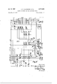
- Fig. 2 shows two incoming lines each with an operating bar and an operating magnet V1 and Vn, a cross-bar switch K1, a link m1 and part of a marker M1.
- Each incoming line FL has a glow discharge valve F1 and Fn respectively.
- Each primary cross-bar switch K1--K2 has two glow discharge valves FBI and R1, and FBZ and R2, respectively, in the marker M1.
- the glow discharge valve FA and the relays B, BA and P are common to all the primary selectors K1-K2.
- the relays MT1-MT20 for closing the circuits for the selecting magnets HAl, HBl, H11H10 are shown in Fig. 2.
- These relays have two contacts each, for example 52 and 54, for each primary cross-bar switch, for example K1, and each such contact pair indicates one link, for example m1.
- FIG. 3 the operating bar pertaining to the link ml in the cross-bar switch K21, the selecting magnets HA2, HBZ. H21H20 of said cross-bar switch, the outgoing line L1, and the rest of the marker M1 are shown.
- Means MM receive and register the signals from the incoming line, e. g. FL, connected to the marker.
- Relay Al connects those links M1, which are connected to the cross-bar switch K1, to a selecting means consisting of forty gas discharge valves TR1TR40, each with a pertaining relay T1T40.
- Relay G1 connects a group of relays W1- Wn to the registering means MM.
- Each one of the relays W1Wn corresponds to a traffic direction indicated by the registration in MM, and connects the outgoing lines, for example L1, comprised in the trafiic direction, which can be connected with one of the links for example m1, connected to the cross-bar switch K1, to the selecting means TR1-TR40, T1T40.
- the marker M2 forthe second group-selecting means in Fig. 1 is also indicated in Fig. 3.
- Each of the. gas discharge valves F1Fn and TR1 TR4-0 have several discharge paths connected in series in such a manner, that. the discharge path lying closest to for example the cathode must fire before the following, discharge path may be ionized and so on.
- the connecting means function according to the following description. Upon call on the line FL earth or zero voltage is connected to conductor c1. and an electrical current is obtained. over contact 11 through resistance r0, which is connected to a. positive voltage marked The voltage drop over resistance r0 ionizes the discharge path between the cathode 1 and the electrode 2 in valve F1, and an electrical current is obtained through resistance r1 in the marker M1. The voltage drop in resistance r1 lowers the voltage on the electrode 2 without extinguishing the valve R1 but enough to prevent other gas discharge valves, for example Fn, from firing. Should two gas discharge valves fire at the same time, one of them is extinguished, and therefore only one gas discharge valve F1Fn at a time can keep its discharge path 2 closest to the cathode ionized.
- the voltage drop in resistance r1 gives rise to a load current through condenser C1 and resistance 12 and a voltage drop in resistance r2, the gas discharge valve FA thereby firing between the auxiliary cathode 2 and the anode 3.
- the gas discharge valve FA thereafter also fires betweenthe anode 3 and the cathode 1 and then remains, ionized.
- Relay B attracts in the following circuit: contact m MM, Wire n2, Winding on relay B, gas discharge valve FA to earth. Contacts 21-23 are closed.
- Relay BA is energized over contact 21. Contacts 31-33 are closed. The following circuit is closed: the lower winding on relay G1, conductor g1,
- Each line FL is equipped with a selecting magnet, for example H11, and the cross-bar switch K1 comprises 10 operating bars and 12 selecting magnets.
- the voltage drop in resistance r5 causes a discharge current to flow through condenser C2 and resistance r4, the potential on the auxiliary anode 2 in the gas discharge valve R1 thereby increasing above I potential and the discharge path 2-1 firing and remaining ionized in a circuit from to earth through resistances r4 and r3 and over contact 41.
- Relay A1 closes circuits for all the free links, for example ml, which can be connected to the line FL over the cross-bar switch K1.
- the following circuit is closed for the link 1211: contacts 100, 131 and 132 respectively, resistance r11 and 212, respectively, the discharge path in the gas discharge valve TR1 or TR2 respectively lying closest to the cathode, to earth.
- the two gas discharge valves TR1 and TRZ fire, which indicates that one of the two lines in the called traffic route, for example L1 and L11, which are reached over link m1, is to be selected if free.
- the registering means MM operate relay Wu after all the signals required for the connection have been received from line FL. Simultaneously contact 140 is broken, relay B in Fig. 2 releases its armature, contacts 21-23 open and gas discharge valve FA is extinguished. Relay BA is kept energized over contacts 31 and 42 and relay G1 is kept energized over contacts 101 and 44 and conductor v2. Selecting magnet H11 releases its armature when contact 22 opens, but the discharge path 3-2 in the gas discharge valve F1 remains ionized with feeble current through resistance r7.
- a line for example L1
- Resistance r8 is common to all the gas discharge valves TR1-TR40 and is so great, that only one gas discharge valve at a time can ionize its third discharge path.
- the gas discharge valve TR1 fires its third discharge path, which indicates that line FL is to be connected to line L1 over link m1. According to the embodiment of the invention shown in Fig. 3 this takes place by a fourth discharge path, i. e.
- the glow discharge valve R1 is ionized with feeble current through the relatively high resistances r3 and r4.
- the following circuit is therefore closed: contact 52, conductor (12, the lower winding on operating magnet V2, conductor do, discharge path 3-1 in gas discharge valve R1, which now fires, the lower winding on selecting magnet H10, contact 54, winding on selecting magnet HA1, to negative.
- Selecting magnets HA1 and H10 and operating magnet V2 attract their armatures.
- Contact 16 and the contacts in the cross-bar switch K21 corresponding to selecting magnets HA2 and H20 and operating magnet V2 close.
- Contact 16 closes the following circuit: the upper winding on relay P, contact 16, the lower winding on operating magnet V1, discharge path 4-3 in gas dis charge valve F1, which now fires, discharge paths 3-2 and 2-1 in gas discharge valve F1, contact 11, conductor C1, to earth.
- Operating magnet V1 attracts its armature.
- Contacts 11-12 and the contacts in the cross-bar switch K1 corresponding to selecting magnets HA1 and H10 and operating magnet V1 are operated.
- Contact 11 extinguishes the gas discharge valve F1.
- Operating magnet V1 is kept energized over contact 12 by its upper winding.
- Operating magnet V2 is kept energized with current over contacts 201-202 and conductor 02.
- Line L1 is marked busy througha circuit over contacts 201, 202, 203 and 204 and conductors c2, and 03, contact thereby being actuated.
- Relay P attracts in series withthe lower winding on operating magnet V1 and contacts 41-44 are operated for a short while, during which relays Ba, G1, A1 and MT10 release. are extinguished. Relays Wu and T1 release and the gas discharge valve TR1 is extinguished. Holding circuits for the registering means MM not shown in the drawings are also broken, whereafter the marker is free for a new connection.
- a switchingstage comprising primary and secondary cross-bar switches, links connecting said primary and secondary cross-bar switches, a marker including registering means and selecting means, said selecting means comprising a plurality of gas discharge tubes, each of said tubes having a first electrode for a first discharge path, a second electrode for a second discharge path and a third electrode for a third discharge path, the said discharge paths being interconnected so that the first discharge path must be ionized before the second can be ionized and the second must be ionized before the third can be ionized, a calling line connected to one of said primary cross-bar switches and a called group of lines connected to said secondary crossbar switches, test conductors for each of said links and lines respectively connected in circuit with a source of current when the link or line is idle, a first connecting The gas discharge valves FBI and R1 means connecting said calling line to said marker, said registering means being settable by signals from the calling line to designate said called group, means identifying the primary cross-bar switch through which said calling line
- a fourth electrode connected in circuit with a source of current and forming a fourth discharge path in each of said discharge tubes ionized when the said first, second and third discharge paths all are ionized, a relay for each separate gas discharge tube connected in series with said fourth discharge path and operated when said fourth discharge path is ionized, and contacts on said relay for closing said closing circuits for the cross-bar switches.
- a switching stage comprises primary and secondary cross-bar switches, links connecting said primary and secondary cross-bar switches and at least two markers each including registering means and selecting means as defined in claim 1, the combination with a resistance for each of the lines in said called group of lines connected in series with said source of current and said test conductor and connected by said second connecting means to the second electrode in one of said discharge tubes in each of said markers, said resistance means preventing the second discharge path in the discharge tube of a line in one marker from being ionized simultaneously with the second discharge path in the discharge tube of the same line in another marker.
Description
Jan. 1957 A. c. JACOBAEUS ET AL 2,777,015
SELECTING MEANS WITH GAS DISCHARGE VALVE Filed May 12, 1953 s She'ts-Sheet 1 Fig.7
1957 A. c. JACOBAEUS ET A1. 2,777,015
SELECTING MEANS WITH GAS DISCHARGE VALVE Filed May 12, 1955 3 Sheets-Sheet 2 a WQ. 74
Jan. 8, 1957 A. c. JACOBAEUS ET AL 2,777,015
SELECTING MEANS WITH GAS DISCHARGE VALVE Filed May 12, 1955 3 Sheets-Sheet 5 ml K21 Ln L1 Fig. 3
firroR/ws y United States 2,777,015 Patented Jan. 8, 1957 SELECTING MEANS WITH GAS DISCHARGE VALVE Anton Christian Jacobaeus, Stockholm, and Arthur Berge, Hagersten, Sweden, assignors to Telet'onaktiebolaget L M Ericsson, Stockholm, Sweden, a corporation of Sweden Application May 12, 1953, Serial No. 354,498
Claims priority, application Sweden May 16, 1952 3 Claims. (Cl. 179-22) Such selecting means occur for example in telephone plants With cross-bar switches where the selecting means comprise one or two partial selection stages. A link between a first and a second partial selection stage cannot be selected in the first partial selection stage unless it can be connected with a free line pertaining to a called traffic route'over the other partial selection stage.
The object of the invention is to simplify the above dey scribed connecting process and to reduce the time for its execution. This is achieved by means of a selecting means consisting of at least onegas discharge valve for each of the lines of links within said group, said gas discharge valve comprising electrodes for at least three discharge paths, thefirst of said discharge paths having to fire before the second can be ionized and the second having to fire before the third can be ionized, means forionizing the first discharge path in the gas discharge valve when one ofsaid' second and third lines is free and for ionizing the second discharge path in the gas discharge valve if the remaining one of said two lines is free, an impedance connected in series witha source of potential to a common conductor interconnecting the'electrodes ofthe third discharge path, of all the gas discharge valves and which. is so great'that only one gas discharge valve at a time-can ionize said third discharge path, and means for each separate gas discharge valve, said means being operated when the thirddischarge path fires and causing the connection of. the calling line to the other line or connecting link.
The invention: will. be described more closely with referenceto. the accompanying drawings Figs. l-3.
Fig. 1 is, a. general diagram of two selecting meanswith primary cross-bar switches K1K 3 and secondary crossbar switches K11--K23.
, Fig, 2 is a circuit=diagramof the primary selection stage, and. Fig, 3. a.. circuit-diagram of the secondary selection, stagev and of said gas discharge valves TR1- IR40.
Fig;v 1. showst-wo. group-selecting means, one of which comprisesa number of primary. cross-bar switches K1- K2'and a number of secondary cross-bar switches K11 K22 as well as a, marker. M1. Only one primary crossbar switch. K3 and. two. secondary cross-bar switches K13,-K23 and the marker M2 inthe other group-selecting means. are. shown. Each operating bar in' the primary selectors can reach 20..links m1-m4 and each operating bar in the secondary selectors can reach 20 outgoing lines, part ofwhich at least L1L2, occurin both group-selecting means. An. incoming line FL connected to. an operating bar in thecross-bar switchf K1, is upon call on the line connected to the marker M1 over a C011? tact device k. The marker M1 is set by signals from the line FL, selects a free link, for example m1, and a free line, for example L1, and operates selecting bars and operating bars in the cross-bar switches K1 and K21 so that the line FL is connected to the line L1.
Fig. 2 shows two incoming lines each with an operating bar and an operating magnet V1 and Vn, a cross-bar switch K1, a link m1 and part of a marker M1. Each incoming line FL has a glow discharge valve F1 and Fn respectively. Each primary cross-bar switch K1--K2 has two glow discharge valves FBI and R1, and FBZ and R2, respectively, in the marker M1. The glow discharge valve FA and the relays B, BA and P are common to all the primary selectors K1-K2. Further, the relays MT1-MT20 for closing the circuits for the selecting magnets HAl, HBl, H11H10 are shown in Fig. 2. These relays have two contacts each, for example 52 and 54, for each primary cross-bar switch, for example K1, and each such contact pair indicates one link, for example m1.
In Fig. 3 the operating bar pertaining to the link ml in the cross-bar switch K21, the selecting magnets HA2, HBZ. H21H20 of said cross-bar switch, the outgoing line L1, and the rest of the marker M1 are shown. Means MM receive and register the signals from the incoming line, e. g. FL, connected to the marker. For each primary cross-bar switch K1K2 there are two relays, e. g. A1 and G1 or A2 and G2. Relay Al connects those links M1, which are connected to the cross-bar switch K1, to a selecting means consisting of forty gas discharge valves TR1TR40, each with a pertaining relay T1T40. Relay G1 connects a group of relays W1- Wn to the registering means MM. Each one of the relays W1Wn corresponds to a traffic direction indicated by the registration in MM, and connects the outgoing lines, for example L1, comprised in the trafiic direction, which can be connected with one of the links for example m1, connected to the cross-bar switch K1, to the selecting means TR1-TR40, T1T40.
The marker M2 forthe second group-selecting means in Fig. 1 is also indicated in Fig. 3.
Each of the. gas discharge valves F1Fn and TR1 TR4-0 have several discharge paths connected in series in such a manner, that. the discharge path lying closest to for example the cathode must fire before the following, discharge path may be ionized and so on. The discharge path between the anode and the electrode lying closest to the anodeca-nnot fi-re until all the other discharge paths are ionized.
The connecting means function according to the following description. Upon call on the line FL earth or zero voltage is connected to conductor c1. and an electrical current is obtained. over contact 11 through resistance r0, which is connected to a. positive voltage marked The voltage drop over resistance r0 ionizes the discharge path between the cathode 1 and the electrode 2 in valve F1, and an electrical current is obtained through resistance r1 in the marker M1. The voltage drop in resistance r1 lowers the voltage on the electrode 2 without extinguishing the valve R1 but enough to prevent other gas discharge valves, for example Fn, from firing. Should two gas discharge valves fire at the same time, one of them is extinguished, and therefore only one gas discharge valve F1Fn at a time can keep its discharge path 2 closest to the cathode ionized.
The voltage drop in resistance r1 gives rise to a load current through condenser C1 and resistance 12 and a voltage drop in resistance r2, the gas discharge valve FA thereby firing between the auxiliary cathode 2 and the anode 3. The gas discharge valve FA thereafter also fires betweenthe anode 3 and the cathode 1 and then remains, ionized. Relay B attracts in the following circuit: contact m MM, Wire n2, Winding on relay B, gas discharge valve FA to earth. Contacts 21-23 are closed. Relay BA is energized over contact 21. Contacts 31-33 are closed. The following circuit is closed: the lower winding on relay G1, conductor g1,
discharge path 3-2 in gas discharge valve F1, which is ionized when contact 32 closes, discharge path 2-1 in gas discharge valve F1, which according to the preceding is already ionized, contact 11 to earth over wire 01. Relay G1 and selecting magnet H11 attract their armatures. Contacts 101-104 are closed, and contacts 18-19 connect the talking wires a1 and 121 of the line FL to the conductors a and 120 in MG, which are connected to the signal-receiving relays in the registering means MM.
Each line FL is equipped with a selecting magnet, for example H11, and the cross-bar switch K1 comprises 10 operating bars and 12 selecting magnets.
When the discharge path 3-2 in the gas discharge valve F1 fires, a load current arises through condenser C3 and resistance r6. The voltage drop in resistance r6 ionizes the discharge path 3-2 in the gas discharge valve FBI, which causes the main path 3-1 in the gas discharge valve F81 also to fire and remain ionized in the following circuit: contacts 43 and 44, conductor v2, winding on relay A1, conductor s1, gas discharge valve FBI, resistance r to earth. Relay A1 actuates contacts 131-134.
The voltage drop in resistance r5 causes a discharge current to flow through condenser C2 and resistance r4, the potential on the auxiliary anode 2 in the gas discharge valve R1 thereby increasing above I potential and the discharge path 2-1 firing and remaining ionized in a circuit from to earth through resistances r4 and r3 and over contact 41.
Relay A1 closes circuits for all the free links, for example ml, which can be connected to the line FL over the cross-bar switch K1. The following circuit is closed for the link 1211: contacts 100, 131 and 132 respectively, resistance r11 and 212, respectively, the discharge path in the gas discharge valve TR1 or TR2 respectively lying closest to the cathode, to earth. The two gas discharge valves TR1 and TRZ fire, which indicates that one of the two lines in the called traffic route, for example L1 and L11, which are reached over link m1, is to be selected if free.
Suppose now that the registering means MM operate relay Wu after all the signals required for the connection have been received from line FL. Simultaneously contact 140 is broken, relay B in Fig. 2 releases its armature, contacts 21-23 open and gas discharge valve FA is extinguished. Relay BA is kept energized over contacts 31 and 42 and relay G1 is kept energized over contacts 101 and 44 and conductor v2. Selecting magnet H11 releases its armature when contact 22 opens, but the discharge path 3-2 in the gas discharge valve F1 remains ionized with feeble current through resistance r7.
When relay Wu attracts, contacts 111-116 are closed and the second discharge path in the gas discharge valves TR1-T1140 is ionized if the lines connected to the selecting means are free. The following circuit is closed for line L1: resistance r10, contacts 1.50 and 113, the two discharge paths in gas discharge valve TR1 lying closest to the cathode, to earth. The second discharge path in gas discharge valve TR1 fires, whereby resistance r is given such a great resistance, that the corresponding gas discharge valve TR1 in the second marker M2 cannot at the same time. Thereafter, the two discharge paths lying closest to the cathode in several of the valves TR1-TR40 can fire simultaneously and a line, for example L1, is chosen over the following circuit: contact 116, resistance r3, conductor wo, gas discharge valve TR1 to earth. Resistance r8 is common to all the gas discharge valves TR1-TR40 and is so great, that only one gas discharge valve at a time can ionize its third discharge path. Suppose now that the gas discharge valve TR1 fires its third discharge path, which indicates that line FL is to be connected to line L1 over link m1. According to the embodiment of the invention shown in Fig. 3 this takes place by a fourth discharge path, i. e. the path which lies between the anode and the auxiliary electrode, firing, and relay T1 attracting its armature in the following circuit: contact 43, conductor v1, contact 115, winding on relay T1, gas discharge valve TR1, to earth. Contacts 121 and 122 close. Relay MT10, which corresponds to link 1111 in the cross-bar switch K1, attracts in the following circuit: contact 44, conductor v2, contact 122, conductor :1, winding on relay MT10, to negative. Contacts 51-54 close. Simultaneously, selecting magnets HA2 and H20 in Fig. 3 attract with current over contacts 121 and 111 and select line L1 in the cross-bar switch K21.
According to the preceding the glow discharge valve R1 is ionized with feeble current through the relatively high resistances r3 and r4. The following circuit is therefore closed: contact 52, conductor (12, the lower winding on operating magnet V2, conductor do, discharge path 3-1 in gas discharge valve R1, which now fires, the lower winding on selecting magnet H10, contact 54, winding on selecting magnet HA1, to negative. Selecting magnets HA1 and H10 and operating magnet V2 attract their armatures. Contact 16 and the contacts in the cross-bar switch K21 corresponding to selecting magnets HA2 and H20 and operating magnet V2 close.
Relay P attracts in series withthe lower winding on operating magnet V1 and contacts 41-44 are operated for a short while, during which relays Ba, G1, A1 and MT10 release. are extinguished. Relays Wu and T1 release and the gas discharge valve TR1 is extinguished. Holding circuits for the registering means MM not shown in the drawings are also broken, whereafter the marker is free for a new connection.
There are time relays in the registering means MM, which release the marker if the connection cannot be completed. This takes place by operating relay P in a circuit over wire ul.
We claim:
1. In an automatic telephone system a switchingstage comprising primary and secondary cross-bar switches, links connecting said primary and secondary cross-bar switches, a marker including registering means and selecting means, said selecting means comprising a plurality of gas discharge tubes, each of said tubes having a first electrode for a first discharge path, a second electrode for a second discharge path and a third electrode for a third discharge path, the said discharge paths being interconnected so that the first discharge path must be ionized before the second can be ionized and the second must be ionized before the third can be ionized, a calling line connected to one of said primary cross-bar switches and a called group of lines connected to said secondary crossbar switches, test conductors for each of said links and lines respectively connected in circuit with a source of current when the link or line is idle, a first connecting The gas discharge valves FBI and R1 means connecting said calling line to said marker, said registering means being settable by signals from the calling line to designate said called group, means identifying the primary cross-bar switch through which said calling line is connected to the marker, a second connecting means operable by said registering means for connecting the test conductors for the lines in said called group to the second electrodes of said discharge tubes in said selecting means, a third connecting means connecting the test conductors for links over which said calling line is connectable to lines in said called group to the first electrodes in said discharge tubes in said selecting means, one link and one line which are connectable together over one of said secondary cross-bar switches being connected to the same discharge tube, an impedance means connected in series with a source of potential, a common conductorincluded in said series connection and interconnecting the third electrode of all said discharge'tubes whereby the first and the second discharge path in all discharge tubes connected to an idle link and an idle line areionized, said impedance means preventing the third discharge path in more than one of said discharge tubes from being ionized, means for each separate gas discharge tube operable in response to said third discharge path being ionized, and closing circuits for said cross-bar switches to connect said calling line to the idle line over the idle link connected to the discharge tube, all the three discharge paths of which are ionized.
2. In an automatic telephone system according to claim 30 1, a fourth electrode connected in circuit with a source of current and forming a fourth discharge path in each of said discharge tubes ionized when the said first, second and third discharge paths all are ionized, a relay for each separate gas discharge tube connected in series with said fourth discharge path and operated when said fourth discharge path is ionized, and contacts on said relay for closing said closing circuits for the cross-bar switches.
3. In an automatic telephone system of the kind wherein a switching stage comprises primary and secondary cross-bar switches, links connecting said primary and secondary cross-bar switches and at least two markers each including registering means and selecting means as defined in claim 1, the combination with a resistance for each of the lines in said called group of lines connected in series with said source of current and said test conductor and connected by said second connecting means to the second electrode in one of said discharge tubes in each of said markers, said resistance means preventing the second discharge path in the discharge tube of a line in one marker from being ionized simultaneously with the second discharge path in the discharge tube of the same line in another marker.
References Cited in the file of this patent UNITED STATES PATENTS Bruce et a1. Jan. 22, 1952-
Applications Claiming Priority (1)
| Application Number | Priority Date | Filing Date | Title |
|---|---|---|---|
| SE737509X | 1952-05-16 |
Publications (1)
| Publication Number | Publication Date |
|---|---|
| US2777015A true US2777015A (en) | 1957-01-08 |
Family
ID=20319744
Family Applications (1)
| Application Number | Title | Priority Date | Filing Date |
|---|---|---|---|
| US354498A Expired - Lifetime US2777015A (en) | 1952-05-16 | 1953-05-12 | Selecting means with gas discharge valve |
Country Status (5)
| Country | Link |
|---|---|
| US (1) | US2777015A (en) |
| BE (1) | BE519952A (en) |
| DE (1) | DE931291C (en) |
| FR (1) | FR1079359A (en) |
| GB (1) | GB737509A (en) |
Cited By (5)
| Publication number | Priority date | Publication date | Assignee | Title |
|---|---|---|---|---|
| US2911479A (en) * | 1955-10-19 | 1959-11-03 | Ericsson Telefon Ab L M | Control of selecting magnets in crossbar switches |
| US2925474A (en) * | 1956-06-14 | 1960-02-16 | Siemens Edison Swan Ltd | Automatic switching systems |
| US2970190A (en) * | 1958-01-15 | 1961-01-31 | Siemens Ag | Extending connection paths in a field of coupling points |
| US3049594A (en) * | 1955-07-12 | 1962-08-14 | Int Standard Electric Corp | Telephone systems |
| US3313888A (en) * | 1962-05-15 | 1967-04-11 | Hitachi Ltd | Split-switch crossbar trunking system |
Families Citing this family (1)
| Publication number | Priority date | Publication date | Assignee | Title |
|---|---|---|---|---|
| GB779235A (en) * | 1954-04-15 | 1957-07-17 | Automatic Telephone & Elect | Improvements in or relating to telephone systems |
Citations (3)
| Publication number | Priority date | Publication date | Assignee | Title |
|---|---|---|---|---|
| US2291040A (en) * | 1941-02-08 | 1942-07-28 | Bell Telephone Labor Inc | Switching system |
| US2326458A (en) * | 1942-02-17 | 1943-08-10 | Bell Telephone Labor Inc | Selection system |
| US2582959A (en) * | 1947-10-29 | 1952-01-22 | Bell Telephone Labor Inc | Electron-tube controlled switching system |
-
0
- BE BE519952D patent/BE519952A/xx unknown
-
1953
- 1953-05-12 US US354498A patent/US2777015A/en not_active Expired - Lifetime
- 1953-05-16 FR FR1079359D patent/FR1079359A/en not_active Expired
- 1953-05-16 DE DET7838A patent/DE931291C/en not_active Expired
- 1953-05-18 GB GB13911/53A patent/GB737509A/en not_active Expired
Patent Citations (3)
| Publication number | Priority date | Publication date | Assignee | Title |
|---|---|---|---|---|
| US2291040A (en) * | 1941-02-08 | 1942-07-28 | Bell Telephone Labor Inc | Switching system |
| US2326458A (en) * | 1942-02-17 | 1943-08-10 | Bell Telephone Labor Inc | Selection system |
| US2582959A (en) * | 1947-10-29 | 1952-01-22 | Bell Telephone Labor Inc | Electron-tube controlled switching system |
Cited By (5)
| Publication number | Priority date | Publication date | Assignee | Title |
|---|---|---|---|---|
| US3049594A (en) * | 1955-07-12 | 1962-08-14 | Int Standard Electric Corp | Telephone systems |
| US2911479A (en) * | 1955-10-19 | 1959-11-03 | Ericsson Telefon Ab L M | Control of selecting magnets in crossbar switches |
| US2925474A (en) * | 1956-06-14 | 1960-02-16 | Siemens Edison Swan Ltd | Automatic switching systems |
| US2970190A (en) * | 1958-01-15 | 1961-01-31 | Siemens Ag | Extending connection paths in a field of coupling points |
| US3313888A (en) * | 1962-05-15 | 1967-04-11 | Hitachi Ltd | Split-switch crossbar trunking system |
Also Published As
| Publication number | Publication date |
|---|---|
| DE931291C (en) | 1955-08-04 |
| FR1079359A (en) | 1954-11-29 |
| BE519952A (en) | |
| GB737509A (en) | 1955-09-28 |
Similar Documents
| Publication | Publication Date | Title |
|---|---|---|
| US2582959A (en) | Electron-tube controlled switching system | |
| US2204055A (en) | Telephone system | |
| US2354682A (en) | Electric selection controlling circuit | |
| US2777015A (en) | Selecting means with gas discharge valve | |
| US2261370A (en) | Telephone system | |
| US2691066A (en) | Automatic telephone system | |
| US2714630A (en) | Private automatic branch exchange | |
| US2913529A (en) | Automatic blocking of lines | |
| US2292371A (en) | Repeater circuit | |
| US2504274A (en) | System for automatic telephone exchanges with crossbar switches and private branch exchange trunk lines | |
| US2520130A (en) | Night switching for private automatic branch exchanges | |
| US2299203A (en) | Telephone system | |
| US2583848A (en) | Switching device for the setting of crossbar switches by means of markers | |
| US2275459A (en) | Telephone system | |
| US2299898A (en) | Telephone system | |
| US2302587A (en) | Telephone trunking system | |
| US2022030A (en) | Signaling system | |
| GB560732A (en) | Improvements in or relating to telephone or like systems employing crossbar switches | |
| US3548110A (en) | Selecting means | |
| US1719499A (en) | Telephone system | |
| US2815404A (en) | Connection for automatic ring signal | |
| GB536058A (en) | Improvements in telephone systems | |
| US3308245A (en) | Loop sensing circuit | |
| US1809039A (en) | Telephone exchange system | |
| US2347107A (en) | Switching system |