Sept. 11, 1956 J. B. MCGINN 2,762,514
STEEL SHIPPING PACKAGES FOR TRICOT SPOOLS Filed Sept. 16, 1952 3 Shees-Sheet 1 Sept. l1, 1956 B. MCG|NN 2,762,514
STEEL SHIPPING PACKAGES FOR TRICOT SPOOLS Filed Sept. 16, 1952 3 Sheets-Sheet 2 66 o 70 @9 4 62 f I9 79 7 l l n j 72 f 5f 7/ n 55a. 56
INVENTOR.
JAMES 'B. MCG/NN Arron y Y Sept. 11, 1956 J. B. MoGlNN 2,762,514
STEEL SHIPPING PACKAGES FOR TRICOT sPooLs Filed Sept. 16, 1952 3 Sheets-Sheet 5 7o f.f\, 68 68 7/ 6? I9 67 Q f4 al" Q 58 nl 72`d C ifa United Sttes Patent O STEEL SHIPPING PACKAGES FOR TRICOT SPOOLS James B. McGinn, Wyndmoor, Pa., assignor to American Viscose Corporation, Philadelphia, Pa., a corporation of Delaware Application September 16, 1952, Serial No. 309,785 8 Claims. (Cl. 211'13) This invention relates to the loading and transportation of yarn beams and the like. More particularly this invention concerns a shipping rack or support for a plurality of heavy spools or beams of yarn, which rack may be easily and safely loaded with the heavy beams of yarn and transported in a carrier or vehicle. With the use of this beam support rack, the usual damage incurred by the yarn stored on stacked beams through shifting of the load during transit is avoided. This application is a continuation in part of my copending application Serial No, 750,454, tiled May 26, 1947, which has now become abandoned.
The problem which gave rise to the present invention was the transportation of large spools of rayon yarn or the like from the manufacturing plant to the customers and converters. These spools or beams weight approximately 200 to 350 pounds each and in loading and transporting the spools considerable diiiiculty has been experienced in the past in arranging and supporting the spools in the truck or car body in a manner such as to -avoid shifting and resultant damage during transportation. Obviously, the question of space plays an important part in the problem and it became practically essential to load the spools in rows and in superimposed relation. Despite extreme care and more or less complicated reinforcing and chocking structures used in the loading, the losses resulting from shifting of the spools and crushing or bruising of a relatively large quantity of yarn carried by the spools or beams have been considerable. The damaged yarn is returned to the producer since it cannot be used by the converter.
The primary object of the present invention therefore is to provide an apparatus for securing relatively large heavy spools, beams or similar shaped objects in a manner such as to avoid shifting and resultant damage `to the contents of the spools during transportation.
Another object of the invention is to provide a rack or support which can be used to safely handle spools of thread such as rayon thread which is easily bruised or otherwise damaged.
Another object is to provide a rack or support for a plurality of relatively large and heavy spool-shaped objects or the like whereby the spools may Ibe loaded in superimposed relationship onto a truck or freight car body or other supporting structure expeditiously and with relative ease and transported any desired distance over rough roadways without danger of relative shifting and misalignment of the spools.
Other objects and advantages of the present invention willbecome apparent from a study of the following descript-ion and drawings wherein:
Figure l is a perspective of one embodiment rack or support of the present invention;
i Figure 2 is an enlarged View of detail A in Figure l;
Figure 3 is an elevation of another embodiment of the present invention wherein a modified beam clamp- ;ing apparatus is employed; and
of the Figure 4 is an enlarged, detail view showing the rais- Patented Sept. 11, 19.56
ing and lowering -means for the clamping members of the yarn beam support of Figure 3.
A preferred embodiment of the present invention is shown in Figures l and 2 of the drawing. As illustrated therein the supporting framework, rack or support 1 comprises the vertical members 2, 3, 4 and 5, the longitudinal members 6, 7 and the transverse members 8, 9, 10 and 11'. The structure is further strengthened by diagonal members or the like at the top and base of the framework. These members are all ysecured in place by welding or lthe like." As shown in Figure 1 of the drawing, the winding spools or beams are supported on their iianged ends on parallel transverse supports, or skid racks 12, 13, 14, 15, 16, 17, 18 and 19 which are secured to the vertical mem-bers, The skid racks are preferably constructed of ang-le iron and have spaced arcuate portions or beam receiving recesses B, B. The base portion of the racks acts as a supporting means for the vertical comp-onent of force of the winding spools, S, S and the vertical portion of the angle iron restricts the motion of the winding spools fin the longitudinal direction. Movable transverse parallel clamping members 26, 27, 28, 29, 30, 31, 32 and 33 are constructed in substantially the same manner as *the transverse skid racks. They are so placed so that their arcuate portions or beam receiving recesses C, C are directly above the arcuate portions B, B of the opposite skid racks. The clamping members act to restrict movement of the beams S, S in a longitudinal and vertical direction. With beams lying in place in the arcuate portions C, C and B, B of the clamping means and skid racks, movement in a transverse direction is restricted, The vertical members 20, 21, 22, 23, 24 and 25 are secured to the vertical section of the transverse skids such as by welding or the like. However the vertica-l members 21 and 24 are slotted in the same manner as the vertical members 2, 3, 4 and 5 to add stability to the movable transverse parallel clamping members 26, 27, 28, 29, 30, 31, 32 and 33. These vertical members act to strengthen the supporting framework yand also to prevent any longitudinal movement of the beams within the framework 1.
In loading the beams or spools, S, S, the transverse arcuate flanged clamping members 26-33 are raised to allow suiiicient space for the beams to be inserted in place within the bea-m supporting recesses B, B. The mechanism by which the movement of the clamping members is accomplished is better shown in Figure 2. Reference character 30 indicates one of the transverse arcuate clamping means employed in the present invention. Secured t-o the upper edge of the clamping means 30 is a bearing plate 34 having a bore 35 which is countersunk at each end to form shoulders 36 and 37 on opposite sides of said bore. The shoulders 36 and 37 for-ma bearing surface for the retaining knobs 38 and 39 which are secured by pins or the like at spaced portions near one end of the locking screw 40. The opposite end of the shaft has a socket connection 41 which fits any standard size socket wrench. The locking screw 40 is lsupported by an internally threaded bracket 43 pivotally mounted at 43 on the vertical member 2. i
A threaded stud 44 is secured to each end of the transverse clamping means 30. The studs 44 are slidablev in slots 45 in the vertical members 2, 3, 4 and 5 and are 'held in a predetermined posi-tion by the locking nuts 46 that screw on the threaded end of the studs 44. When the locking screw is turned counterclockwise the trans` verse clamping member 30 rises, guided by the studv 44 in the slot 4S. When these transverse clamping members are so raised, they give easy access to load or unload the beams. Each of the transverse clamping members has one locking screw that raises or lowers said clamp'- ing means to any desired position. The main con-sidera- 3 tion in varying the size of the supporting framework 1 is that there be the same number of locking screws as there are clamping members.
The beams S, S are loaded by placing them Von the skid racks in the spaced arcuate `portions or beam recesses B, B provided thereon and the locking screw is turned in a clockwise direction until the arcuate portions C, C of the Vclamping members Contact the beams S, S. When the desired relationship between the beams and the .clamping means is attained, the lock nuts on the studs are tightened to secure the clamping members in that position.
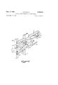
Asecond embodiment of the present invention is shown inFigures 3 and yl of the drawing. AAs illustrated therein, the supporting frame or support Sl is preferably substantially similar to the frame of the previously described embodiment and includes the fixed transverse skid racks 52 which provide a suitable base or supportfor the various spools or beams S, S and the adjustable clamping members 54 which are adapted to prevent and `restrain relative movement of the beams. The slots 55a in the vertical or upright members S of the frame are preferably vertically 4disposed as shown and cooperate with the studs or the like 55 adjacent the opposite extremities of the clamping members to guide the same during the beam clamping and unclarnping operations. As in the previously described embodiment, one extremity of each of thestuds or the like 56 is preferably threaded to receive the locking nut or the like 56a. The plate members 57 which are secured to and extend upwardly from the clamping members adjacent the spaced arcuate portions C, C thereof are diagonally slotted as at 58 and as will vbe more apparent hereinafter are adapted to cooperate withapparatus which determines and controls the vertical position of each of the clamping members in the slots 55a of the upright members. Similarly the members 59 with their beveled Yupper surfaces 59a are also secured to and extend upwardly from the clamping members .and as will be more apparent hereinafter are Vadapted .to facilitate movement of the same during the clamping .and unclamping operation.
The elongated shaft 60 which isV preferably Ypositioned above and substantially parallel to each of the clamping members 54 is journaled in the bearings or eye members '61, 62 and 63 which are secured to theframe 51 in any suitable manner. The collar members or the like 64 are secured to the shaft preferably on each :side Vof the eye member 62 bythe setscrews 65 as shown and thereby prevent the longitudinal movement of the shaft.
vThe shaft which is oppositely threaded adjacent its extremities at 66 and 67 is adapted to cooperate with the complementary threads of the cam members or the'like 68`so that on rotation of the shaft the cam members slide toward or away from one another in a grooved portion 69 of the guide members 70 which are mounted on the frame in any suitable manner. The studs or the like 71 which are preferably secured to a lower portion of each cam `member 68 cooperate with the associated slotted portions of the plate members 57 and therefore cause the clamping members to move in the slots 58m response to the rotation of the shaft 60. Thus as theshaft isrotated by .a tcrank or the rlike which cooperates with the polygonalextremity 72 of the shaft and as the cam members 681move -along the grooved portions of theguide members 70 the cam member studsslide in the slottedportions of the plate member 57v and raise or lower vthe clamping membersin the slots :55a between the clamping and -unclampingpositions. The beveled membersr59 are adapted to cooperate with the complementary beveledV lower surface '68 of the cam member 68 during the clamping and .unclamping operation to facilitate the same.
While Y preferred :embodiments of the invention have been disclosed, the description is intended to be illustrative only and itis to be understood that changes 'and variationssmay be made without departing from the jspirit and ,scope ofthe invention as deiinedby'the present-clairns.
I claim:
l. A supporting device for wound beams comprising a framework having vertical members disposed Within two substantially parallel planes, a pair of fixed transverse members disposed in a horizontal plane each having a plurality of longitudinally spaced beam receiving recesses, one of the fixed transverse members being secured to the vertical'members in one plane and the other being secured to the vertical members in the other plane, a pair of movable transverse ymembers each having -a Iplurality of longitudinally spaced beam receiving'recesses andxeach movable member being supported movably Within 'the framework above and substantially parallel to one .of .the fixed members, each recess of a movable member having its concavity facing the 'concavity of `a recess of the corresponding lixed transverse members spaced immediately below, and means for moving the movable members toward and away from the corresponding fixed members, said moving means being connected with a movable member .to move all portions thereof substantially equal distances with respect to the opposed portions of the corresponding fixed members.
2. A supporting device for wound beams comprising a supporting framework including a rectangular base ,portion having vertical members at each corner, a pair of fixed parallel transverse supports disposed in a horizontal plane each'having a plurality of longitudinally spaced arcuate sections and being secured to a separate pair ,of the vertical members, a pair of transverse members relatively movable witb respect to the vertical members and each having a plurality of longitudinally spaced arcuate sections and being supported movably within the framework above and substantially parallel to one of ythe fixed supports by means of parallel slots inclined to thehorizontal in at least one of the members and laterallyrproiecting elements xed to at least another of the transverse members with respect to which said one is relatively movable, each arcuate section of each movable member having its concave surface facing the concave surface of an arcuate section of the corresponding lixed transverse support spaced immediately below, and means connected to the 4movable members and the framework adjacent one end of the framework for moving the movable members toward and away from the corresponding :fixed supports.
3. A supporting device for spool-'shapedarticles comprising a supporting framework including a rectangular base portion having vertical'mernbers at each corner, a plurality of superimposed pairs of xed transverse members disposed in Ihorizontal planes, each fixed transverse member having a plurality of longitudinally spaced Vconcave surfaces and the concave surfaces of all 'of the fixed members facing in the same direction, one 'member vof each pair of fixed transverse members being secured to Ya plurality of the vertical members on oneside ofthe framework and the other transversemember of each pair being secured to a plurality 'of the vertical members on the other side of the framework, a plurality ofmovable transverse members equal in number to the vxed members,
each of -said movable members having longitudinal spaced 'concave surfaces opposed to the concave Ysurfaces of its corresponding fixed member, vmeans for movably supporting each movable member in'horizontal and substantially parallel disposition above a fixed member, said means comprising a plurality of parallel slots extending at an inclination to the horizontal within the framework ladjacent each movable member, laterally extending ele- -ments ixedly secured to the movable'member andy extending into said slots, and screw Vmeans connected to the movable lmember Vand a portion of the framework for raising and lowering the movable member underthe control of said elements and slots.
4. lAsupporting device for -wound beams: comprisingal substantially rectangular base, upright members Ysecured to each corner of the base, a'pair of horizontally disposed parallel support members having longitudinally spaced beam receiving recesses, each support member being secured to and extending between a pair of adjoining upright members, a pair of horizontally disposed movable clamping members having longitudinally spaced beam receiving recesses and being positioned vertically above and substantially parallel to the fixed support members, vertical slots in the upright member, means projecting from the clamping members which cooperate with the vertical slots in the upright members to guide their movement toward and away from the fixed support members, an elongated shaft mounted on the upright members substantially parallel to each of the clamping members, said shaft having oppositely threaded portions adjacent its opposite extremities; and means which cooperate with the oppositely threaded portions of the shaft and with the associated clamping member to adjust its position in the slots in the upright members.
5. A supporting device for wound beams comprising a substantially rectangular base, upright members secured to each corner of the base, a pair of horizontally disposed parallel support members having longitudinally spaced arcuate portions, each support member being secured to and extending between a pair of adjoining upright members, a pair of horizontally disposed movable clamping members having longitudinally spaced arcuate portions and being positioned vertically above and substantially parallel to the fixed support members, slots in the upright members, means projecting from the clamping members which cooperate with the slots in the upright members to guide their movement toward and away from the fixed support members, an elongated shaft mounted on the uprights members substantially parallel to each of the clamping members, said shaft having oppositely threaded portions adjacent its opposite extremities, plate members having diagonally slotted portions formed therein secured to and extending upwardly from each of the clamping members, and cam means which cooperate with the oppositely threaded portions of the shaft and with the slotted plate members to adjust the position of each of the clamping members in the slots in the upright members.
6. A supporting device for wound beams comprising a substantially rectangular base, upright members secured to each corner of the base, a pair of horizontally disposed parallel support members having longitudinally spaced arcuate portions, each support member being secured to and extend-ing between a pair of adjoining upright members, a pair of horizontally disposed movable clamping members having longitudinally spaced arcuate portions and being positioned vertically above and substantially parallel to the fixed support members, slots in the upright members, means projecting from the clamping members which cooperate with the slots in the upright members to guide their movement toward and away from the fixed support members, an elongated shaft mounted on the upright members substantially parallel to each of the clamping members, said shaft having oppositely threaded portions adjacent its opposite extremities, plate members having diagonally slotted portions formed therein secured to and extending upwardly from each of the clamping members, cam means which cooperate with the oppositely threaded portions of the shaft and with the slotted plate members to adjust the position of each of the clamping members in the slots in the upright members, the lower surfaces of the cam means having beveled lower surfaces, and members which have beveled upper surfaces and which are secured to and extend upwardly from the clamping members to engage the beveled lower surfaces of the cam means.
7. A supporting device for wound beams according to claim 1 wherein the beam receiving recesses comprise arcuate sections.
8. A supporting device for wound beams according to claim 4 wherein the beam receiving recesses comprise arcuate portions.
References Cited in the file of this patent UNITED STATES PATENTS 166,512 Dolph et al Aug. 10, 1875 840,696 Heberling Jan. 8, 1907 1,220,450 Pavey et al Mar. 27, 1917 1,298,578 Schneider Mar. 25, 1919 1,453,474 Mauran May 1, 1923 1,631,304 Willoughby June 7, 1927 1,791,336 Warshaw Feb. 3, 1931 2,024,411 Willoughby Dec. 17, 1935 2,144,600 Koonee Ian. 17, 1939 2,288,622 Heigis July 7, 1942 2,422,768 Benn June 24, 1947