US273673A - Theodore m - Google Patents
Theodore m Download PDFInfo
- Publication number
- US273673A US273673A US273673DA US273673A US 273673 A US273673 A US 273673A US 273673D A US273673D A US 273673DA US 273673 A US273673 A US 273673A
- Authority
- US
- United States
- Prior art keywords
- beams
- arm
- shovel
- sleeve
- spring
- Prior art date
- Legal status (The legal status is an assumption and is not a legal conclusion. Google has not performed a legal analysis and makes no representation as to the accuracy of the status listed.)
- Expired - Lifetime
Links
- 210000005069 ears Anatomy 0.000 description 3
- 229940000425 combination drug Drugs 0.000 description 1
- 238000010276 construction Methods 0.000 description 1
- 230000003028 elevating effect Effects 0.000 description 1
- 230000003245 working effect Effects 0.000 description 1
Images


Classifications
-
- A—HUMAN NECESSITIES
- A01—AGRICULTURE; FORESTRY; ANIMAL HUSBANDRY; HUNTING; TRAPPING; FISHING
- A01B—SOIL WORKING IN AGRICULTURE OR FORESTRY; PARTS, DETAILS, OR ACCESSORIES OF AGRICULTURAL MACHINES OR IMPLEMENTS, IN GENERAL
- A01B35/00—Other machines for working soil not specially adapted for working soil on which crops are growing
- A01B35/02—Other machines for working soil not specially adapted for working soil on which crops are growing with non-rotating tools
- A01B35/04—Other machines for working soil not specially adapted for working soil on which crops are growing with non-rotating tools drawn by animal or tractor or man-power
- A01B35/08—Other machines for working soil not specially adapted for working soil on which crops are growing with non-rotating tools drawn by animal or tractor or man-power with rigid tools
Definitions
- FIG 3 Patented Mar. 6,1883;
- This invention relates to that class of cultivators known as straddle-row walking cultivators.
- the object of this invention is to produce a cnl tivatorcapableofbeinghandled with greater ease and certainty, to enable the operator to produce better results; and it consistsin mech- 1 anism capable of adjustment to cause the cultiva-tor-teeth to engage the ground with greater or less force; in mechanism to assistin elevating the shovel-beams; in mechanism to hold the shovel-beams elevated in turning and gettinginto position to employ the cultivator, and from which position they may be lowered to their working position by a downward pull on the handles, and in mechanism to suspend the shovel-beams for the purposes of transportation.
- Figure l is a side elevation of a cultivator embodying my invention, and in which the outer carryingwheel is omitted, and the shovel-beams are represented in their working position.
- Fig. 2 is a side elevation of a cultivator embodying my invention, and in which the outer carryingwheel is omitted, and the shovel-beams are represented in their working position.
- Fig. 2 is a side elevation of a cultivator embodying my invention, and in which the outer carryingwheel is omitted, and the shovel-beams are represented in their working position.
- At B are represented carrying wheels, mounted to revolve on the axle-arms of the bent axle-tree.
- At (l are represented tongue-beams, having their rear end portions fixed to the vertical arms of the axle-tree in the inner angle formed by the vertical arms and central horizontal portion thereof.
- These beams from their connection with the axle-tree, extend forward, inclining toward each other, and meet at a proper 6o distance in front of the axle-tree; and their meeting ends are fitted to receive the neckyoke to connect with the harness of the team.
- a is represented a metallic semi-sleeve, semicircular in cross-section, and of suitable dimensions and conformation to receive the outside and upper curving end portion of the vertical arms of the bent axle-tree.
- These sleeves near their upper ends, are provided with an ear, 0, projecting in thelengthwise direction of the tongue-beams, and are perforated to receive the screw-threaded arms of the staple-bolts d, which extend through the tonguebeams, and by means of screw-nuts serve to fix the parts firmly together.
- the sleeves, at the point Which receives the loop or how portion of the screWstaples, are formed with a groove, producing a seat to receive them.
- the ears 0 of the sleeves are provided with an additional hole to receive an additional bolt to connect it with the tongue-beams to give additional firmness and strength to the parts.
- At D are represented tubular collars fitted to receive the outer portion of the axle-tree, immediately inside of the carrying-wheels. These collars are provided with perforated ears 8, projecting from their forward side, and receive the lower hook end, 71, of the bracerods E. These brace-rods Eextend from their connection with the ears e to meet the tonguebeams forward of the axle-tree, at which point they are fixed to the beams by suitable screwbolts.
- At F are represented sleeves placed upon the lower horizontal portion of the axle-tree, between the vertical arms thereof a nd the tubular collars D. These sleeves F are provided I00 rial,having their rear ends curved downward.
- shovels or cultivatorteeth suitably connected to the downturned rear ends of the beams by safety attachments, and are made vertically adjustable, and capabio of being turned with their face oblique to the line of travel to throw the earth to either side.
- handles fixed to the beams by means of which the operator can control the movements of the cultivator-shovels.
- the inner ends of the sleeves F are provided with an uprising lateral arm, m, which rises on the outside of the vertical arms of the axle-tree, and are also provided with an arm, n, depending from its extreme inner end, and thesev depending arms are provided with a series of holes, 0, variously distributed, the purpose of which, in connection with the depending arm n and the lateral arm at, will be hereinafter described.
- curved levers of the form shown one of which is employed on each side of the machine, having their fulcrum-support on the tubular stud p of the semi-sleeve a.
- the lower ends of the depending arms of these curved levers are fitted with a traveling roller, s, inposition to engage the rear side of the lateral arm m, and their upper arms are curved rearward, having their extreme rear ends produced in hook form, adapted to receive the shovel-beams, when elevated, to hold them suspended for the purpose of transportation.
- At t is represented a spring having a rod or bar extension at each end.
- the end of one of these extensions is produced in book form,
- the upper extension rods or bars of the spring 1? are screw-threaded, and extend upward through an ear,u, proj ectingfrom the upper portion of the curved levers K, and their screw-threaded ends are provided with a thumb-nut, by means of which the tension of the spring may be varied to give the required force to support the shovel-beams properly.
- the metallic semi-sleeves a are provided with a curved transverse bar, 22, extending forward and rearward thereof, and serves as a guide to the movements of the curved lever.
- the line of spring action will be forward of the axial center, on which the beams vibrate vertically, and in such relation to the point of contact of the traveler with the lateral arm of the sleeve to which the shovel-beams are connected that the spring action will operate to hold the shovels to the ground at their working depth with greater force and firmness, and cause them to run at a uniform depth, and when the ground is very hard this feature is of great value.
- the spring is connected to the depending arm in the rear lower hole and the shovelheams are in their working position,as atFi g.
- the spring action will be slightly forward of the axial center on which the beams vibrate vertically, and in such relation to the pointof contact of the traveler with the lateral arm of the sleeve to which the -95 1, the line of spring action wlll be rearward of shovel-beams are connected that these two forces will be substantially in equilibrium, and will not materially change the working action of the cnltivators.
- the holding force of the spring can be varied by means of the thumb-screw on its upper end, to hold the beams suspended in the same position as shown in Fig. 6, and to be lowered therefrom in the same manner.
- the shovelbeams are raised to engage the hook on the rear end of the lever, as represented in Fig. 2.
- the spring in its connection with the depending arm of the sleeve to which the shovel-beams are pivoted and its position relatively with the several parts with which it coacts, may be varied to any practical extent and still be within the scope of myinvention.
- l have also described the guide to the movements of the curved lever as consisting in a curved bar fixed to the semi-sleeve, and the stop to limit its rearward movements as a projection on its rear end; but evidently these parts may be independent, and are capable of various constructions to accomplish the same results without departing from the gist of this part of my invention.
- Aspring substantially as herein described, havingasuitable connection with the dependin g arm of the sleeve to which the shovelbeams are pivoted, and an adjustable connection with the free arm of the lever which engages the lateral uprising arm of the sleeve for the purpose of varying its spring force, substantially as and for the purpose hereinbefore set forth.
- the pivoted lever having a depending arm for engaging the uprising lateral arm of the sleeve, in combination with a stop for limiting the throw of said lever, substantially as and for the purpose set forth.
Landscapes
- Life Sciences & Earth Sciences (AREA)
- Zoology (AREA)
- Engineering & Computer Science (AREA)
- Mechanical Engineering (AREA)
- Soil Sciences (AREA)
- Environmental Sciences (AREA)
- Soil Working Implements (AREA)
Description
2 Sheets-Sheet 1.
(No Model.)
T. M. PLENNIKEN, Decd.; W. MGGREGOR, Administrator. GULTIVATOR. Ne. 273,673. Patented Mar.6,1883.
in. A
ATTESTI (No Model.) 2 Sheets-Sheet 2.
- T. M. FLENNIKENJDeod.
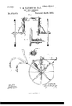
W. MGGREGOR, Administrator. GULTIVATOR. N0.'273,673. FIG 3 Patented Mar. 6,1883;
5 2 E M a 1 P1 E. E5.
dr- 1 L h ATTEST: J/INVENTUR.
BY aa ATTY.
TATES ATENT ICEQ THEODORE M. FLENNIKEN, OF ROCKFORD, ILLINOIS, (YVILLIAM MCGREGOR ADMINISTRATOR OF SAID FLENNIKEN, DEOEASED;) SAID FLENNIKEN ASSIGNOR TO NORMAN O. THOMPSON, OF SAME PLACE.
CULTlVATOR.
SPECIFICATION forming part of Letters Patent No. 273,673, dated March 6, 1883.
Application filed February 27, 1882. (N model.)
To all whom it may concern:
Be it known that I, THEODORE M. FLENNI- KEN, a citizen of the United States, residing in the city of Rockford, in the county of Winnebago and State of Illinois, have invented new and useful Improvements in Cultivators, of which the following is a specification.
This invention relates to that class of cultivators known as straddle-row walking cultivators.
The object of this invention is to produce a cnl tivatorcapableofbeinghandled with greater ease and certainty, to enable the operator to produce better results; and it consistsin mech- 1 anism capable of adjustment to cause the cultiva-tor-teeth to engage the ground with greater or less force; in mechanism to assistin elevating the shovel-beams; in mechanism to hold the shovel-beams elevated in turning and gettinginto position to employ the cultivator, and from which position they may be lowered to their working position by a downward pull on the handles, and in mechanism to suspend the shovel-beams for the purposes of transportation. These and other features, including the necessary devices and their several com binations, all ofwhich will be hereinafter more fully described, constitute the subjcct'matter of this specification.
In the accompanying drawings, Figure l is a side elevation of a cultivator embodying my invention, and in which the outer carryingwheel is omitted, and the shovel-beams are represented in their working position. Fig. 2
is also a side elevation with outer carrying.- wheel omitted, and in which the'shovel-beams are represented in position for transportation. Fig.3 is a. rear elevation in which the shovelbeams are omitted. Fig. 4 is a central verti- 0 cal section of a portion of bent axle-tree and shovel'beam connection on dotted line 00. Fig. 5 is a transverse section on dotted line 9 and Fig. 6 is an inside elevation of one side of the cultivator with shovel-beams suspended in 4 5 their elevated position for turning and getting into position to employ the cultivator.
In the figures, A represents a bent or crankformed axle-tree, having its axle-arm portions fitted to receive carrying-wheels to revolve 5o thereon.
At B are represented carrying wheels, mounted to revolve on the axle-arms of the bent axle-tree.
At (l are represented tongue-beams, having their rear end portions fixed to the vertical arms of the axle-tree in the inner angle formed by the vertical arms and central horizontal portion thereof. These beams, from their connection with the axle-tree, extend forward, inclining toward each other, and meet at a proper 6o distance in front of the axle-tree; and their meeting ends are fitted to receive the neckyoke to connect with the harness of the team.
These parts are substantially the same as like parts of similar machines now in use, and to be found in the trade.
At a is represented a metallic semi-sleeve, semicircular in cross-section, and of suitable dimensions and conformation to receive the outside and upper curving end portion of the vertical arms of the bent axle-tree. These sleeves, near their upper ends, are provided with an ear, 0, projecting in thelengthwise direction of the tongue-beams, and are perforated to receive the screw-threaded arms of the staple-bolts d, which extend through the tonguebeams, and by means of screw-nuts serve to fix the parts firmly together. The sleeves, at the point Which receives the loop or how portion of the screWstaples, are formed with a groove, producing a seat to receive them. The ears 0 of the sleeves are provided with an additional hole to receive an additional bolt to connect it with the tongue-beams to give additional firmness and strength to the parts. 8
At D are represented tubular collars fitted to receive the outer portion of the axle-tree, immediately inside of the carrying-wheels. These collars are provided with perforated ears 8, projecting from their forward side, and receive the lower hook end, 71, of the bracerods E. These brace-rods Eextend from their connection with the ears e to meet the tonguebeams forward of the axle-tree, at which point they are fixed to the beams by suitable screwbolts.
At F are represented sleeves placed upon the lower horizontal portion of the axle-tree, between the vertical arms thereof a nd the tubular collars D. These sleeves F are provided I00 rial,having their rear ends curved downward.
At H are represented shovels or cultivatorteeth, suitably connected to the downturned rear ends of the beams by safety attachments, and are made vertically adjustable, and capabio of being turned with their face oblique to the line of travel to throw the earth to either side.
At I are represented handles fixed to the beams, by means of which the operator can control the movements of the cultivator-shovels. The inner ends of the sleeves F are provided with an uprising lateral arm, m, which rises on the outside of the vertical arms of the axle-tree, and are also provided with an arm, n, depending from its extreme inner end, and thesev depending arms are provided with a series of holes, 0, variously distributed, the purpose of which, in connection with the depending arm n and the lateral arm at, will be hereinafter described. The semi-sleeves a are provided near their lower-ends with a tubular stud, p, projecting laterally outward, and at this point the sleeves are enlarged and adapted to receive a screw-eyebolt, r, fitted to receive the vertical arm of the axle-tree, and its screw-threaded arm extends outward through the tubular stud, having its projecting screwthreaded end provided with a washer and with a screw-nut, by means of which the parts are securely clamped and held in position.
At K are represented curved levers of the form shown, one of which is employed on each side of the machine, having their fulcrum-support on the tubular stud p of the semi-sleeve a. The lower ends of the depending arms of these curved levers are fitted with a traveling roller, s, inposition to engage the rear side of the lateral arm m, and their upper arms are curved rearward, having their extreme rear ends produced in hook form, adapted to receive the shovel-beams, when elevated, to hold them suspended for the purpose of transportation.
At t is represented a spring having a rod or bar extension at each end. The end of one of these extensions is produced in book form,
adapted to enter the holes 0 in the depending arm n of the sleeves F in such a manner as to be readily changed to any of the holes in the depending arm. The upper extension rods or bars of the spring 1? are screw-threaded, and extend upward through an ear,u, proj ectingfrom the upper portion of the curved levers K, and their screw-threaded ends are provided with a thumb-nut, by means of which the tension of the spring may be varied to give the required force to support the shovel-beams properly. The metallic semi-sleeves a are provided with a curved transverse bar, 22, extending forward and rearward thereof, and serves as a guide to the movements of the curved lever. The rear extensions of these bars are formed with an outward projection, w, which serves to limit the rearward movements of the levers. In this instance the holes 0 in thedepending arm n of the sleeve F are arranged in such a manner that when the spring is connected in the forward lower hole and the shovel-beams are in their working position, as at Fig. 1, the line of spring action will be forward of the axial center, on which the beams vibrate vertically, and in such relation to the point of contact of the traveler with the lateral arm of the sleeve to which the shovel-beams are connected that the spring action will operate to hold the shovels to the ground at their working depth with greater force and firmness, and cause them to run at a uniform depth, and when the ground is very hard this feature is of great value. When the spring is connected to the depending arm in the rear lower hole and the shovelheams are in their working position,as atFi g.
the axial center on which the beams vibrate vertically, and in such relation to the point of contactof the traveler with the lateral arm of the sleeve to which the shovel-beams are connected that the spring action will operate to counteract the downward tendency of the "shovel-beams and cause them to adhere to the ground with less force. This feature,when the ground is light, is found to be valuable, and greatly relieves the operator. If the spring is connected in the center or upper hole in the depending arm and the shovel-beams are in their working posit-ion, the spring action will be slightly forward of the axial center on which the beams vibrate vertically, and in such relation to the pointof contact of the traveler with the lateral arm of the sleeve to which the -95 1, the line of spring action wlll be rearward of shovel-beams are connected that these two forces will be substantially in equilibrium, and will not materially change the working action of the cnltivators. It will be seen, however, that inany of the positions of the spring, in connection with the depending arm hereinbefore described, when the shovel-beams are raised the action of the spring will cause the traveler in the lower end of the curved lever to ascend the lateral arm until the lever engages the outward-projecting stop to on the curved guide-bar '0, when the relative position of its lower arm with the lateral arm, in connection with-the spring action,will be such as to hold the beams suspended, as represented in Fig. 6, to lessen the labor in handling, as in turning at the ends of the rows, or in getting the machine in position to be employed in cultivation, and when in position the beams can be lowered to their working position by a downward pull on the handles. When the hook end of the lower spring-bar is connected to the depending arm, in either of the holes therein, the holding force of the spring can be varied by means of the thumb-screw on its upper end, to hold the beams suspended in the same position as shown in Fig. 6, and to be lowered therefrom in the same manner.
For the purpose of transportation the shovelbeams are raised to engage the hook on the rear end of the lever, as represented in Fig. 2. It will readily be seen that the spring, in its connection with the depending arm of the sleeve to which the shovel-beams are pivoted and its position relatively with the several parts with which it coacts, may be varied to any practical extent and still be within the scope of myinvention. l have also described the guide to the movements of the curved lever as consisting in a curved bar fixed to the semi-sleeve, and the stop to limit its rearward movements as a projection on its rear end; but evidently these parts may be independent, and are capable of various constructions to accomplish the same results without departing from the gist of this part of my invention.
In the foregoing I have omitted some parts necessary to produce a complete machine; but such omitted parts may be supplied by the employment ofanyof the known or usual parts capable of use in connection with my improved machine.
I claim as my invention 1. The combination, with the sleeve to which the shovel-beams are pivoted,'provided at its inner end with an uprising lateral arm, of a lever pivoted to the main frame or axle and adapted to engage the uprising lateral arm,
but disconnected therefrom, substantially as and for the purpose set forth.
2. The sleeve to which the shovel-beams are pivoted, provided with an uprising arm and a depending arm, and a pivoted lever, one end of which is adapted to engage the lateral arm, but disconnected therefrom, in combination with the spring connected to the free end of the pivoted lever and with the depending arm of the sleeve, substantially as and for the purpose set forth.
3.Aspring,substantially as herein described, having an adjustable connection with the depending arm of the sleeve to which the shovelbeams are pivoted, and a suitable connection with the free arm of the lever which engages the lateral uprising arm of the sleeve, for the purpose of varying its action on the shovelbeams, substantially as hereinbet'ore set forth.
4. Aspring, substantially as herein described, havingasuitable connection with the dependin g arm of the sleeve to which the shovelbeams are pivoted, and an adjustable connection with the free arm of the lever which engages the lateral uprising arm of the sleeve for the purpose of varying its spring force, substantially as and for the purpose hereinbefore set forth.
5. The combination, with the pivoted lever having a depending arm for engaging the uprising lateral arm of the sleeve to which the shovel-beams are connected, of a guideway, 21, for engaging the free arm of said lever for directing the vibratory movement of the same, substantially as and for the purpose hereinbefore set forth.
6. The pivoted lever having a depending arm for engaging the uprising lateral arm of the sleeve, in combination with a stop for limiting the throw of said lever, substantially as and for the purpose set forth.
7. The combination, with the pivoted lever for automatically controlling the movements of the shovel-beams, ofa guide bar or way to direct the movements of said lever, and a stop to limit its rearward movement, substantially as described.
8. The combination, with the sleeve to which the shovel-beams are pivoted, provided with an uprising lateral arm, of a pivoted lever, one end of which is adapted to engage the lateral arm of the sleeve, and having a free hooked end to engage the shovel-beams, substantially as and for the purpose set forth.
THEODORE M. FLENNIKEN.
Witnesses:
O. O. HILL, A. 0. BEHEL.
Publications (1)
| Publication Number | Publication Date |
|---|---|
| US273673A true US273673A (en) | 1883-03-06 |
Family
ID=2342903
Family Applications (1)
| Application Number | Title | Priority Date | Filing Date |
|---|---|---|---|
| US273673D Expired - Lifetime US273673A (en) | Theodore m |
Country Status (1)
| Country | Link |
|---|---|
| US (1) | US273673A (en) |
-
0
- US US273673D patent/US273673A/en not_active Expired - Lifetime
Similar Documents
| Publication | Publication Date | Title |
|---|---|---|
| US273673A (en) | Theodore m | |
| US681239A (en) | Sulky-cultivator. | |
| US384347A (en) | Cultivator | |
| US630300A (en) | Riding-harrow. | |
| US369727A (en) | manly | |
| US615160A (en) | Cultivator | |
| US93651A (en) | Improvement in cultivators | |
| US120732A (en) | Improvement in cultivators | |
| US631415A (en) | Cultivator. | |
| US254556A (en) | Cultivator | |
| US711747A (en) | Riding-cultivator. | |
| US45615A (en) | Improvement in cultivators | |
| US243123A (en) | hague | |
| US455754A (en) | August lindgren | |
| US594903A (en) | Straddle-row wheel-cultivator | |
| US174473A (en) | Improvement in wheel-plows | |
| US84413A (en) | Improvement in cultivators | |
| US282885A (en) | Asa hall | |
| US254557A (en) | knowlton | |
| US510923A (en) | Wheel-cultivator | |
| USRE4485E (en) | Improvement in corn-cultivators | |
| US525231A (en) | Wheel-cultivator | |
| US252794A (en) | Wheel-cultivator | |
| US986607A (en) | Cultivator. | |
| US741780A (en) | Cultivator. |