US273563A - mackenzie - Google Patents
mackenzie Download PDFInfo
- Publication number
- US273563A US273563A US273563DA US273563A US 273563 A US273563 A US 273563A US 273563D A US273563D A US 273563DA US 273563 A US273563 A US 273563A
- Authority
- US
- United States
- Prior art keywords
- rack
- hook
- drop
- escapement
- racks
- Prior art date
- Legal status (The legal status is an assumption and is not a legal conclusion. Google has not performed a legal analysis and makes no representation as to the accuracy of the status listed.)
- Expired - Lifetime
Links
Images


Classifications
-
- G—PHYSICS
- G08—SIGNALLING
- G08B—SIGNALLING OR CALLING SYSTEMS; ORDER TELEGRAPHS; ALARM SYSTEMS
- G08B3/00—Audible signalling systems; Audible personal calling systems
- G08B3/10—Audible signalling systems; Audible personal calling systems using electric transmission; using electromagnetic transmission
- G08B3/1008—Personal calling arrangements or devices, i.e. paging systems
Definitions
- the objcctof the present invention is to produce ah electrical visual indicator capable of use for all the purposes to which such an instrument may be applied, which will be exceedingly cheap, simple, and compact in construction, absolutely reliable in operation, and possessing such durability that it will not readily getout of order in any of its parts, and which, further, by reason of its cheapness, compactness, and reliability, will be adapted for many uses to which the visual indicators heretofore produced could not be applied, such as for in-.
- a further object of the invention is to pro- I laugh an electrical indicator of this character
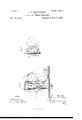
- Figure l is an elevation from one side of the mechanism of the improved electrical visual indicator and annunciator-drop, the side of the inclosing-case being removed to expose the parts, the position of the restoring devices when moved. to reset the parts be ing shown in dotted lines;
- Fig. 2 an elevation of the mechanism from the other side, the annunciator-drop being shown as released inwith the annunciator-drop released, such case.
- Fig. 6,21 side elevation and partial vertical section of one section of the indicator, the locking-hook being shown as engaging the escapeinent-rack in dotted lines
- Fig. 7, a separateelevation of one of the escapement-racks (other than that of the first section) shown as supported previous to being set for action, the locking-hook and retarded actuating-weight of the preceding section being shown in dotted lines.
- A is a suitable case, inclosing and protect- This case supports the binding-posts a a, to which the line-wires are attached.
- B is the operating electro-mag net inclosed within the case. Only one magnet is used to It acts upon an armature carried by a lever, C, which is retracted by an adjustable spring, I).
- a link, 0, which is connected with an arm projecting from a rock-shaft, d.
- This arm is pret'erably one ofthe pallet-arms D, carried by such rock-shaft, of which there. is one for each section of the indicator,
- the arms D project upwardly from the rock-shaft d, and carry pallets, as shown,'in their upper ends, which pallets engage with the teeth of vertically-sliding escapement-racks E, one of such escapementracks being provided for each section of the indicator.
- each rack edges of its slot with teeth 0, the teeth on one side of the slot alternating with those on the The lowermost tooth, e, of each rack is what I term a safety-tooth, which prevents the release of the locking device of the escapement-rack should the rack of the preceding section be locked when the circuit is in other than its nor- .mal condition.
- Th s safety-tooth has no funccapement-rack is attached, so as to work therewith, a c g-rack, g, which preferably has sufficient weight to carry the rack downwardly with rapidity and operate the character-wheels F.
- These character-wheels are mounted upon short shafts, which carry piuions IL, engaging with the cog-racks g.
- Theescapement-racks are guided in their vertical movement by grooved posts Gr and vertical rods H, the rear of each rack sliding in a groove in the face of a post, G, while the arms that support the cograck from each escapement-rack have holes through which the rod H passes.
- a slot in each post G is pivoted a locking and lifting book, i, which is secured to arock-.-haft,j, extending to the next succeeding section,if there is one, and there carrying a supporting-hook,
- Each shaft j has a weight, l, secured eccentrically thereto, which throws the hook i normally out of engagement with the teethf ol the escapement-rack with which it operates, and the hook it normally under a pin, m, on the side of the succeeding escapement-rack.
- All the escapement-racks except that of the first section are provided with a pin, or, engaging a hook, it, while the shat'tj, which carries the locking and lifting hook 'i of the last section, has no supporting-hook it, since there is no succeeding escapentent-rack to be held out of action while this last section is operating.
- Each shai'tj is turned against the counteracting force of its weight I by a weight, which is released when the est-apetnent-rack begins to drop, but whose movement is retarded, so that the escapement-rack can reach the limit of its movement and come to a state of rest on the pallet before it will be locked and raised from said pallet.
- the weight in this mechanism is furnished by pivoted segments 1, which have fingers engaging with the backs of the hooks i and toreing them in succession into the teeth f, locking and raising the escapetnent-racks and releasing the succeeding ones,
- Each segment i has cog-teeth engaging with a pinion on the shaft of a fan, J, which retards the movement of the segment.
- Each fan issomewhat heavier on one side than on the other, which heavier side is brought uppermost when the parts are set for action, so that when the segment is released the overbalanced fan will instantly start the movement.
- Each segment has a pin,-n, which engages with a hooked lever, K, pivoted to the post G, and overweighted at the end opposite the hook, so as to disengage the hook from the pin n.
- the weighted end of the hooked lever is raised by the escapement-rack; but the dropping of the rack allows the weight of the hooked lever to disengage the weighted segment.
- the hooked lever has, however, sutficient play to allow the escapement-rack to drop from its safety-tooth e to its lowermost tooth, e, without releasing the segment.
- Each lever K is limited in its movement by a plate,
- the character-wheels F are provided with numbers, words, or characters, which are exhibited at an opening or openings, L, in the front of the box, and it being further understood that the instrument is in electrical connection with a suitable transmitter adapted to act with it: Normally the escapement-rack of the first section has its lowermost tooth, e, resting on its pallet, while the escapement-racks of the other sections are raised ofi'of their pallets, being supported by the hooks k.
- the armature-lever is moved by the action of the magnet and retracting-spring, and the vibrating pallet allows the escapement-rack to fall a definite number of teeth, depending upon the number of times the circuit is closed and opened, when it will come to rest on the pallet.
- This movement will turn the character-wheel, which has an intermittent movement similar to that of the rack,sioce it is moved directly thereby, as well as being controlled in itsmovementby the rack.
- the drop of the escapement-rack allows the weighted end of the hooked lever K to drop, and the weighted segment is released, it being started by it own weight and that of the over-weighted fan J, and the movement being retarded by the fan.
- the weight of the segment l of the first section keeps the hook i forced into the teethfot' the first rack during the operation of all the other sections of the box, the position of the first rack not being aii'ected by the operation of succeeding racks.
- the first escapementrack is locked with the circuit normal, (either opened or closed, according to the arrangement,) the second rack will drop until its lowermost tooth, e, rests on the pallet; otherwise the safety-tooth e will be caught by the pallet, which will be supported until the normal condition of the circuit is restored, when the pallet will go over to the lowermost tooth, e, and the section will be ready to act.
- This operation continues through as many sections as are used, (one or more,) the only diflerence-beiug that the last section is simply locked without releasing any other section. When the action has ceased the complete signal will appear at the opening or openings of the box.
- a push-button, M is connected by a rod and arm with a rock-shat't,p, which is provided with a numr on the wings N.
- the arms do not commence to raise the racks until after the wings N have started the segments, so that the segments will reach their position before the racks raise the hooked levers K to lock such segments.
- the shafts j are released, and their weights 1 withdraw the hooks i from the teeth f and move the hooks 70 under the pins m.
- the instrument hereinbefore described is a complete indicator, adapted for all uses to which such instruments may be applied.
- the opening (or openings) L in the front of the box is closed by a pivoted or sliding shutter or drop, P, which is arranged to disclose the opening and to itself display a number, word, or character when dropped down.
- the drop has a hook, s, at its upper edge, projecting through an opening in the box when the drop is raised, and engaging a pivoted locking-arm, Q. within the case.
- This arm Q drops by its own weight into engagement with the hook s,locking-thc drop.- It is raised to release the drop by an arm, t, on the shaftjofthelastsection.
- Thearmtstrikesthe arm Q at the same time that the escapementrack of the last section is locked, and the drop is thus allowed to fall only at the completion of the operation of the instrument.
- a pivoted arm R within the case rests normally out of contact with the arm at. Arm R is forced down upon arm at, raising the drop, by a projecting head, a, on one of the wings N, which strikes the arm 1% when the wings are raised to restore the segments.
- the head 2 is preferably the eccentric head of a screw, so that by turning it an adjustment can be made to bring the parts into the desired relative relation.
- the indicator forms an instrument that can be employed upon any line to receive signals
- dicators are adapted for-such as burglarala-rms, police and fire alarms, district-telegraphs, &c.-or for private lines, where codes of signals would be used to take thevplace of telephones, dial or printing telegraphs.
- the dropused in connection with the box makes the indicator especially convenient and efficient for telephone-exchange drops, hotel-annunciators, and for similar purposes, whereit is desirable to show not only the person who is calling, but the person or service wanted.
- the indicators For telephone-exchanges there would preferably be one of the indicators provided for each subscriber, instead of the annunciator drop now universally used.
- the subscriber would be provided with a suitable signal-transmitter, arranged for any number within the limits of the system. The subscribercan readily adjust his transmitter and send the signal, and need not have to communicate his wants to the central station over the telephone-line.
- a subscriber By having an indicator in addition to his telephone, a subscriber,when called up, may be informed of f the number of the person who wants him. For
- hotel-annunciators anumberofroom-transmitters are preferably connected with each indicator, either in multiple are or series.
- the drop would indicate the section or floor of the house and the wheels would show the room and theservice.
- Thetransmitter ate-ach room would be arranged to always send a fixed signal (the number of the room,) while it would be adjustable for the different services, any reasonable number of which could be secured.
- thecom- 5 In an electrical visual indicator, the comhination, with an escapement-rack controlled by a pallet vibrated electro inagnetically, of a lockingdevice engaging such rack directly, and having a retarded movement, substantially as set forth.
- the combination with an escapement-rack controlled by a pallet vibrated electro-magnetically, and having a set oflocking-teeth, of a locking-hook forced into the teeth of the rack by a weight having a retarded movement, and a locking device for the weight, released by thc drop of the escapement-rack, substantially as set forth.
- the combination with a vertically-sliding ESOHINIIIBHB rack controlled by a pallet vibrated electromagnetically, and having a setoflocking-teeth, of a pivoted hook forced into such teeth when the rack has finished its movement, locking such rack, and raising it ofl of the pallet by a pivotal movement of the hook continued atter such hook strikes the looking-teeth, substantially as set forth.
- an electrical visual indicator the combination, with an cscapement-rack controlled by a. pallet vibrated clectro-magnetically, and having a set oflocking-teeth, of a pivoted locking-hook, a weight keeping such hook normally out of engagement with the lockingteeth of the rack, and a Weight having a retarded movement, such latter weight being released by the movement of the escapementrack and forcing said looking-hook into the teeth of the rack, substantially as set forth.
- the combination with two or more escapemeutracks, of character-wheels operated and controlled directly by such racks, vibrating pullets controlllng the racks and operated by one electro-nmgnet, means for supporting the sec 0nd and succeeding racks out of operative connection with the pallets, and means for locking each rack directly at the completion of us movement and raising it off of the pallet, and
- the combination with two escapement-racks controlled by pal lets vibrated electro-magnetically, of a rock-shaft. provided with a locking-hook and a supporting-hook, thrown in opposite directions by the movement of the shaft and acting directly upon the racks, the locking-hook being held normally out of action and the supporting-hook normally in action, and a part having a retarded movement for turning such shaft and throwing the locking-hook into action and the supporting-hook out of action. such part being released by the movement of the first of the two escapemcnt-racks, substantially as set forth.
- the combination with two escapcment-racks, each having locking teeth and one (or each) having a supporting pin or projection, such racks being controlled by pallets vibrated electro-magnetically, of a weighted rock-shaft provided with oppositely-moving locking-hook and supporting-hook, a weighted segment for turning such shaft against its normal tendency, a fan retarding the movement of such segment, and a locking device released by the movement of the first rack for holding such segment, substantially as set forth.
- the combination with the esoat'nce-racks, the vibrating pallets. the weighted segments, and the locking devices, of the rock'shaft having wings and arms-for raising such segments and racks in succession, substantially as set forth.
- the combination with an electromagnetic escapementor escap nlents, ot a plvoted drop, means for locking said drop in a raised position, and means for releasing the drop operated by the locking device ot'nn escapemeut, substantially as set forth.
Landscapes
- Physics & Mathematics (AREA)
- Electromagnetism (AREA)
- General Physics & Mathematics (AREA)
- Warehouses Or Storage Devices (AREA)
Description
(No Model.) 5 Sheets--Sheet 1.
' J. U. MACKENZIE.
ELECTRICAL VISUAL INDIGATOR.
N0; 273,563. Patented Mar.6,188'3.
fittest:
NY PETERS. Plwin-Lillw mphen WasHngwn. B. a
. (No Model.) 5 Sheets-Sheet 2.
J. U. MACKENZIE.
ELECTRICAL VISUAL INDICATOR. No. 273,563. Patented Mar.6,1883.
liw erzwrx (No Model.) sweets-slim a.
J. U. MAGKENZIE. I v ELECTRICAL VISUAL INDICATOR. I
No. 273,563. Patented Mar.6,1883.
m m h.
I (NoModeL) i '5 Sheets-Sheet 4.
J.'U. MACKENZIE.
ELECTRICAL VISUAL INDIGATOR. v No. 273,563. Patented Man-6,1883:
N. FUERS. Phnto-fithognphur. Wlnhinghrz. 0.6.
- (No Model.) I 5 Sheets-$l1eet 5.
J. U. MACKENZIE.
ELECTRICAL VISUAL INDICATOR.
No. 273,563. Patented Mar.6,1883.
Fries.
PATENT JAMES U. MACKENZIE, OF NEW YORK, N. Y.
ELECTRICAL VI SUAL INDICATOR.
SPECIFICATION forming part of Letters Patent No. 273,563, dated March 6, 1883.
Application filed August 12, 1882. (No model.)
To all whom it may concern.-
Be it known that 1, JAMES U. MACKENZIE, of New York city, in the county and State of New York, have invented a certain new and useful Improvement in Electrical Visual Indicators,of which the following is a'specification.
The objcctof the present invention is to produce ah electrical visual indicator capable of use for all the purposes to which such an instrument may be applied, which will be exceedingly cheap, simple, and compact in construction, absolutely reliable in operation, and possessing such durability that it will not readily getout of order in any of its parts, and which, further, by reason of its cheapness, compactness, and reliability, will be adapted for many uses to which the visual indicators heretofore produced could not be applied, such as for in-.
graph service, hotels, or for other similar uses.
A further object of the invention is to pro- I duce an electrical indicator of this character,
more especially designed for uses of the nature before specifically set forth, which will be capable of being substituted for the ordinary electrical annunciator-drop, and will not only indicate the person who calls, as does the ordinary annunciator-drop, but will also show who or what is wanted, thus resulting in a great saving 0t time and increasing largely the convenience and efficiency of the service, whatever it may be, as well as economizing by permitting a reduction of the staff of attendants.
The features of invention are particularly hereinafter setforth, and are pointed out by the claims.
' In the accompanying drawings, forming a part hereof, Figure l is an elevation from one side of the mechanism of the improved electrical visual indicator and annunciator-drop, the side of the inclosing-case being removed to expose the parts, the position of the restoring devices when moved. to reset the parts be ing shown in dotted lines; Fig. 2, an elevation of the mechanism from the other side, the annunciator-drop being shown as released inwith the annunciator-drop released, such case.
ing the parts.
. operate the mechanism.
other side, as will be well understood.
being broken away at one side to show the annunciator-dtop-restoring arm; Fig. 6,21. side elevation and partial vertical section of one section of the indicator, the locking-hook being shown as engaging the escapeinent-rack in dotted lines; Fig. 7, a separateelevation of one of the escapement-racks (other than that of the first section) shown as supported previous to being set for action, the locking-hook and retarded actuating-weight of the preceding section being shown in dotted lines.
The drawings illustrate the mechanism upon an enlarged scale, the size of the parts being considerably reduced in practice; but the instrument may be of the same size or even larger than shown in the drawings.
A is a suitable case, inclosing and protect- This case supports the binding-posts a a, to which the line-wires are attached.
B is the operating electro-mag net inclosed within the case. Only one magnet is used to It acts upon an armature carried by a lever, C, which is retracted by an adjustable spring, I). To the armaturelever U is pivoted a link, 0, which is connected with an arm projecting from a rock-shaft, d. This arm is pret'erably one ofthe pallet-arms D, carried by such rock-shaft, of which there. is one for each section of the indicator, The arms D project upwardly from the rock-shaft d, and carry pallets, as shown,'in their upper ends, which pallets engage with the teeth of vertically-sliding escapement-racks E, one of such escapementracks being provided for each section of the indicator. Each of these racks edges of its slot with teeth 0, the teeth on one side of the slot alternating with those on the The lowermost tooth, e, of each rack is what I term a safety-tooth, which prevents the release of the locking device of the escapement-rack should the rack of the preceding section be locked when the circuit is in other than its nor- .mal condition. Th s safety-tooth has no funccapement-rack is attached, so as to work therewith, a c g-rack, g, which preferably has sufficient weight to carry the rack downwardly with rapidity and operate the character-wheels F. These character-wheels are mounted upon short shafts, which carry piuions IL, engaging with the cog-racks g. Theescapement-racks are guided in their vertical movement by grooved posts Gr and vertical rods H, the rear of each rack sliding in a groove in the face of a post, G, while the arms that support the cograck from each escapement-rack have holes through which the rod H passes. In a slot in each post G is pivoted a locking and lifting book, i, which is secured to arock-.-haft,j, extending to the next succeeding section,if there is one, and there carrying a supporting-hook,
Ir. Each shaft j has a weight, l, secured eccentrically thereto, which throws the hook i normally out of engagement with the teethf ol the escapement-rack with which it operates, and the hook it normally under a pin, m, on the side of the succeeding escapement-rack. All the escapement-racks except that of the first section are provided with a pin, or, engaging a hook, it, while the shat'tj, which carries the locking and lifting hook 'i of the last section, has no supporting-hook it, since there is no succeeding escapentent-rack to be held out of action while this last section is operating. Each shai'tj is turned against the counteracting force of its weight I by a weight, which is released when the est-apetnent-rack begins to drop, but whose movement is retarded, so that the escapement-rack can reach the limit of its movement and come to a state of rest on the pallet before it will be locked and raised from said pallet.
The weight in this mechanism is furnished by pivoted segments 1, which have fingers engaging with the backs of the hooks i and toreing them in succession into the teeth f, locking and raising the escapetnent-racks and releasing the succeeding ones, Each segment i has cog-teeth engaging with a pinion on the shaft of a fan, J, which retards the movement of the segment. Each fan issomewhat heavier on one side than on the other, which heavier side is brought uppermost when the parts are set for action, so that when the segment is released the overbalanced fan will instantly start the movement. Each segment has a pin,-n, which engages with a hooked lever, K, pivoted to the post G, and overweighted at the end opposite the hook, so as to disengage the hook from the pin n. The weighted end of the hooked lever is raised by the escapement-rack; but the dropping of the rack allows the weight of the hooked lever to disengage the weighted segment. The hooked lever has, however, sutficient play to allow the escapement-rack to drop from its safety-tooth e to its lowermost tooth, e, without releasing the segment. Each lever K is limited in its movement by a plate,
0, in order to prevent its displacement should the box containing the mechanism be turned upside down in handling.
The joint operation of the parts thus far described is as follows, it being understood that the character-wheels F are provided with numbers, words, or characters, which are exhibited at an opening or openings, L, in the front of the box, and it being further understood that the instrument is in electrical connection with a suitable transmitter adapted to act with it: Normally the escapement-rack of the first section has its lowermost tooth, e, resting on its pallet, while the escapement-racks of the other sections are raised ofi'of their pallets, being supported by the hooks k. The armature-lever is moved by the action of the magnet and retracting-spring, and the vibrating pallet allows the escapement-rack to fall a definite number of teeth, depending upon the number of times the circuit is closed and opened, when it will come to rest on the pallet. This movement will turn the character-wheel, which has an intermittent movement similar to that of the rack,sioce it is moved directly thereby, as well as being controlled in itsmovementby the rack. The drop of the escapement-rack allows the weighted end of the hooked lever K to drop, and the weighted segment is released, it being started by it own weight and that of the over-weighted fan J, and the movement being retarded by the fan. The finger of the segment strikes the hook i and forces it into the teeth f, raising the escapement-rack slightly, so thatit will clear the pallet and allow it f ee movement. The turning of the rock-shaft j against weight 1 withdraws the supportinghookkfrom beneath the pin m of the next succeeding escapemcnI-rack and allows the second rack to drop upon the pallet. It will be understood that the second rack is supported off of the pallet, while the first rack is falling, by its supporting-hook k, which is withdrawn only when the first rack is locked and raised oiit'ot' the pallet by the pivoted hook i. The weight of the segment l of the first section keeps the hook i forced into the teethfot' the first rack during the operation of all the other sections of the box, the position of the first rack not being aii'ected by the operation of succeeding racks. 1f the first escapementrack is locked with the circuit normal, (either opened or closed, according to the arrangement,) the second rack will drop until its lowermost tooth, e, rests on the pallet; otherwise the safety-tooth e will be caught by the pallet, which will be supported until the normal condition of the circuit is restored, when the pallet will go over to the lowermost tooth, e, and the section will be ready to act. This operation continues through as many sections as are used, (one or more,) the only diflerence-beiug that the last section is simply locked without releasing any other section. When the action has ceased the complete signal will appear at the opening or openings of the box.
To restore the parts to theirnormal position the following devices are used: A push-button, M, is connected by a rod and arm with a rock-shat't,p, which is provided with a numr on the wings N. The arms do not commence to raise the racks until after the wings N have started the segments, so that the segments will reach their position before the racks raise the hooked levers K to lock such segments. At the same time that the segments are raised the shafts j are released, and their weights 1 withdraw the hooks i from the teeth f and move the hooks 70 under the pins m.
' The weight of the wings N and arms 0 returns the restoring devices totheir normal position, leaving the parts ready for action.
The instrument hereinbefore described is a complete indicator, adapted for all uses to which such instruments may be applied.
For some purposes the opening (or openings) L in the front of the box is closed by a pivoted or sliding shutter or drop, P, which is arranged to disclose the opening and to itself display a number, word, or character when dropped down. The drop has a hook, s, at its upper edge, projecting through an opening in the box when the drop is raised, and engaging a pivoted locking-arm, Q. within the case. This arm Q drops by its own weight into engagement with the hook s,locking-thc drop.- It is raised to release the drop by an arm, t, on the shaftjofthelastsection. Thearmtstrikesthe arm Q at the same time that the escapementrack of the last section is locked, and the drop is thus allowed to fall only at the completion of the operation of the instrument. To restore the drop, it is provided with an arm, u, projecting into the case from its lower edge. A pivoted arm R, within the case rests normally out of contact with the arm at. Arm R is forced down upon arm at, raising the drop, by a projecting head, a, on one of the wings N, which strikes the arm 1% when the wings are raised to restore the segments. The head 2: is preferably the eccentric head of a screw, so that by turning it an adjustment can be made to bring the parts into the desired relative relation.
Instead of one drop for the entire box, there may be a drop for each section, which would be released upon the completion of the operation of the particular section. A multiplication of the parts bel'ore described would simply be necessary.
It will be noticed that one of the features of the visual indicator heretofore described is the use of gravity throughout. in the place of spiral or other springs, the action of weights being much more reliable and uniform than that of springs, and the weights have the advantage of permanency, while springs ultimately give out. The construction and arran gement of parts,it will also be seen, are simple and efficient, there being no time adjust ments or knife-edge stops, and, in addition, there is no strain caused by giving'the character-wheels a continuous non-intermittent movement and allowing them at times to gain considerable momentum before being stopped.
The indicator forms an instrument that can be employed upon any line to receive signals,
and may be put to all the uses that visual in-,
dicators are adapted for-such as burglarala-rms, police and fire alarms, district-telegraphs, &c.-or for private lines, where codes of signals would be used to take thevplace of telephones, dial or printing telegraphs. The dropused in connection with the box makes the indicator especially convenient and efficient for telephone-exchange drops, hotel-annunciators, and for similar purposes, whereit is desirable to show not only the person who is calling, but the person or service wanted.
For telephone-exchanges there would preferably be one of the indicators provided for each subscriber, instead of the annunciator drop now universally used. The subscriber would be provided with a suitable signal-transmitter, arranged for any number within the limits of the system. The subscribercan readily adjust his transmitter and send the signal, and need not have to communicate his wants to the central station over the telephone-line. By having an indicator in addition to his telephone, a subscriber,when called up, may be informed of f the number of the person who wants him. For
hotel-annunciators anumberofroom-transmitters are preferably connected with each indicator, either in multiple are or series. The drop would indicate the section or floor of the house and the wheels would show the room and theservice. Thetransmitter ate-ach room would be arranged to always send a fixed signal (the number of the room,) while it would be adjustable for the different services, any reasonable number of which could be secured.
What I claim is 1. In an electrical visual indicator, the combination, with two or more escapement-racks worked by pallets vibrated by one electro-magnet, of character-wheels operated and controlled directly by such escapement-racks, substantially as set forth.
2. In an electrical visual indicator, thecombination, with two or more vertically-sliding escapement-racks controlled by pallets vibrated by one electro-magnet, of a cog-rack carried by each escapement-rack, a characterwheel, and a pinion engaging the cog-rack and turning the character-wheel, substantially as set forth. 1
3. In.an electrical visual indicator, the combination, with two or more escapement-racks controlled by a pallet vibrated by one electromagnet, of a character-wheel for each escapement-rack, and means,independent of the character-wheel, for locking each escapement-rackdirectly at any point of its movement, substantially as set forth.
4. In an electrical visual indicator, thecom- 5. In an electrical visual indicator, the comhination, with an escapement-rack controlled by a pallet vibrated electro inagnetically, of a lockingdevice engaging such rack directly, and having a retarded movement, substantially as set forth.
6. In an electrical visual indicator, the combination, with an escapement-rack controlled by a pallet vibrated electro-magnetically, and having a set oflocking-teeth, of a locking-hook forced into the teeth of the rack by a weight having a retarded movement, and a locking device for the weight, released by thc drop of the escapement-rack, substantially as set forth.
7. In an electrical visual indicator, the combination, with an electromagnetic escapement having locking-teeth, of a locking-hook, a pivoted segment forcing such hook into the teeth of the escapement-rack, and a fan for retarding the movement of the segment, substantially as set forth.
8. In an electrical visual indicator, the combination, with a vertically-sliding ESOHINIIIBHB rack controlled by a pallet vibrated electromagnetically, and having a setoflocking-teeth, of a pivoted hook forced into such teeth when the rack has finished its movement, locking such rack, and raising it ofl of the pallet by a pivotal movement of the hook continued atter such hook strikes the looking-teeth, substantially as set forth.
9. In an electrical visual indicator, the combination, with an cscapement-rack controlled by a. pallet vibrated clectro-magnetically, and having a set oflocking-teeth, of a pivoted locking-hook, a weight keeping such hook normally out of engagement with the lockingteeth of the rack, and a Weight having a retarded movement, such latter weight being released by the movement of the escapementrack and forcing said looking-hook into the teeth of the rack, substantially as set forth.
10. In an electrical visual indicator, the combination, with an escapementrack, of a locking-hook withdrawn normally, a weighted segment forcing such hook into action, a fan for retarding the movement of the segment, and a pivoted hooked lever locking the segment, and raised by the rack, the dropping of such rack releasing the lever and unlocking the segment, substantially as set forth.
11. In an electrical visual indicator, the combination, with two or more escapemeutracks, of character-wheels operated and controlled directly by such racks, vibrating pullets controlllng the racks and operated by one electro-nmgnet, means for supporting the sec 0nd and succeeding racks out of operative connection with the pallets, and means for locking each rack directly at the completion of us movement and raising it off of the pallet, and
releasing at the same time the next succeeding escapementrack, substantially as set forth.
12. In an electrical visual indicator, the combination, with two escapement-racks controlled by pal lets vibrated electro-magnetically, of a rock-shaft. provided with a locking-hook and a supporting-hook, thrown in opposite directions by the movement of the shaft and acting directly upon the racks, the locking-hook being held normally out of action and the supporting-hook normally in action, and a part having a retarded movement for turning such shaft and throwing the locking-hook into action and the supporting-hook out of action. such part being released by the movement of the first of the two escapemcnt-racks, substantially as set forth.
13. In an electrical visual indicator, the combination, with two escapcment-racks, each having locking teeth and one (or each) having a supporting pin or projection, such racks being controlled by pallets vibrated electro-magnetically, of a weighted rock-shaft provided with oppositely-moving locking-hook and supporting-hook, a weighted segment for turning such shaft against its normal tendency, a fan retarding the movement of such segment, and a locking device released by the movement of the first rack for holding such segment, substantially as set forth.
14. In an electrical visual indicator, the combination, with the escapement-racks, vibrating pallets, and locking devices, of the rock-shaft and the arms for raising the racks, substantially as set forth.
15. In an electrical visual indicator, the combination, with the esoat'mment-racks, the vibrating pallets. the weighted segments, and the locking devices, of the rock'shaft having wings and arms-for raising such segments and racks in succession, substantially as set forth.
16. The combination, in an electrically-operated visual indicator, of means for indicating any one of a number of visual signals, and a means indicating a fixed visual signal, substantially as set forth.-
17. The combination, with an electricallyoperated visual indicator indicating any one of a number of visual signals, of a. drop or drops indicating a fixed visual signal and released by the action of the indicator mechanism, substantially as set forth.
18. The combination, with an electrical visual indicator, of a drop or drops released by the action of such indicator, and a restoring device connected with and operated by the restoring device of the indicator mechanism, substantially as set forth.
It). In an electrical visual indicator, the combination, with an electromagnetic escapementor escap nlents, ot a plvoted drop, means for locking said drop in a raised position, and means for releasing the drop operated by the locking device ot'nn escapemeut, substantially as set forth.
20. In an electrical visual indicator, the combination, with an electromagnetic escapelIO IIS
273,568 g a r 5 ment or escapements, of a pivoted drop having an arm projecting within the indicatorcase, a pivoted lever for moving such arm, and a projection from a moving part of the indicator-restoring device for operating such pivoted lever, substantially as set forth.
21. In an electrical visual indicator, the combination, with an electromagnetic escapementor escapements, the locking, supporting, and releasingdevices and the character-wheels, of a pivoted drop and a restoring device resetting both the indicator mechanism and the drop simultaneously, and an adj nstahle connection between the drop and the restoring device for giving the parts the desired relation, I 5 substantially as set forth.
This specification signed and witnessed this 8th day of August, 1882.
' JAMES U. MACKENZIE. Witnesses:
H. W. SEELY, EDWARD H. PYATI.
Publications (1)
| Publication Number | Publication Date |
|---|---|
| US273563A true US273563A (en) | 1883-03-06 |
Family
ID=2342793
Family Applications (1)
| Application Number | Title | Priority Date | Filing Date |
|---|---|---|---|
| US273563D Expired - Lifetime US273563A (en) | mackenzie |
Country Status (1)
| Country | Link |
|---|---|
| US (1) | US273563A (en) |
-
0
- US US273563D patent/US273563A/en not_active Expired - Lifetime
Similar Documents
| Publication | Publication Date | Title |
|---|---|---|
| US273563A (en) | mackenzie | |
| US520234A (en) | kirnan | |
| US702666A (en) | Electric clock-synchronizer. | |
| US402823A (en) | Electric clock | |
| US488388A (en) | Fire-alarm apparatus | |
| US1044151A (en) | Controlling apparatus for cab-stands. | |
| US273033A (en) | Indicator for fire-alarm purposes | |
| US507205A (en) | Electric selecting device | |
| US402929A (en) | Telephone system | |
| US313610A (en) | Messenger-signal and fire-alarm apparatus | |
| US450239A (en) | kirnan | |
| US514128A (en) | Signaling system | |
| US212873A (en) | Improvement in electrical signaling apparatus | |
| US537161A (en) | William h | |
| US514975A (en) | Litkoqraphinq coi | |
| US514279A (en) | sachs | |
| US162953A (en) | Improvement in fire-alarm telegraphs | |
| US507147A (en) | Device for selecting and operating mechanical apparatus | |
| US123808A (en) | Improvement | |
| US165923A (en) | Improvement in telegraphic fire-alarm repeaters | |
| US481847A (en) | Fire-alarm telegraph | |
| US141927A (en) | Improvement in annunciators | |
| US545291A (en) | Fare-register | |
| US688839A (en) | Apparatus for distinguishing genuine from spurious coins. | |
| US582187A (en) | Telephone-controlling device |