US273538A - Edward d - Google Patents
Edward d Download PDFInfo
- Publication number
- US273538A US273538A US273538DA US273538A US 273538 A US273538 A US 273538A US 273538D A US273538D A US 273538DA US 273538 A US273538 A US 273538A
- Authority
- US
- United States
- Prior art keywords
- scraper
- handles
- earth
- ground
- edward
- Prior art date
- Legal status (The legal status is an assumption and is not a legal conclusion. Google has not performed a legal analysis and makes no representation as to the accuracy of the status listed.)
- Expired - Lifetime
Links
- 241000242541 Trematoda Species 0.000 description 5
- 238000007790 scraping Methods 0.000 description 3
- 241000272165 Charadriidae Species 0.000 description 1
- 241000935974 Paralichthys dentatus Species 0.000 description 1
- 239000002184 metal Substances 0.000 description 1
- 230000004048 modification Effects 0.000 description 1
- 238000012986 modification Methods 0.000 description 1
- 239000002023 wood Substances 0.000 description 1
Images
Classifications
-
- E—FIXED CONSTRUCTIONS
- E02—HYDRAULIC ENGINEERING; FOUNDATIONS; SOIL SHIFTING
- E02F—DREDGING; SOIL-SHIFTING
- E02F3/00—Dredgers; Soil-shifting machines
- E02F3/04—Dredgers; Soil-shifting machines mechanically-driven
- E02F3/64—Buckets cars, i.e. having scraper bowls
- E02F3/6454—Towed (i.e. pulled or pushed) scrapers
- E02F3/6463—Towed (i.e. pulled or pushed) scrapers with rotatable scraper bowls for dumping the soil
Definitions
- the object of the invention is the production of a strong, simple, and effective earthscraper that is both self-dumping and selfrighting.
- the distinguishing feature of my device is a pair of straight stilts or handles, which are capable of sliding longitudinally in sockets or sheaths upon the scraper-sides, and are provided with flukes or spurs which cause their automaticforward or backward sliding for the operations of dumping and scraping, respectively.
- the flukes aforesaid, by
- A may'represent the body or scoop proper of any suitable earth-scraper, whether of wood or metal. 7 r
- B are customary spurs from the top edge of the back board, 0, to facilitate reversal from the inverted condition.
- the handle at or about its mid-length.
- D is the bail or clevis, hinged to the scrapersides, as at E, at such height and such distance from the scraper-nose as to cause the scraper, when left at liberty, to slide over the ground surface without either entering the ground or inverting, and so that a slight pressure exerted by the operator upon the handles will, if that pressure be downward, cause the scraper-nose to penetrate the ground, and, if
- the bail-sides are set a sufficient distance laterally from the scraper-sides to permit the entire scraper-body, with its handles and their confining-sheaths, to revolve within it after the temporary forward protrusion of the handles hy the fluke ac ion already spoken of.
- the distinguishing characteristic of my im- 1 provement is the pair of handles F F, which, instead of bein g attached rigidly to the scraper-sides, are made capable of sliding longitudinally within sheaths, staples, or sockets, of which there are two, G G, to each handle.
- Each handle is armed with two oppositelydirected tlukes, H H, preferably attached to The flukes H, by catching slightly in the ground as the scraper is drawn forward by the team in the act of scraping, operate to compel the So handles to assume and retain the rearward or normal position shown in Fig. 1, convenient for manipulation by the operator in the usual way of operating earth-scrapers.
- the flukes H H instead of being attached at the mid-length of the handles, may be attached at their extreme forward ends, (see Figs. 3 and 4,) and said handles be provided with a stop, J, to prevent I00 the handles being drawn out of the sheaths
- I hereunto IO when the implement is being drawn along in set my hand. the capsized condition shown in Fig. 4.
Landscapes
- Engineering & Computer Science (AREA)
- Mechanical Engineering (AREA)
- Mining & Mineral Resources (AREA)
- Civil Engineering (AREA)
- General Engineering & Computer Science (AREA)
- Structural Engineering (AREA)
- Food-Manufacturing Devices (AREA)
Description
2 Sheets-Sheet 1.
(No Model.)
} E.D.HUMPHREYS.
EARTH SCRAPER. P.tented Ma.r.6, 1883.
Lithographan Wiihingfim, n. a
(No Model.) 2 Sheets-Sheet 2.
E. D. HUMPHREYS.
EARTH SGRAPER. I No. 273,538. Patented Mar.6,1883.
[IVE 7 [01 N. PETERS. Phnlo-Lnhn rapher, Washington In;
UNITE STATES PATENT OF ICE,
EDWARD D. HUMPHREYS, 0E CINCINNATI, OHIO, AssIeNoR OF ONE-HALF TO DAVID HUMPHREYS, OF SAME PLAoE.
EARTH-SCRAPER.
SPECIFICATION forming part of Letters Patent No. 273,538, dated March 6, 1883.
' Application filed November 6, 1882. (No model.)
To all whom "it may concern:
Be it known that I, EDWARD D. HUMPH- REYS, of Cincinnati, Hamilton county, Ohio, have invented a new and useful Improvement in Earth-Scrapers, of which the following is a specification. v
The object of the invention is the production of a strong, simple, and effective earthscraper that is both self-dumping and selfrighting.
The distinguishing feature of my device is a pair of straight stilts or handles, which are capable of sliding longitudinally in sockets or sheaths upon the scraper-sides, and are provided with flukes or spurs which cause their automaticforward or backward sliding for the operations of dumping and scraping, respectively. When the scraper is in its proper position for scraping, the flukes aforesaid, by
catching in the ground, prevent the handles taking part in the forward movement of the scraper, and said handles are consequently forced and held to their most rearward posi-. tion, where the operator can conveniently handle them. The scraper having become charged or loaded, and sufficiently lifted at rear to enable the draft to invert it, similar flnkes on the opposite sides of the handles encounter the ground and operate to push the handles vations, showing a modification of my inven-' tion in the normal and dumped conditions.
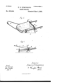
A may'represent the body or scoop proper of any suitable earth-scraper, whether of wood or metal. 7 r
B are customary spurs from the top edge of the back board, 0, to facilitate reversal from the inverted condition.
the handle at or about its mid-length.
D is the bail or clevis, hinged to the scrapersides, as at E, at such height and such distance from the scraper-nose as to cause the scraper, when left at liberty, to slide over the ground surface without either entering the ground or inverting, and so that a slight pressure exerted by the operator upon the handles will, if that pressure be downward, cause the scraper-nose to penetrate the ground, and, if
- upward, will cause the inversion of and consequent dumping of the scraper, followed by its complete somersault. With this object in View, the bail-sides are set a sufficient distance laterally from the scraper-sides to permit the entire scraper-body, with its handles and their confining-sheaths, to revolve within it after the temporary forward protrusion of the handles hy the fluke ac ion already spoken of.
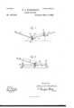
The distinguishing characteristic of my im- 1 provement is the pair of handles F F, which, instead of bein g attached rigidly to the scraper-sides, are made capable of sliding longitudinally within sheaths, staples, or sockets, of which there are two, G G, to each handle. Each handle is armed with two oppositelydirected tlukes, H H, preferably attached to The flukes H, by catching slightly in the ground as the scraper is drawn forward by the team in the act of scraping, operate to compel the So handles to assume and retain the rearward or normal position shown in Fig. 1, convenient for manipulation by the operator in the usual way of operating earth-scrapers. When the implement is inverted (see Fig. 2) the opposite flukes, H, engage in the ground and opcrate, by their resistance, to draw the handles toward the cutting-edge of the scraper, as shown in said figure, so as to permit the scraper-body, with its thus retracted handles, 0 to pass clearthrough the bail in the continued rotation of the body, by which it resumes the normal position.
The above-described preferred form of my improvement may bevaried in non-essential 5 particulars; For example, the flukes H H, instead of being attached at the mid-length of the handles, may be attached at their extreme forward ends, (see Figs. 3 and 4,) and said handles be provided with a stop, J, to prevent I00 the handles being drawn out of the sheaths In testimony of which invention I hereunto IO when the implement is being drawn along in set my hand. the capsized condition shown in Fig. 4.
I claim herein as new and of my invention- EDWARD D. HUMPHREYS. In an earth-scraper, the longitudinally-sliding handles 1 F"in sheaths G G upon the Attest:
scraper-sides, said handles being armed with GEO. H. KNIGHT, oppositely-extending flukes H H, as and for G. F. KNOWLTON. the purposes set forth. 1 1
Publications (1)
| Publication Number | Publication Date |
|---|---|
| US273538A true US273538A (en) | 1883-03-06 |
Family
ID=2342768
Family Applications (1)
| Application Number | Title | Priority Date | Filing Date |
|---|---|---|---|
| US273538D Expired - Lifetime US273538A (en) | Edward d |
Country Status (1)
| Country | Link |
|---|---|
| US (1) | US273538A (en) |
-
0
- US US273538D patent/US273538A/en not_active Expired - Lifetime
Similar Documents
| Publication | Publication Date | Title |
|---|---|---|
| US273538A (en) | Edward d | |
| US1888170A (en) | Digging implement | |
| US637712A (en) | Road-scraper. | |
| US1232361A (en) | Shovel attachment. | |
| US508685A (en) | Scraper | |
| US1201076A (en) | Sink-cleaner. | |
| US791390A (en) | Excavating-scoop. | |
| US1775206A (en) | Scraper | |
| US979047A (en) | Road grader and drag. | |
| US1093558A (en) | Scraper. | |
| US850006A (en) | Ditching-plow. | |
| US320112A (en) | Stable-scraper | |
| US943897A (en) | Ditching-plow. | |
| US484806A (en) | Martin a | |
| US1182779A (en) | Ditching-machine. | |
| US1014293A (en) | Excavating-scoop. | |
| US910384A (en) | Road-grader. | |
| US385003A (en) | Scraper | |
| US660812A (en) | Post-hole digger. | |
| US1782646A (en) | Ground scraper and leveler | |
| US751933A (en) | Scoop | |
| US545748A (en) | Road-scraper | |
| US1793968A (en) | Scraper | |
| US233122A (en) | Dirt-scraper | |
| US10699A (en) | Submarine scoop |