US2734603A - Magnetic fluid clutches - Google Patents
Magnetic fluid clutches Download PDFInfo
- Publication number
- US2734603A US2734603A US2734603DA US2734603A US 2734603 A US2734603 A US 2734603A US 2734603D A US2734603D A US 2734603DA US 2734603 A US2734603 A US 2734603A
- Authority
- US
- United States
- Prior art keywords
- ribs
- fluid
- magnetic
- magnetic fluid
- clutch
- Prior art date
- Legal status (The legal status is an assumption and is not a legal conclusion. Google has not performed a legal analysis and makes no representation as to the accuracy of the status listed.)
- Expired - Lifetime
Links
- 239000011553 magnetic fluid Substances 0.000 title description 78
- 210000000614 Ribs Anatomy 0.000 description 114
- 239000012530 fluid Substances 0.000 description 74
- 230000004907 flux Effects 0.000 description 22
- XEEYBQQBJWHFJM-UHFFFAOYSA-N iron Chemical compound [Fe] XEEYBQQBJWHFJM-UHFFFAOYSA-N 0.000 description 20
- 239000000696 magnetic material Substances 0.000 description 18
- 125000004122 cyclic group Chemical group 0.000 description 12
- 239000000203 mixture Substances 0.000 description 12
- 230000000694 effects Effects 0.000 description 10
- 229910052742 iron Inorganic materials 0.000 description 10
- 239000003921 oil Substances 0.000 description 10
- 239000006249 magnetic particle Substances 0.000 description 8
- 238000001816 cooling Methods 0.000 description 6
- 230000003247 decreasing Effects 0.000 description 6
- 238000009434 installation Methods 0.000 description 6
- 239000000314 lubricant Substances 0.000 description 6
- 239000006247 magnetic powder Substances 0.000 description 6
- 239000002184 metal Substances 0.000 description 6
- 229910052751 metal Inorganic materials 0.000 description 6
- 235000019198 oils Nutrition 0.000 description 6
- 230000005540 biological transmission Effects 0.000 description 4
- 230000015556 catabolic process Effects 0.000 description 4
- 230000000875 corresponding Effects 0.000 description 4
- 238000010438 heat treatment Methods 0.000 description 4
- 239000007788 liquid Substances 0.000 description 4
- 238000004519 manufacturing process Methods 0.000 description 4
- 239000000463 material Substances 0.000 description 4
- 239000003208 petroleum Substances 0.000 description 4
- 239000000843 powder Substances 0.000 description 4
- 229910001369 Brass Inorganic materials 0.000 description 2
- 239000010951 brass Substances 0.000 description 2
- 125000002915 carbonyl group Chemical group [*:2]C([*:1])=O 0.000 description 2
- 229910052802 copper Inorganic materials 0.000 description 2
- 239000010949 copper Substances 0.000 description 2
- RYGMFSIKBFXOCR-UHFFFAOYSA-N copper Chemical compound [Cu] RYGMFSIKBFXOCR-UHFFFAOYSA-N 0.000 description 2
- 230000002708 enhancing Effects 0.000 description 2
- 230000004048 modification Effects 0.000 description 2
- 238000006011 modification reaction Methods 0.000 description 2
- 239000002245 particle Substances 0.000 description 2
- 230000002035 prolonged Effects 0.000 description 2
- 230000000452 restraining Effects 0.000 description 2
- 229920002545 silicone oil Polymers 0.000 description 2
- 239000000126 substance Substances 0.000 description 2
- 230000000153 supplemental Effects 0.000 description 2
- 235000015112 vegetable and seed oil Nutrition 0.000 description 2
- 239000008158 vegetable oil Substances 0.000 description 2
Images

Classifications
-
- F—MECHANICAL ENGINEERING; LIGHTING; HEATING; WEAPONS; BLASTING
- F16—ENGINEERING ELEMENTS AND UNITS; GENERAL MEASURES FOR PRODUCING AND MAINTAINING EFFECTIVE FUNCTIONING OF MACHINES OR INSTALLATIONS; THERMAL INSULATION IN GENERAL
- F16D—COUPLINGS FOR TRANSMITTING ROTATION; CLUTCHES; BRAKES
- F16D37/00—Clutches in which the drive is transmitted through a medium consisting of small particles, e.g. centrifugally speed-responsive
- F16D37/02—Clutches in which the drive is transmitted through a medium consisting of small particles, e.g. centrifugally speed-responsive the particles being magnetisable
-
- F—MECHANICAL ENGINEERING; LIGHTING; HEATING; WEAPONS; BLASTING
- F16—ENGINEERING ELEMENTS AND UNITS; GENERAL MEASURES FOR PRODUCING AND MAINTAINING EFFECTIVE FUNCTIONING OF MACHINES OR INSTALLATIONS; THERMAL INSULATION IN GENERAL
- F16D—COUPLINGS FOR TRANSMITTING ROTATION; CLUTCHES; BRAKES
- F16D37/00—Clutches in which the drive is transmitted through a medium consisting of small particles, e.g. centrifugally speed-responsive
- F16D2037/002—Clutches in which the drive is transmitted through a medium consisting of small particles, e.g. centrifugally speed-responsive characterised by a single substantially axial gap in which the fluid or medium consisting of small particles is arranged
Definitions
- the unit contains an electromagnetic coil to produce the magnetic flux in the gap between the members.
- the coil When the coil is not energized, the only force restraining relative rotation between the two surfaces is that produced by the viscous drag of the fluid in the gap.
- the magnetic particles in the fluid When the coil is energized, the magnetic particles in the fluid are attracted to one another and'to the magnetic driving and driven members by magnetic influence, binding the members together and permitting the transmission of power to an output shaft.
- the device may also be used as a brake when the driven member is held in a fixed position.
- Another limitation of the conventional magnetic fluid clutch is the excessive heating of the magnetic fluid under slip conditions. This heating is particularly noticeable in and is confined to that part of the magnetic fluid immediately adjacent the driving and driven member surfaces and may result in the breakdown or degeneration of the fluid.
- a further limitation of the magnetic fluid clutch as now constructed is a tendency for the iron or magnetic particles in the magnetic fluid to centrifuge outwardly during operation of the clutch, often permanently locking the co-acting clutch surfaces together or to settle out when the unmagnetized fluid is at rest.
- Another object of the present invention is to provide a magnetic fluid clutch wherein heat transfer from the region of the surface of the rotating surfaces is enhanced.
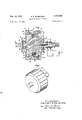
- Fig. l is a side elevation, cross-sectional view of a typical magnetic fluid clutch embodying the present invention.
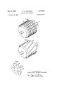
- Fig. 2 is a perspective View of the driven rotor of a magnetic fluid clutch illustrating the present invention.
- Fig. 3 is a plot of tangential force exerted on the driven member of the clutch versus the flux density.
- Fig. 4 is a logarithmic plot of torque output versus rotor diameter.
- Figs. 5 through 7 are illustrative of variations in the arrangement of the components of this invention.
- Magnetic fluid clutches have been made heretofore with various types of finishes on the opposing surfaces.
- the surfaces have been polished, machine finished, and even roughened with serrations. It was found that the serrated surface actually decreased the tangential force at the surface of the clutch member, causing a reduction in the power output of the clutch.
- the ribs or teeth serve to mix the magnetic fluid and prevent the creation of an overheated layer of fluid contiguous to the rotating driving surface, provide fin-like surfaces for the dissipation of heat from the magnetized fluid, and may even be used to circulate the fluid along the clutch surface and through a cooling reservoir.
- These ribs or teeth are to be distinguished from the grooves set forth in copending application Serial No. 188,009, new Patent No. 2,605,876, issued August 5, 1952 assigned to the same assignee as the present invention.
- ribs be of non-magnetic material. It will be appreciated that the presence of magnetic ribs would cause cyclic variations in the torque produced by changes in the reluctance of the magnetic path as the rib surfaces move relative to one another. If magnetic teeth are used, there is also a reduction in possible torque inasmuch as the flux tends to pass through the projecting teeth instead of through the relatively much larger surfaces between the teeth. On the other hand, using non-magnetic ribs, the only influence changing the reluctance of the magnetic path is due to the very shallow channels in the surface which might be used to receive the ribs.
- the channels or slots in which the ribs are fixed are very shallow and very narrow compared to the distance between ribs, there is little or no deviation of the magnetic flux lines.
- the ribs or teeth are formed in the surface itself this latter effect will be entirely absent.
- the ribs project about 0.020 inch above the surfaces of the driving and driven members.
- the slots in which the ribs are based are about 0.040 inch deep while the width of the ribs is about 0.032 inch.
- the distance between ribs is typically 0.625 inch in such an installation, or about 20 times the rib width, it will 7 further to reduce the small amount of influence due to the slots forming in effect low projecting ribs or poles of magnetic material, the number of teeth on the driven and driving surfaces may be made unequal in number.
- the driving member may have 40 slots while the driven surface has only 39 slots. The net effect here is to reduce even more the already negligible cyclic variation. of the torque.
- the driven member 1 comprises a rotor 2 of magnetic material such as iron, having fixed thereto or integral there with an output or driven shaft 3.
- Rotor 2 is magnetized by means of an electromagnetic coil 4 mounted within the periphery of the rotor as shown and connected by leads 5 and 6 through a conduit in the rotor 2 and shaft 3 to slip rings 7 and 8 fixed in shaft 3, and insulated from one another and fromthe shaft 3 by an insulating member 9.
- Slip rings 7 and 8 are connected through contact brushes l0 and if to a unidirectional voltage source 12 through switch 13.
- a portion of the rotor may be cut away to form a recess as shown to receive the coil which is held in place by a ring 14 fixed to the rotor in any convenient manner as by bolting and non-magnetic ring 31.
- ribs 16 Mounted lengthwise in slot 15 and the periphery of rotor 2 are ribs 16 of non-magnetic material with their length disposed axially along the rotor andtheir height extending radially. These ribs are better shown in Fig. 2 which is a perspective view of driven member 1.
- slots 15 are about 0.040 inch deep and the ribs seated in the slot project about 0.020 inch above the circumference of the rotor.
- the ribs 16 are about 0.032 inch wide and spaced about 0.625 inch apart, measuring from their centers.
- a six inch diameter rotor would then have about 30 ribs or projections arranged about its circumference.
- the above details are for the purpose of a specific example only and that the dimensions of the ribs and their spacial arrangement may be varied considerably.
- the ribs should not project a distance from the rotor WhlCll lS more than about one quarter of the gap distance between the driving and driven members.
- the driving member 17 as shown is in the form,- of a cage which surrounds driven member ll and'output shaft 3.
- Driving member 17 is constructed of a number of fitted components.
- the ends 18 and 19 of the cage.- hke driving member are of nonmagnetic metal and have fitted between them as shown a ring 20 of magnetic metal which is dovetailed in place and fitted with seals 21 to prevent the passage of liquid through the. joint.
- An input shaft member 22 comprising a flange 23 and input shaft 24 is fixed'to. member 19. Bearingslfi are placed between. the shaft of the driven member and the driving member as shown.
- Shaft seals 26 serve to prevent the flow of liquid along, the shafts from the space between the. driven and driving members.
- Ribs or projections 27 similar to ribs 16 of therotor are placed in the inner periphery of ring 20 in which receiving slots 28 are cut.
- the space 29 between the driving and driven members is filled with a normally fluid iron-oil mixture iatl.
- Typical proportions of such mixtures are five to seven parts by weight of carbonylfE iron'powder to one part by weight: of SAE; 10-petroleumoil.
- ribs or teeth of the present invention have een described herein as having a particular configuration, that" is, arranged axially along the driving cage and the driven rotor of. a magnetic fluid clutch
- other configurations may be used to obtain the benefit of increased torque as well as to promote the mixing of the magnetic fluid.
- under prolonged slip conditions while the. fluid is magnetized there is a tendency for the layer of iron-oil fluid contiguous to the rotating driving member to become heated. The temperature of such layer may rise to as high as 300 or 400 resulting often in a physical and chemical breakdown of the oil component.
- the present ribs have a salutary effect in keeping, the magnetized fluid well mixed under such slip conditions and promotes the transfer of heat from heated layer to the rest of the fluid and to the other parts of the clutch. It-has also been found that'the cooling of the magnetized fluid may beenhanced by placing ribs or projections at right angles to those which extend axially along the co-acting surfaces.
- One such configuration of ribs is that in- Fig; 5' wherein rotor 2 is depicted as having rectangular, axially arranged'ribs 16 and in addition ribs 35 disposed at right angle to ribs 16.
- Such'an arrangement produces an increase in torque over a smooth engaging surface and at the same time enhances the mixing and. cooling. of the magnetized fluid.
- the fluid be circulated from one end of the rotor to the other along the engaging surfaces.
- the straight ribs 16 may bereplaced byribs 36 of Fig. G-arranged helically aroundthe periphery of the rotor to force the fluid over the surface thus distributing the. heat more.
- ribs on the disc type clutch 37 in Fig. 7 may be arranged radially on the face of driven disc 38 as well as on the corresponding driving member. Other specific arrangements of the ribs or projections will occur to those skilled in the art.
- the present ribs may also be employed in clutches wherein the engaging surfaces are in the shape of cones, hemispheres and the like. If the height of the present ribs or teeth is maintained at not more than about one-quarter of the gap distance there is little or no increase in the viscous drag of the fluid over ordinary surfaces.
- the ribs of the present invention also are useful in that by keeping the unmagnetized fluid in a mixed condition when the driving member is in motion with the driven member stationary, the tendency of the magnetic particles in the fluid to centrifuge or settle out is counteracted. Consequently, there is less occasion, using the present ribs, for the surfaces to jam or lock due to packing of the magnetic particles between the co-acting surfaces.
- magnetic fluid clutches which produce an output torque substantially larger than that produced by conventional types of magnetic clutches.
- clutches in which the unmagnetized fluid is kept mixed and heat transfer enhanced under slip conditions. At the same time centrifuging tendencies of the fluid are reduced.
- means for circulating the unmagnetized fluid along the face of the clutch surfaces during slip conditions are provided.
- a pair of members spaced with their faces in juxtaposition and relatively rotatable on a common axis one member comprising a magnetic material having embedded therein an electromagnet, means to energize said electromagnet, said one member having a shaft connected thereto, the other member comprising a magnetic material and having a shaft connected thereto, and a magnetic fluid comprising a mixture of a magnetic powder and a lubricant in the space between the faces of said spaced members, whereby when said electromagnet is energized, flux passes between said members through said fluid tending to bind said members for transmission of torque between said shafts, the faces of said members having ribs aflixed thereto in mutually spaced relation, said ribs being positioned at an angle to the direction of fluid flow during relative rotation of said members to create turbulence in the flow of said magnetic fluid, and said ribs being non-magnetic to prevent cyclic variations in said flux passing between said members whereby cyclic variations in torque produced in one shaft by rotation of the
- a magnetic fluid clutch a pair of spaced members relatively rotatable on a common axis and having faces in juxtaposition, a magnetic fluid comprising a mixture of a magnetic powder and a lubricant between the faces of said members, and teeth aflixed to the coacting faces of said spaced members, said teeth being of non-magnetic material so as to prevent production thereby of cyclic flux and torque variations upon relative rotation of said faces, said teeth on one face being in spaced relation to those on the juxtaposed face, the height of said teeth being no more than one fourth of the distance between said spaced members, and being angularly disposed to the direction of fluid flow whereby turbulent flow is imparted to the fluid passing between said teeth.
- a magnetic fluid clutch a pair of spaced members relatively rotatable on a common axis and having coacting faces in juxtaposition, a magnetic fluid comprising a mixture of a magnetic powder and a lubricant between said faces, and helically arranged, axially extending ribs on said faces, said ribs being of non-magnetic material so as to prevent production thereby of cyclic flux and torque variations upon relative rotation of said faces, the ribs on one face being in spaced relation to those on the coacting face, both sets of ribs being angularly disposed to the direction of fluid flow between faces whereby turbulence is imparted to said magnetic fluid.
Description
1956 K. E. WAKEFIELD MAGNETIC FLUID CLUTCHES 3 Sheets-Sheet 1 Filed Sept. 29, 1950 Inventor: Kenneth E.Wake.Fie.ld,
His Attorney.
Feb. 14, 1956 K. E. WAKEFIELD MAGNETIC FLUID CLUTCHES 3 Sheets-Sheet 2 Filed Sept. 29, 1950 I 4 FLUX 0E/vs/7'y K/LOGHU-SSES 391 MSQQE P v, m m tWL w n2. 4% Wm M 2 m w w Feb. 1956 K. E. WAKEFIELD MAGNETIC FLUID CLUTCHES 3 Sheets-Sheet 3 Filed Sept. 29, 1950 4% His Attorney.
H E a .tW 5 h t he n n United States Patent MAGNETIC FLUID CLUTCHES Kenneth E. Wakefield, Schenectady, N. Y., assignor to General Electric Company, a corporation of New York Application September 29, 1950, Serial No. 187,577
3 Claims. (Cl. 192-215) discs, a rotor within a cylinder, concentric cylinders, or
parallel surfaces of other configurations which are relatively rotatable about a common axis. The unit contains an electromagnetic coil to produce the magnetic flux in the gap between the members. When the coil is not energized, the only force restraining relative rotation between the two surfaces is that produced by the viscous drag of the fluid in the gap. When the coil is energized, the magnetic particles in the fluid are attracted to one another and'to the magnetic driving and driven members by magnetic influence, binding the members together and permitting the transmission of power to an output shaft. The device may also be used as a brake when the driven member is held in a fixed position.
While magnetic fluid clutches have been eminently successful in many applications, as now constructed they are subject to several limitations. One of these limitations is caused by slippage between the magnetized fluid and the driving. and driven members and manifests itself in reduced tangential force between the fluid and the rotating members. This places a low limit on the possible output torque.
Another limitation of the conventional magnetic fluid clutch is the excessive heating of the magnetic fluid under slip conditions. This heating is particularly noticeable in and is confined to that part of the magnetic fluid immediately adjacent the driving and driven member surfaces and may result in the breakdown or degeneration of the fluid.
A further limitation of the magnetic fluid clutch as now constructed is a tendency for the iron or magnetic particles in the magnetic fluid to centrifuge outwardly during operation of the clutch, often permanently locking the co-acting clutch surfaces together or to settle out when the unmagnetized fluid is at rest.
It is an object of this invention to increase the output torque of magnetic fluid clutches.
Another object of the present invention is to provide a magnetic fluid clutch wherein heat transfer from the region of the surface of the rotating surfaces is enhanced.
It is also an object of this invention to provide a magnetic fluid clutch wherein, under slip conditions with the magnetic fluid unmagnetized, the latter is maintained in a mixed condition.
It is a further object of this invention to provide a magnetic fluid clutch wherein the tendency of the rotating members to slip relative to the magnetic fluid when the latter is magnetized is decreased.
It is a still further object of the invention to reduce ice the tendency towards centrifuging the iron particles in the fluid when the latter is not magnetized.
Other objects will become apparent from a consideration of the following description and the drawing. Fig. l is a side elevation, cross-sectional view of a typical magnetic fluid clutch embodying the present invention. Fig. 2 is a perspective View of the driven rotor of a magnetic fluid clutch illustrating the present invention. Fig. 3 is a plot of tangential force exerted on the driven member of the clutch versus the flux density. Fig. 4 is a logarithmic plot of torque output versus rotor diameter.
Figs. 5 through 7 are illustrative of variations in the arrangement of the components of this invention.
It has been found that the foregoing objects may be readily accomplished by providing ribs on the opposing clutch surfaces. More particularly, it has been found that the above objects may be realized by placing projections or ribs of non-magnetic material on the opposing surfaces of magnetic fluid clutches.
Magnetic fluid clutches have been made heretofore with various types of finishes on the opposing surfaces. For example, the surfaces have been polished, machine finished, and even roughened with serrations. It was found that the serrated surface actually decreased the tangential force at the surface of the clutch member, causing a reduction in the power output of the clutch.
It has now been found that if ribs or teeth of nonmagnetic material such as brass, copper, or other material, which can withstand the forces involved, are placed on, embedded in, affixed to, or formed in the clutch surfaces, the tendency toward slippage between the magnetized fluid and the clutch surfaces at their interfaces is decreased and the driving force proportionally increased;
Under slip conditions the ribs or teeth serve to mix the magnetic fluid and prevent the creation of an overheated layer of fluid contiguous to the rotating driving surface, provide fin-like surfaces for the dissipation of heat from the magnetized fluid, and may even be used to circulate the fluid along the clutch surface and through a cooling reservoir. These ribs or teeth are to be distinguished from the grooves set forth in copending application Serial No. 188,009, new Patent No. 2,605,876, issued August 5, 1952 assigned to the same assignee as the present invention.
It is essential, in order to realize the full benefit of this invention, that ribs be of non-magnetic material. It will be appreciated that the presence of magnetic ribs would cause cyclic variations in the torque produced by changes in the reluctance of the magnetic path as the rib surfaces move relative to one another. If magnetic teeth are used, there is also a reduction in possible torque inasmuch as the flux tends to pass through the projecting teeth instead of through the relatively much larger surfaces between the teeth. On the other hand, using non-magnetic ribs, the only influence changing the reluctance of the magnetic path is due to the very shallow channels in the surface which might be used to receive the ribs. However, since the channels or slots in which the ribs are fixed are very shallow and very narrow compared to the distance between ribs, there is little or no deviation of the magnetic flux lines. Of course, if the ribs or teeth are formed in the surface itself this latter effect will be entirely absent. In a typical installation, using a six inch diameter rotor as the driven member, the ribs project about 0.020 inch above the surfaces of the driving and driven members. The slots in which the ribs are based are about 0.040 inch deep while the width of the ribs is about 0.032 inch. When it is considered that the distance between ribs is typically 0.625 inch in such an installation, or about 20 times the rib width, it will 7 further to reduce the small amount of influence due to the slots forming in effect low projecting ribs or poles of magnetic material, the number of teeth on the driven and driving surfaces may be made unequal in number. Thus. the driving membermay have 40 slots while the driven surface has only 39 slots. The net effect here is to reduce even more the already negligible cyclic variation. of the torque.
The operation of the invention will be better understood by reference to the drawing. In Fig. 1 th e shown in cross-section a typical cylinder-rotor type magnetic fluid clutch embodying the present concept. The driven member 1 comprises a rotor 2 of magnetic material such as iron, having fixed thereto or integral there with an output or driven shaft 3. Rotor 2 is magnetized by means of an electromagnetic coil 4 mounted within the periphery of the rotor as shown and connected by leads 5 and 6 through a conduit in the rotor 2 and shaft 3 to slip rings 7 and 8 fixed in shaft 3, and insulated from one another and fromthe shaft 3 by an insulating member 9. Slip rings 7 and 8 are connected through contact brushes l0 and if to a unidirectional voltage source 12 through switch 13.
In order to facilitate the mounting of coil 4 within rotor 2, a portion of the rotor may be cut away to form a recess as shown to receive the coil which is held in place by a ring 14 fixed to the rotor in any convenient manner as by bolting and non-magnetic ring 31. Mounted lengthwise in slot 15 and the periphery of rotor 2 are ribs 16 of non-magnetic material with their length disposed axially along the rotor andtheir height extending radially. These ribs are better shown in Fig. 2 which is a perspective view of driven member 1. As pointed out above, in a typical installation as shown having a six inch diameter rotor, slots 15 are about 0.040 inch deep and the ribs seated in the slot project about 0.020 inch above the circumference of the rotor. in the typical arrangement the ribs 16 are about 0.032 inch wide and spaced about 0.625 inch apart, measuring from their centers. A six inch diameter rotor would then have about 30 ribs or projections arranged about its circumference. It will be understood that the above details are for the purpose of a specific example only and that the dimensions of the ribs and their spacial arrangement may be varied considerably. In general, the ribs should not project a distance from the rotor WhlCll lS more than about one quarter of the gap distance between the driving and driven members. In other words, the-ribs, projections,
or teeth on one face are in spaced relationship with and.
do not interlock with those on the co-acting face. It should also be borne in mind that the circumferential space between ribs should be great compared to the width of the ribs.
The driving member 17 as shown is in the form,- of a cage which surrounds driven member ll and'output shaft 3. Driving member 17 is constructed of a number of fitted components. The ends 18 and 19 of the cage.- hke driving member are of nonmagnetic metal and have fitted between them as shown a ring 20 of magnetic metal which is dovetailed in place and fitted with seals 21 to prevent the passage of liquid through the. joint. An input shaft member 22 comprising a flange 23 and input shaft 24 is fixed'to. member 19. Bearingslfi are placed between. the shaft of the driven member and the driving member as shown. Shaft seals 26 serve to prevent the flow of liquid along, the shafts from the space between the. driven and driving members. Ribs or projections 27 similar to ribs 16 of therotor are placed in the inner periphery of ring 20 in which receiving slots 28 are cut.
The space 29 between the driving and driven members is filled with a normally fluid iron-oil mixture iatl. Typical proportions of such mixtures are five to seven parts by weight of carbonylfE iron'powder to one part by weight: of SAE; 10-petroleumoil.
In; place of,
42 petroleum oil other oils including vegetable oils and synthetic oils may be used, the particular characteristics of the fluid being varied to suit specific installations.
As in the operation of the usual magnetic fluid clutch, a rotating force or torque is applied to input shaft 24. With coil 4 unenergized, the driving member 17 merely rotates about driven member 1 and no rotational tangential force is transmitted to the latter except from a negligible force. attributable to the viscous drag of fluid 30. However, when coil 4 is energized by closing switch 13, theparticles of magnetic metal in fluid 30' magnetize and align themselves in a myriad of chains between they now magnetized magnetic rotor 2 and magnetic ring 20 of the driving member in effect to combine the driving and driven members into a unitary system. Under such conditions, any torque applied to input shaft 24 is transferred through fluid 30 to driven member 1 and causes output shaft 3 to rotate.
In actual practice, using a magnetic fluid clutch of the type shown in Fig. l but without the magnetic ribs or teeth of the present invention; the tangential force in pounds per square inch varies with the flux density in kilogausses as shown in curve 3'1 of Fig. 3. On the other hand, when the parallel co-acting magnetic surfaces or clutches are fitted with. the present ribs or projections as described above, the tangential force per square inch of area is increased substantially at flux densities above seven kilogausses as shown in curved 32.
The torque in' pound-feet for usual magnetic fluid clutches and rotors of various diameters is shown in curve 34' of Fig. 4. Reference to curve 33 which gives corresponding values for clutches of the present invention having projections or ribs described herein, reveals that a substantial increase in torque is realized by the use of the ribs. For example, the increase in torque with a clutch having a five inch diameter rotor is about 5.0%. This increase is typical of clutches having rotors of other diameters. The curves of Fig. 3 as well as Fig. 4 were obtained using a fluid consisting of five parts by weight of carbonyl E iron powder and one part by weight of silicone oil.
While the ribs or teeth of the present invention have een described herein as having a particular configuration, that" is, arranged axially along the driving cage and the driven rotor of. a magnetic fluid clutch, other configurations may be used to obtain the benefit of increased torque as well as to promote the mixing of the magnetic fluid. As pointed out above, under prolonged slip conditions while the. fluid is magnetized there is a tendency for the layer of iron-oil fluid contiguous to the rotating driving member to become heated. The temperature of such layer may rise to as high as 300 or 400 resulting often in a physical and chemical breakdown of the oil component. It has been found that the present ribs have a salutary effect in keeping, the magnetized fluid well mixed under such slip conditions and promotes the transfer of heat from heated layer to the rest of the fluid and to the other parts of the clutch. It-has also been found that'the cooling of the magnetized fluid may beenhanced by placing ribs or projections at right angles to those which extend axially along the co-acting surfaces. One such configuration of ribs is that in- Fig; 5' wherein rotor 2 is depicted as having rectangular, axially arranged'ribs 16 and in addition ribs 35 disposed at right angle to ribs 16. Such'an arrangement produces an increase in torque over a smooth engaging surface and at the same time enhances the mixing and. cooling. of the magnetized fluid.
lncertain applications it is desirable that the fluid be circulated from one end of the rotor to the other along the engaging surfaces. In such case the straight ribs 16 may bereplaced byribs 36 of Fig. G-arranged helically aroundthe periphery of the rotor to force the fluid over the surface thus distributing the. heat more.
uniformly throughout the system; The'ribs 36-add substantially to the torque produced when the fluid is magnetized. It will be understood of course that the ribs above described are placed on the driving as well as the driven surface.
The benefits of the present invention are obtainable when using disc and other type magnetic fluid clutches as well as the rotor type most particularly described herein. For example, ribs on the disc type clutch 37 in Fig. 7 may be arranged radially on the face of driven disc 38 as well as on the corresponding driving member. Other specific arrangements of the ribs or projections will occur to those skilled in the art. The present ribs may also be employed in clutches wherein the engaging surfaces are in the shape of cones, hemispheres and the like. If the height of the present ribs or teeth is maintained at not more than about one-quarter of the gap distance there is little or no increase in the viscous drag of the fluid over ordinary surfaces.
The ribs of the present invention also are useful in that by keeping the unmagnetized fluid in a mixed condition when the driving member is in motion with the driven member stationary, the tendency of the magnetic particles in the fluid to centrifuge or settle out is counteracted. Consequently, there is less occasion, using the present ribs, for the surfaces to jam or lock due to packing of the magnetic particles between the co-acting surfaces.
By this invention there are provided magnetic fluid clutches which produce an output torque substantially larger than that produced by conventional types of magnetic clutches. There are provided also clutches in which the unmagnetized fluid is kept mixed and heat transfer enhanced under slip conditions. At the same time centrifuging tendencies of the fluid are reduced. There are provided also means for circulating the unmagnetized fluid along the face of the clutch surfaces during slip conditions.
While the present invention has been described with reference to certain embodiments, it is to be understood that it is desired to protect herein all those modifications obvious to those skilled in the art which do not depart from the spirit and scope of the invention.
What I claim as new and desire to secure by Letters Patent of the United States is:
1. In combination, a pair of members spaced with their faces in juxtaposition and relatively rotatable on a common axis, one member comprising a magnetic material having embedded therein an electromagnet, means to energize said electromagnet, said one member having a shaft connected thereto, the other member comprising a magnetic material and having a shaft connected thereto, and a magnetic fluid comprising a mixture of a magnetic powder and a lubricant in the space between the faces of said spaced members, whereby when said electromagnet is energized, flux passes between said members through said fluid tending to bind said members for transmission of torque between said shafts, the faces of said members having ribs aflixed thereto in mutually spaced relation, said ribs being positioned at an angle to the direction of fluid flow during relative rotation of said members to create turbulence in the flow of said magnetic fluid, and said ribs being non-magnetic to prevent cyclic variations in said flux passing between said members whereby cyclic variations in torque produced in one shaft by rotation of the other is prevented.
2. In a magnetic fluid clutch, a pair of spaced members relatively rotatable on a common axis and having faces in juxtaposition, a magnetic fluid comprising a mixture of a magnetic powder and a lubricant between the faces of said members, and teeth aflixed to the coacting faces of said spaced members, said teeth being of non-magnetic material so as to prevent production thereby of cyclic flux and torque variations upon relative rotation of said faces, said teeth on one face being in spaced relation to those on the juxtaposed face, the height of said teeth being no more than one fourth of the distance between said spaced members, and being angularly disposed to the direction of fluid flow whereby turbulent flow is imparted to the fluid passing between said teeth.
3. In a magnetic fluid clutch, a pair of spaced members relatively rotatable on a common axis and having coacting faces in juxtaposition, a magnetic fluid comprising a mixture of a magnetic powder and a lubricant between said faces, and helically arranged, axially extending ribs on said faces, said ribs being of non-magnetic material so as to prevent production thereby of cyclic flux and torque variations upon relative rotation of said faces, the ribs on one face being in spaced relation to those on the coacting face, both sets of ribs being angularly disposed to the direction of fluid flow between faces whereby turbulence is imparted to said magnetic fluid.
References Cited in the file of this patent UNITED STATES PATENTS OTHER REFERENCES Bureau of Standards'Technical Report 1213, National Bureau of Standards, Washington, D. C. (Copy received in the Patent Oflice March 30, 1948.)
Supplemental Information on Magnetic Fluid Clutch, National Bureau of Standards, May 9, 1949.
Magnetic Fluid Clutch, K. E. Wakefield, General Electric Review, December 1949, pages 39 to 43.
Publications (1)
| Publication Number | Publication Date |
|---|---|
| US2734603A true US2734603A (en) | 1956-02-14 |
Family
ID=3444086
Family Applications (1)
| Application Number | Title | Priority Date | Filing Date |
|---|---|---|---|
| US2734603D Expired - Lifetime US2734603A (en) | Magnetic fluid clutches |
Country Status (1)
| Country | Link |
|---|---|
| US (1) | US2734603A (en) |
Cited By (2)
| Publication number | Priority date | Publication date | Assignee | Title |
|---|---|---|---|---|
| US2890774A (en) * | 1956-02-01 | 1959-06-16 | Richard D Parker | Magnetic fluid clutch with speed control therefor |
| FR2618503A1 (en) * | 1987-07-24 | 1989-01-27 | Inst Francais Du Petrole | Force-transmission device for applying a specific drive torque to a rotating element |
Citations (8)
| Publication number | Priority date | Publication date | Assignee | Title |
|---|---|---|---|---|
| US473042A (en) * | 1892-04-19 | Peter william will ans | ||
| US1101997A (en) * | 1913-03-20 | 1914-06-30 | Nathan Edmond Church | Electromagnetic brake. |
| US2525571A (en) * | 1948-05-21 | 1950-10-10 | Martin P Winther | Dynamoelectric machine containing a magnetic fluid mixture |
| US2543394A (en) * | 1949-04-16 | 1951-02-27 | Martin P Winther | Magnetic clutch |
| FR976917A (en) * | 1948-10-26 | 1951-03-23 | Method of absorption or transmission of couples, devices allowing the implementation and their applications | |
| US2604964A (en) * | 1949-01-21 | 1952-07-29 | Martin P Winther | Magnetic fluid mixture clutch with plow |
| US2605876A (en) * | 1950-10-02 | 1952-08-05 | Gen Electric | Magnetic clutch |
| GB677726A (en) * | 1948-04-02 | 1952-08-20 | Benton Hall Schaub | Improvements in or relating to clutches and controlling means therefor |
-
0
- US US2734603D patent/US2734603A/en not_active Expired - Lifetime
Patent Citations (8)
| Publication number | Priority date | Publication date | Assignee | Title |
|---|---|---|---|---|
| US473042A (en) * | 1892-04-19 | Peter william will ans | ||
| US1101997A (en) * | 1913-03-20 | 1914-06-30 | Nathan Edmond Church | Electromagnetic brake. |
| GB677726A (en) * | 1948-04-02 | 1952-08-20 | Benton Hall Schaub | Improvements in or relating to clutches and controlling means therefor |
| US2525571A (en) * | 1948-05-21 | 1950-10-10 | Martin P Winther | Dynamoelectric machine containing a magnetic fluid mixture |
| FR976917A (en) * | 1948-10-26 | 1951-03-23 | Method of absorption or transmission of couples, devices allowing the implementation and their applications | |
| US2604964A (en) * | 1949-01-21 | 1952-07-29 | Martin P Winther | Magnetic fluid mixture clutch with plow |
| US2543394A (en) * | 1949-04-16 | 1951-02-27 | Martin P Winther | Magnetic clutch |
| US2605876A (en) * | 1950-10-02 | 1952-08-05 | Gen Electric | Magnetic clutch |
Cited By (2)
| Publication number | Priority date | Publication date | Assignee | Title |
|---|---|---|---|---|
| US2890774A (en) * | 1956-02-01 | 1959-06-16 | Richard D Parker | Magnetic fluid clutch with speed control therefor |
| FR2618503A1 (en) * | 1987-07-24 | 1989-01-27 | Inst Francais Du Petrole | Force-transmission device for applying a specific drive torque to a rotating element |
Similar Documents
| Publication | Publication Date | Title |
|---|---|---|
| US2575360A (en) | Magnetic fluid torque and force transmitting device | |
| US2525571A (en) | Dynamoelectric machine containing a magnetic fluid mixture | |
| US2605876A (en) | Magnetic clutch | |
| US2886151A (en) | Field responsive fluid couplings | |
| US2661825A (en) | High fidelity slip control | |
| US2519449A (en) | Magnetic drive | |
| US2718292A (en) | Magnetic clutch | |
| US2543394A (en) | Magnetic clutch | |
| US2601076A (en) | Magnetic fluid mixture clutch | |
| US3777864A (en) | Air cooled magnetic clutch and brake | |
| US2884107A (en) | Oil-cooled electromagnetic brake or clutch | |
| US2738044A (en) | Electromagnetic plate clutch | |
| US2587077A (en) | Labyrinth seal | |
| US2620900A (en) | Electromagnetic braking device | |
| US2845157A (en) | Magnetic fluid clutch with permanent magnets | |
| US2734603A (en) | Magnetic fluid clutches | |
| US2693261A (en) | Magnetic disk clutch | |
| US2822070A (en) | Magnetic clutch | |
| US2745527A (en) | Magnetic fluid mixture clutch | |
| US5713444A (en) | Electromagnetic brake/clutch | |
| US3028737A (en) | Couple | |
| US2818148A (en) | Magnetic fluid clutch with laminated rotor | |
| US2705064A (en) | Electromagnetic fluid mixture clutch | |
| US2444797A (en) | Magnetic coupling | |
| US3177998A (en) | Magnetic clutch with a magnetic lining |