US2713251A - Bulk milk cooler - Google Patents
Bulk milk cooler Download PDFInfo
- Publication number
- US2713251A US2713251A US429066A US42906654A US2713251A US 2713251 A US2713251 A US 2713251A US 429066 A US429066 A US 429066A US 42906654 A US42906654 A US 42906654A US 2713251 A US2713251 A US 2713251A
- Authority
- US
- United States
- Prior art keywords
- milk
- sump
- walls
- liner
- wall
- Prior art date
- Legal status (The legal status is an assumption and is not a legal conclusion. Google has not performed a legal analysis and makes no representation as to the accuracy of the status listed.)
- Expired - Lifetime
Links
- 239000008267 milk Substances 0.000 title description 37
- 210000004080 milk Anatomy 0.000 title description 37
- 235000013336 milk Nutrition 0.000 title description 37
- 239000007788 liquid Substances 0.000 description 34
- 239000003507 refrigerant Substances 0.000 description 32
- XLYOFNOQVPJJNP-UHFFFAOYSA-N water Substances O XLYOFNOQVPJJNP-UHFFFAOYSA-N 0.000 description 14
- 238000007710 freezing Methods 0.000 description 7
- 230000008014 freezing Effects 0.000 description 7
- 238000005192 partition Methods 0.000 description 7
- 238000001816 cooling Methods 0.000 description 6
- 238000009413 insulation Methods 0.000 description 4
- 238000005057 refrigeration Methods 0.000 description 4
- 230000015572 biosynthetic process Effects 0.000 description 3
- 230000036760 body temperature Effects 0.000 description 2
- 239000002826 coolant Substances 0.000 description 2
- 238000011010 flushing procedure Methods 0.000 description 2
- 230000008018 melting Effects 0.000 description 2
- 238000002844 melting Methods 0.000 description 2
- 230000002093 peripheral effect Effects 0.000 description 2
- 241000257303 Hymenoptera Species 0.000 description 1
- 239000012080 ambient air Substances 0.000 description 1
- 238000010276 construction Methods 0.000 description 1
- 238000000151 deposition Methods 0.000 description 1
- 238000012423 maintenance Methods 0.000 description 1
Images


Classifications
-
- A—HUMAN NECESSITIES
- A01—AGRICULTURE; FORESTRY; ANIMAL HUSBANDRY; HUNTING; TRAPPING; FISHING
- A01J—MANUFACTURE OF DAIRY PRODUCTS
- A01J9/00—Milk receptacles
- A01J9/04—Milk receptacles with cooling arrangements
-
- F—MECHANICAL ENGINEERING; LIGHTING; HEATING; WEAPONS; BLASTING
- F25—REFRIGERATION OR COOLING; COMBINED HEATING AND REFRIGERATION SYSTEMS; HEAT PUMP SYSTEMS; MANUFACTURE OR STORAGE OF ICE; LIQUEFACTION SOLIDIFICATION OF GASES
- F25D—REFRIGERATORS; COLD ROOMS; ICE-BOXES; COOLING OR FREEZING APPARATUS NOT OTHERWISE PROVIDED FOR
- F25D31/00—Other cooling or freezing apparatus
- F25D31/006—Other cooling or freezing apparatus specially adapted for cooling receptacles, e.g. tanks
Definitions
- This invention relates to milk coolers and more paricularly to milk coolers of the bulk tank type.
- the present hivention is primarily directed to a milk cooler of the stated character in which a secondary liquid medium is tlushed down over the exterior walls of a tank containing milk in bulk to al'ord rapid reduction in the temperature thereof from body heat to the vicinity of 40 F. in a relatively short period of time, and the maintenance ot this reduced temperature despite the depositing in the tank from time to time of additional quantities of body temperature milk.
- the invention contemplates essentially the provision of a milk cooler having a secondary heat exchange system wherein the secondary medium is directed to flow both over the external surfaces of the bulk tank and over the interior surfaces of the cabinet itself, on which surfaces are mounted refrigerant coils of the primary system.
- An operating cycle has been devised which will permit the formation of an ice bank on the walls of the cabinet adjacent the primary coils, which ice bank is stripped from these walls by the secondary medium warmed by contact with the mill -bearing tank.
- the cycle of operations of the pump, the compressor and the expansion valve of the primary system is controlled and arranged so that the optimum temperature conditions can be maintained at all times in the bulk tank, regar less of the initial milk temperature and the time interval between milk deposits.
- a principal object of the invention is to provide a milk cooler in which the optimum temperature for storage of milk can readily be maintained.
- a further object of the invention is to provide in a milkcooler of the stated character, means by which heat from milk is absorbed directly by a primary refrigerant system, by a secondary liquid medium and by the melting of a preformed ice bank.
- further obi-ect of the invention is to provide a milk cooler of the stated type wherein the temperature responsive means controlling the operation of the primary system is positioned to control the formation of the ice bank and is directly affected by the secondary medium warmen by contact with milk at body temperature.
- a final object o the invention is to provide a milk cooler of the primary-secondary heat exchange type wherein the sensing means for the expansion Valve of the primary system is arranged to respond rapidly to the needs or" the system and to afford a steady mean storage temperature.
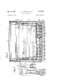
- Fig. l is an elevational View partly in section of the preferred form of the invention.
- Fig. 2 is a view taken substantially on line 2 2 of Fig. l;
- Fig. 3 is a View taken substantially on line 3 3 or' Fig. l;
- FIG. 4 is a view taken substantially on line 4 4 of Fig. 3;
- Fig. 5 is a view taken substantially on line 5 5 of Fig. 2;
- Fig. 6 is a fragmentary view of a modved form of the invention.
- Fig, 7 is a view taken substantially on line 7 7 of Fig. 6;
- Fig. 8 is a View in perspective of the gutter and spout arrangement of Figs. 6 and 7.
- the illustrated embodiment of the invention comprises a cabinet having an outer Shell 1, and a partition wail 2 dividing the cabinet into a minor corntfnent 3a, in which are positioned the customary con- Ants of refrigerating system, and a major cornp'.. nt having a liner 5 positioned in spaced relation to the shell l and the wall 2.
- Suitable insulation 6 is positioned between the liner, the outer shell, and Wall 2 f to reduce the passage of extraneous heat into the major compartment to a minimum.
- the liner 5 comprises an end wall 5a, side wall 5b, end wall 5c, side Wall 5d, and bottom wall Se.
- the primary refrigeration system used in the milk cooler of the present invention is of standard construction and the compressor is indicated generally by the reference numeral 2S.
- Refrigerant such as Freon, or the like, is forced from the compressor to the condenser 26 and from thence by means of the conduit 27 to the expansion valve 28 and expansion coil 16.
- the coil lo comprises generally two parallel sections extending from a T-iltting 2li to either side of the major compartment.
- one section 16a of this coil is bonded to the liner wall 5b and is connected in series to a section 16h which is bonded to the support members 7 approximately midway of their heighths.
- a coil section 16C is bonded to the liner wall 5d and is connected in series to coil section 16d, secured to the support members 7 at the opposite side of the The ends of the coil sections 1Gb and ld are connected to a T-t ⁇ 1tting 21 from whence the refrigerant flows by means of a suitable conduit 22 back to the primary refrigeration apparatus.
- the secondary refrigerant system includes a pump 29 actuatable by a motor 32.
- a quantity of secondary re frigerant is normally maintained in the sump 33 at the bottom of the major compartment 4.
- the secondary liquid is drawn from the sump by the pump 29 through a pipe 34 and forced by way of a conduit 35 into a tubular manifold 36 which is secured to the side and end walls of the major compartment above the step 37.
- This manifold 36 is provided with two radially spaced series of longitudinally spaced apertures arranged to direct the secondary medium against the sides 38 of the bulk milk tank 3 and against the step 37 so that a portion ows down over the coil sections bonded to the walls of the liner.
- the flow of the secondary medium may be controlled so that an ice bank of predetermined thickness can be formed on the liner walls adjacent the coil sections to attain a high degree of uniformity of cooling.
- a time switch 42 shown schematically in Fig. l, may be set so that the pump 29 will operate for only a predetermined period of time. It will be understood that the control of the secondary medium is independent of the control of the primary system.
- the compressor 25 ofthe primary system is responsive only to temperature and is started and stopped by means of a bulb 43, mounted by means of rubber grommets 44 in a U-shaped bracket 45 secured to the side of one of the support members 7 in spaced relation to the innermost run of coil section 16h. lt will be apparent that accurate regulation of the compressor is possible because of the proximity of the bulb 43 to the liquid owing from sides of the bulk milk tank. Its position not only controls the amount of ice built Vup on the runs of the coil sections 16b and 16d, but
- a bulb 46 controls the operation of the expansion valve 28 and permits the expansion of more or less refrigerant in the primary system as required.
- This bulb is arranged in a shell 47 which is secured in heat conductive relation to the ycommon hot gas line within the major compartment so as to be responsive thereto and to the temperature of the liquid in the sump in which the bulb 46 is immersed, as clearly shown in Fig. 2.
- the sump drain valve 4S is closed and the sump is filled with suicient secondary liquid medium, preferably to the level shown in Fig. 2.
- the compressor 25 is then turned on by means of a suitable switch (not shown) and the timer 42 is set to start operation of the pump 29 so that the secondary medium will be sprayed ontov theside walls of the liner to form a sheet of ice thereon which eventually will reach the thickness of about l/z".
- the dairyman may set the timer for a part load for one milking, if desired, to cause the pump 29 to operate for a sucient length of time to accommodate the normal quantity of milk from each milking.
- the expansion valve 28 tends to restrict the flow of refrigerant to the coil sections in response to the bulb 46.
- the ice bank on the walls and the coil section 16b and 16d will have been built up to the desired thickness and likewise the ice will have almost enveloped ⁇ the bulb 43.
- the compressor 25 continues to operate until the bulb 43 is completely enveloped. Since heat leakage from the ambient air is inevitable, the cornpressor will continue to operate intermitently to maintain the icel bank on the several coil sections. The'time of this continued operation will vary depending upon the amount of insulation employed and other design characteristics, and will occur despite the fact that the milk tank is empty, y
- the dairyman When the bulk milk which normally has a temperature of about 90 F., is deposited in the' tank, the dairyman again sets the timer which actuates the pump 29 for a predetermined interval during which the secondary liquid is sprayed both over the walls of the milk tank and against the side walls of the liner as shown clearly in. Fig. 1.
- the heat from the milk warms the secondary liquid so that the flow thereof over the side walls rapidly strips the ice from these walls so that it falls in slabs either against the bulk tank or into the sump.
- This stripping action forms an important part of thepresent invention, in thatV the advantages both of mechanical and ice refrigeration are obtained by the consequent flow of liquid over the bare liner walls and over both sides of the iceslabs. Constant recirculation of the liquid swiftly reduces the temperature of the milk. After a short period of operation in this manner under heat load, the bulb 43 is uncovered and the compressor 25' is reactuated.
- the liquid reaches its maximum temperature of about 43 F. and yall the'ice in the cabinet is melted.
- Both the compressor and the pump continue to operate so that the ice begins to build up inside the cabinet as soon as the temperature of the liquid has reached approximately 39 F.
- the bulb 46 maintains the expansion valve 28 in a fully open position to assure maximum flow of refrigerant.
- the new layer of ice continues to build up on the side Walls and the bottom 'coil sections until the bulb 46 is again covered.
- the compressor operates as required to compensate for heat leakage and uniformity of refrig- ⁇ eration as well as stability of control is achieved. Since the operation of the pump is controlled by the timer 42, formation of ice is terminated on the expiration of the set time. Additional milk may thereafter be added at any time. In that event the timer is reset and the stripping operation is repeated.
- control system cooperates particularly with the secondary heat exchange system effectively to cool in a brief time relatively large quantities of milk. This result is attained because of the heat absorbed simultaneously by the secondary liquid owing over the walls of the milk tank during the predetermined interval of pump operation, by the primary refrigerant coils, and by the melting of the ice slab, after the latter has been stripped from the coils.
- a modified form of the invention wherein a gutter or atrough 49 comprising two downwardly and inwardly inclined sections 49a and 49b are attached to one end of the bulk tank. Liquid flowing down the walls of the bulk tank ows into these trough sections and thence into the spout 52 from which it ows into the immediate vicinity of the control bulb 43.
- the bulb becomes increasingly sensitive to the liquid ilowing directly from the walls of the milk container, the time interval between the initial stripping of the ice slabs and the commencing'of operation of the compressor is shortened, and the operation of the compressor is controlled with a high degree of accuracy to reduce swiftlythetemperature of the sump in said cabinet beneath the bottom Wall of said container, means associated with said sump for impelling water from said sump to other portions of the interior of said container, said means including a conduit having outlets directed against an upp'er part of the interior of the wall portion of the cabinet to flush said wall portion, refrigerant circulating conduit means mounted in closely coupled freezing relation to said flushed wall portion to freeze liquid flushed thereover, and means for passing refrigerant through said refrigerant circulating conduitmeans to freeze liquid on said vertical wall portion, whereby water rst flushed against said wall portion operates to remove into said sump ice previously ⁇ formed against said wall portion, and water ushed against saidV wall portion in continued operation isfrozen to form a
- a cooling apparatus for liquids comprising an open top cabinet having a wall portion surrounding the liquid-containing space to be cooled, a
- container for the liquid to be cooled mounted within said wall portion and having its peripheral wall portions closely surrounded by the peripheral wall of said cabinet and a top openin@ underlying the open top of said cabinet, a sump in said cabinet beneath the bottom wall cf said container, means associated with said sump for pelling water from said samp to other portions of the interior of said container, said means including a conduit having outlets directed against an upper part of the interior of the wall portion of the cabinet to tlush wall portion and other outlets directed inwardly against the outer surface of said container, refrigerant circulating conduit means mounted in closely coupled freezing relation against the interior of said flushed wall portion to freeze liquid liushed thereover, and means for passing refrigerant through said refrigerant c ating conduit means to freeze liquid on said vertical ll portion, whereby water first flushed against said wall portion operates to remove into said sump ice previously formed against said wall portion, and water ned against sai-1. wall portion in continued operation is frozen to form a fresh layer of ice against said
- a cabinet having exterior side and end walls and a bottom wall and a top wall and a partition dividing the interior thereof into a major compartment and a minor compartment, a liner disposed in said major compartment in spaced relation to said walls and said partition, said liner having side and end walls an; a bottom wall, insulation disposed between said liner and said exterior walls and said partition, a container arranged in said major compartment in proximate spaced relation to said liner for the reception of milk in bulk form, a sump in the bottom of said major compartment, a primary refrigeration system including a compressor and a condenser positioned in said minor compartment, and an evaporator coil having sections arranged in series on each of said side walls and coil sections disposed substantially midway between the bottom of said container and the bottom wall of said liner, a secondary refrigerant system operative to direct liquid cooling medium over the walls of said liner and said container to form an ice baril; on said liner walls, timing means to control the flow of secondary refrigerant
- cooler a cabinet having exterior side and end walls, a bottom wall and a top wall and a partition dividing the interior thereof into a major compartment and a minor compartment, a liner disposed in said major compartment in spaced relation to said walls and sai.; partition, said liner having side and end walls and a bottom wall, insulation disposed between said liner and said exterior walls and said partition, a container arranged in said major compartment in proximate spaced relationl to said liner for the reception of milk in bulk form, 1; sump in the bottom of said major compartment, a primary efrigeration system including a compressor and a condenser positioned in said minor compartment and an evaporator coil having sections secured to each of said side walls of said liner, and coil sections disposed between the bottom of said container and the bottom wall of said liner, a secondary refrigerant system operative to direct liquid cooling medium over the walls of said liner and said container to form an ice bank on said liner walls, timing means to
- a milk cooler according to claim 4 wherein further temperature responsive means are mounted in said major compartment in proximate relation to the end of said evaporator coil, said last-named temperature responsive means being operative to control the flow of refrigerant into said evaporator coil.
- a cooling apparatus for liquids comprising a cabinet having a vertically extending wall portion adjacent the liquid-containing space to be cooled, means for mounting a container for the liquid to be cooled adjacent said wall portion, a sump in said cabinet, means associated with said sump for impelling water from said sump to other portions of the interior of said container, said means including a conduit having outlets directed against a container mounted adjacent said wall to liush the outer surface of said container and extract heat therefrom, and outlets directed against the ripper portion of said Wall, refrigerant circulating conduit means mounted in closely coupled freezing relation to said iiushed Wall portion to freeze liquid ushed thereover, refrigerant circulating conduit means also mounted within said sump, means for passing refrigerant through said refrigerant circulating conduit means in closely coupled freezing relation to said llushed wall portion and said refrigerant circulating conduit means Within said sump, a thermostat mounted within said sump, means controlled by said thermostat to control the refrigerating action within said refriger
- a cooling apparatus for liquids comprising a cabinet having a vertically extending wall portion adjacent the liquid-containing space to be cooled, means for mounting a container for the liquid to be cooled adjacent said wall portion, a sump in said cabinet, means associated with said sump for impelling water from said sump to other portions of the interior of said container, said means including a conduit having outlets directed against a container mounted adjacent said wall to ush the outer surface of said container and extract heat therefrom, and outlets directed against the upper portion of said Wall, refrigerant circulating conduit means mounted in closely coupled freezing relation to said ushed Wall portion to freeze liquid ushed thereover, refrigerant circulating conduit means also mounted Within said sump, means for passing refrigerant through said refrigerant circulating conduit means in closely coupled freezing relation to said flushed wall portion and said refrigerant circulating conduit means within said sump, a thermostat mounted within said sump, means controlled by said thermostat to control the refrigerating action within said refrigerant circulating' conduit
Landscapes
- Engineering & Computer Science (AREA)
- Life Sciences & Earth Sciences (AREA)
- Animal Husbandry (AREA)
- Environmental Sciences (AREA)
- Chemical & Material Sciences (AREA)
- Combustion & Propulsion (AREA)
- Physics & Mathematics (AREA)
- Mechanical Engineering (AREA)
- Thermal Sciences (AREA)
- General Engineering & Computer Science (AREA)
- Devices That Are Associated With Refrigeration Equipment (AREA)
Description
July 19, 1955 H. E. cANN, SR., ETAL 2,713,251
BULK MILK COOLER Filed May ll, 1954 3 Sheecs-Sheet l July 19, 1955 H. E. CANN, SR., ET AL BULK MILK COOLER 3 Sheets-Sheet 2 Filed May ll, 1954 July 19, 1955 H. E. cANN, SR., ET AL 2,713,251
BULK MILK COOLER 5 Sheets-Sheet 5 Filed May ll, 1954 United States Patent Vuil einer Miur coornn Harry E. Carin, Sr., and Merrill B. Cami, West Chester, Pa., assignors to Esco CabiuetCompnny, West Chester, Pa., a corporation of Pennsyivania Application lyay il, i954, Serial No. 42,066
7 Claims. (Cl. 62-4) This invention relates to milk coolers and more paricularly to milk coolers of the bulk tank type.
The present hivention is primarily directed to a milk cooler of the stated character in which a secondary liquid medium is tlushed down over the exterior walls of a tank containing milk in bulk to al'ord rapid reduction in the temperature thereof from body heat to the vicinity of 40 F. in a relatively short period of time, and the maintenance ot this reduced temperature despite the depositing in the tank from time to time of additional quantities of body temperature milk.
The invention contemplates essentially the provision of a milk cooler having a secondary heat exchange system wherein the secondary medium is directed to flow both over the external surfaces of the bulk tank and over the interior surfaces of the cabinet itself, on which surfaces are mounted refrigerant coils of the primary system. An operating cycle has been devised which will permit the formation of an ice bank on the walls of the cabinet adjacent the primary coils, which ice bank is stripped from these walls by the secondary medium warmed by contact with the mill -bearing tank.
The cycle of operations of the pump, the compressor and the expansion valve of the primary system is controlled and arranged so that the optimum temperature conditions can be maintained at all times in the bulk tank, regar less of the initial milk temperature and the time interval between milk deposits.
A principal object of the invention, therefore, is to provide a milk cooler in which the optimum temperature for storage of milk can readily be maintained.
A further object of the invention is to provide in a milkcooler of the stated character, means by which heat from milk is absorbed directly by a primary refrigerant system, by a secondary liquid medium and by the melting of a preformed ice bank.
further obi-ect of the invention is to provide a milk cooler of the stated type wherein the temperature responsive means controlling the operation of the primary system is positioned to control the formation of the ice bank and is directly affected by the secondary medium warmen by contact with milk at body temperature.
A final object o the invention is to provide a milk cooler of the primary-secondary heat exchange type wherein the sensing means for the expansion Valve of the primary system is arranged to respond rapidly to the needs or" the system and to afford a steady mean storage temperature.
The invention resides further in certain structural details hereinafter described and illustrated in the attached drawings wherein:
Fig. l is an elevational View partly in section of the preferred form of the invention;
Fig. 2 is a view taken substantially on line 2 2 of Fig. l;
Fig. 3 is a View taken substantially on line 3 3 or' Fig. l;
= major compartment.
Ffice Fig. 4 is a view taken substantially on line 4 4 of Fig. 3;
Fig. 5 is a view taken substantially on line 5 5 of Fig. 2;
Fig. 6 is a fragmentary view of a modiiled form of the invention;
Fig, 7 is a view taken substantially on line 7 7 of Fig. 6; and,
Fig. 8 is a View in perspective of the gutter and spout arrangement of Figs. 6 and 7.
VJith reference to the drawings and more particularly to Figs. l and 2, the illustrated embodiment of the invention comprises a cabinet having an outer Shell 1, and a partition wail 2 dividing the cabinet into a minor corntfnent 3a, in which are positioned the customary con- Ants of refrigerating system, and a major cornp'.. nt having a liner 5 positioned in spaced relation to the shell l and the wall 2. Suitable insulation 6 is positioned between the liner, the outer shell, and Wall 2 f to reduce the passage of extraneous heat into the major compartment to a minimum. Mounted within the major compartment on the support members 7 in proximate spaced relation to the liner is a container 8 for the re- Cep-tion of milk in bulk form. Access to this tank is afforded by lids itl, which with top wall 9 completes the enclosure orr the cabinet. The liner 5 comprises an end wall 5a, side wall 5b, end wall 5c, side Wall 5d, and bottom wall Se.
The primary refrigeration system used in the milk cooler of the present invention is of standard construction and the compressor is indicated generally by the reference numeral 2S. Refrigerant, such as Freon, or the like, is forced from the compressor to the condenser 26 and from thence by means of the conduit 27 to the expansion valve 28 and expansion coil 16. The coil lo comprises generally two parallel sections extending from a T-iltting 2li to either side of the major compartment. In particular, one section 16a of this coil is bonded to the liner wall 5b and is connected in series to a section 16h which is bonded to the support members 7 approximately midway of their heighths. Similarly, a coil section 16C is bonded to the liner wall 5d and is connected in series to coil section 16d, secured to the support members 7 at the opposite side of the The ends of the coil sections 1Gb and ld are connected to a T-t`1tting 21 from whence the refrigerant flows by means of a suitable conduit 22 back to the primary refrigeration apparatus.
The secondary refrigerant system includes a pump 29 actuatable by a motor 32. A quantity of secondary re frigerant is normally maintained in the sump 33 at the bottom of the major compartment 4. The secondary liquid is drawn from the sump by the pump 29 through a pipe 34 and forced by way of a conduit 35 into a tubular manifold 36 which is secured to the side and end walls of the major compartment above the step 37. This manifold 36 is provided with two radially spaced series of longitudinally spaced apertures arranged to direct the secondary medium against the sides 38 of the bulk milk tank 3 and against the step 37 so that a portion ows down over the coil sections bonded to the walls of the liner.
The flow of the secondary medium may be controlled so that an ice bank of predetermined thickness can be formed on the liner walls adjacent the coil sections to attain a high degree of uniformity of cooling. A time switch 42, shown schematically in Fig. l, may be set so that the pump 29 will operate for only a predetermined period of time. It will be understood that the control of the secondary medium is independent of the control of the primary system. The compressor 25 ofthe primary system is responsive only to temperature and is started and stopped by means of a bulb 43, mounted by means of rubber grommets 44 in a U-shaped bracket 45 secured to the side of one of the support members 7 in spaced relation to the innermost run of coil section 16h. lt will be apparent that accurate regulation of the compressor is possible because of the proximity of the bulb 43 to the liquid owing from sides of the bulk milk tank. Its position not only controls the amount of ice built Vup on the runs of the coil sections 16b and 16d, but
also on the other coil sections. For example, ice would rst form on the walls 5a and 5d in the vicinity of the runs of the coil sections 16b and 16d simultaneously. Since ice will form lasten the coil sections beneath the bulk tank and then envelop the bulb 43, thecompressor will remain operative until this takes place. In this manner, very accurate control over the compressor operation is attained. This particular relation of bulb 43 with respect to the bottom of the liner and the normal Y level of secondary medium is extremely important to attainment of uniform regulation of the compressor and to prevent the complete freezing over of the liquid in the sump.
A bulb 46controls the operation of the expansion valve 28 and permits the expansion of more or less refrigerant in the primary system as required. This bulb is arranged in a shell 47 which is secured in heat conductive relation to the ycommon hot gas line within the major compartment so as to be responsive thereto and to the temperature of the liquid in the sump in which the bulb 46 is immersed, as clearly shown in Fig. 2.
v In operation, the sump drain valve 4S is closed and the sump is filled with suicient secondary liquid medium, preferably to the level shown in Fig. 2. The compressor 25 is then turned on by means of a suitable switch (not shown) and the timer 42 is set to start operation of the pump 29 so that the secondary medium will be sprayed ontov theside walls of the liner to form a sheet of ice thereon which eventually will reach the thickness of about l/z". The dairyman may set the timer for a part load for one milking, if desired, to cause the pump 29 to operate for a sucient length of time to accommodate the normal quantity of milk from each milking. As the heat Yis removed from the secondary refrigerant, the expansion valve 28 tends to restrict the flow of refrigerant to the coil sections in response to the bulb 46. At this time, the ice bank on the walls and the coil section 16b and 16d will have been built up to the desired thickness and likewise the ice will have almost enveloped `the bulb 43. After the operation of the pump 29 has been terminated by the action of the timer 42 at the end of the setinterval the compressor 25 continues to operate until the bulb 43 is completely enveloped. Since heat leakage from the ambient air is inevitable, the cornpressor will continue to operate intermitently to maintain the icel bank on the several coil sections. The'time of this continued operation will vary depending upon the amount of insulation employed and other design characteristics, and will occur despite the fact that the milk tank is empty, y
When the bulk milk which normally has a temperature of about 90 F., is deposited in the' tank, the dairyman again sets the timer which actuates the pump 29 for a predetermined interval during which the secondary liquid is sprayed both over the walls of the milk tank and against the side walls of the liner as shown clearly in. Fig. 1. The heat from the milk warms the secondary liquid so that the flow thereof over the side walls rapidly strips the ice from these walls so that it falls in slabs either against the bulk tank or into the sump. This stripping action forms an important part of thepresent invention, in thatV the advantages both of mechanical and ice refrigeration are obtained by the consequent flow of liquid over the bare liner walls and over both sides of the iceslabs. Constant recirculation of the liquid swiftly reduces the temperature of the milk. After a short period of operation in this manner under heat load, the bulb 43 is uncovered and the compressor 25' is reactuated.
During the interval between the starting of the pump and the starting ofthe compressor, the liquid reaches its maximum temperature of about 43 F. and yall the'ice in the cabinet is melted. Both the compressor and the pump continue to operate so that the ice begins to build up inside the cabinet as soon as the temperature of the liquid has reached approximately 39 F. During this period of operation the bulb 46 maintains the expansion valve 28 in a fully open position to assure maximum flow of refrigerant. The new layer of ice continues to build up on the side Walls and the bottom 'coil sections until the bulb 46 is again covered. YDuring the time of storage of the chilled milk, the compressor operates as required to compensate for heat leakage and uniformity of refrig-` eration as well as stability of control is achieved. Since the operation of the pump is controlled by the timer 42, formation of ice is terminated on the expiration of the set time. Additional milk may thereafter be added at any time. In that event the timer is reset and the stripping operation is repeated.
The above described control systemcooperates particularly with the secondary heat exchange system effectively to cool in a brief time relatively large quantities of milk. This result is attained because of the heat absorbed simultaneously by the secondary liquid owing over the walls of the milk tank during the predetermined interval of pump operation, by the primary refrigerant coils, and by the melting of the ice slab, after the latter has been stripped from the coils.
In Figs. 6 and 7 a modified form of the invention is disclosed wherein a gutter or atrough 49 comprising two downwardly and inwardly inclined sections 49a and 49b are attached to one end of the bulk tank. Liquid flowing down the walls of the bulk tank ows into these trough sections and thence into the spout 52 from which it ows into the immediate vicinity of the control bulb 43. In this manner, the bulb becomes increasingly sensitive to the liquid ilowing directly from the walls of the milk container, the time interval between the initial stripping of the ice slabs and the commencing'of operation of the compressor is shortened, and the operation of the compressor is controlled with a high degree of accuracy to reduce swiftlythetemperature of the sump in said cabinet beneath the bottom Wall of said container, means associated with said sump for impelling water from said sump to other portions of the interior of said container, said means including a conduit having outlets directed against an upp'er part of the interior of the wall portion of the cabinet to flush said wall portion, refrigerant circulating conduit means mounted in closely coupled freezing relation to said flushed wall portion to freeze liquid flushed thereover, and means for passing refrigerant through said refrigerant circulating conduitmeans to freeze liquid on said vertical wall portion, whereby water rst flushed against said wall portion operates to remove into said sump ice previously` formed against said wall portion, and water ushed against saidV wall portion in continued operation isfrozen to form a fresh layer of ice against said vertical wall portion as the operation of cooling and ushing progresses toward completion. Y
2. In a cooling apparatus for liquids, the combination comprising an open top cabinet having a wall portion surrounding the liquid-containing space to be cooled, a
container for the liquid to be cooled mounted within said wall portion and having its peripheral wall portions closely surrounded by the peripheral wall of said cabinet and a top openin@ underlying the open top of said cabinet, a sump in said cabinet beneath the bottom wall cf said container, means associated with said sump for pelling water from said samp to other portions of the interior of said container, said means including a conduit having outlets directed against an upper part of the interior of the wall portion of the cabinet to tlush wall portion and other outlets directed inwardly against the outer surface of said container, refrigerant circulating conduit means mounted in closely coupled freezing relation against the interior of said flushed wall portion to freeze liquid liushed thereover, and means for passing refrigerant through said refrigerant c ating conduit means to freeze liquid on said vertical ll portion, whereby water first flushed against said wall portion operates to remove into said sump ice previously formed against said wall portion, and water ned against sai-1. wall portion in continued operation is frozen to form a fresh layer of ice against said vertical wall portion as the operation of cooling and flushing progresses toward completion.
3. in a milk cooler, a cabinet having exterior side and end walls and a bottom wall and a top wall and a partition dividing the interior thereof into a major compartment and a minor compartment, a liner disposed in said major compartment in spaced relation to said walls and said partition, said liner having side and end walls an; a bottom wall, insulation disposed between said liner and said exterior walls and said partition, a container arranged in said major compartment in proximate spaced relation to said liner for the reception of milk in bulk form, a sump in the bottom of said major compartment, a primary refrigeration system including a compressor and a condenser positioned in said minor compartment, and an evaporator coil having sections arranged in series on each of said side walls and coil sections disposed substantially midway between the bottom of said container and the bottom wall of said liner, a secondary refrigerant system operative to direct liquid cooling medium over the walls of said liner and said container to form an ice baril; on said liner walls, timing means to control the flow of secondary refrigerant as required, and ten-.vperature responsive means mounted in said sump in spaced relation to said bottom evaporator coil section, said temperature responsive means being operatively connected to said compressor to control the starting and stopping thereof.
4. ln a mill: cooler, a cabinet having exterior side and end walls, a bottom wall and a top wall and a partition dividing the interior thereof into a major compartment and a minor compartment, a liner disposed in said major compartment in spaced relation to said walls and sai.; partition, said liner having side and end walls and a bottom wall, insulation disposed between said liner and said exterior walls and said partition, a container arranged in said major compartment in proximate spaced relationl to said liner for the reception of milk in bulk form, 1; sump in the bottom of said major compartment, a primary efrigeration system including a compressor and a condenser positioned in said minor compartment and an evaporator coil having sections secured to each of said side walls of said liner, and coil sections disposed between the bottom of said container and the bottom wall of said liner, a secondary refrigerant system operative to direct liquid cooling medium over the walls of said liner and said container to form an ice bank on said liner walls, timing means to control the flow of secondary refrigerantL as required, said secondary system including a pump and a manifold to receive liquid from the pump, said manifold having a plurality of apertures to direct the said medium over the linerg/valls and the outer surface of said container, and temperature responsive means mounted in said sump in spaced relation to said bottom evaporator coil sections, said temperature responsive means being operatively connected to said compressor to control the starting and stopping thereof.
5. A milk cooler according to claim 4 wherein further temperature responsive means are mounted in said major compartment in proximate relation to the end of said evaporator coil, said last-named temperature responsive means being operative to control the flow of refrigerant into said evaporator coil.
6. Yin a cooling apparatus for liquids, the combination comprising a cabinet having a vertically extending wall portion adjacent the liquid-containing space to be cooled, means for mounting a container for the liquid to be cooled adjacent said wall portion, a sump in said cabinet, means associated with said sump for impelling water from said sump to other portions of the interior of said container, said means including a conduit having outlets directed against a container mounted adjacent said wall to liush the outer surface of said container and extract heat therefrom, and outlets directed against the ripper portion of said Wall, refrigerant circulating conduit means mounted in closely coupled freezing relation to said iiushed Wall portion to freeze liquid ushed thereover, refrigerant circulating conduit means also mounted within said sump, means for passing refrigerant through said refrigerant circulating conduit means in closely coupled freezing relation to said llushed wall portion and said refrigerant circulating conduit means Within said sump, a thermostat mounted within said sump, means controlled by said thermostat to control the refrigerating action within said refrigerant circulating conduit means, means for collecting water flowing down the outer wall of said container and means for directinU said collected water as a concentrated stream in heat exchange relation with said thermostat, whereby said thermostat operates rapidly to initiate the refrigerating action upon starting of the liushing of said cabinet Wall and container by water.
'7. In a cooling apparatus for liquids, the combination comprising a cabinet having a vertically extending wall portion adjacent the liquid-containing space to be cooled, means for mounting a container for the liquid to be cooled adjacent said wall portion, a sump in said cabinet, means associated with said sump for impelling water from said sump to other portions of the interior of said container, said means including a conduit having outlets directed against a container mounted adjacent said wall to ush the outer surface of said container and extract heat therefrom, and outlets directed against the upper portion of said Wall, refrigerant circulating conduit means mounted in closely coupled freezing relation to said ushed Wall portion to freeze liquid ushed thereover, refrigerant circulating conduit means also mounted Within said sump, means for passing refrigerant through said refrigerant circulating conduit means in closely coupled freezing relation to said flushed wall portion and said refrigerant circulating conduit means within said sump, a thermostat mounted within said sump, means controlled by said thermostat to control the refrigerating action within said refrigerant circulating' conduit means, a trough for collecting water flowing down the outer Wall of said container, and a conduit interconnected with the lower portion of said trough and extending downwardly in a direction to direct said collected water as a concentrated stream in heat exchange relation with said thermostat whereby said thermostat operates rapidly to initiate the refrigerating action upon starting of the flushing of said cabinet Wall and container by Water.
References Cited in the iile of this patent UNITED STAT ES PATENTS 2,217,253 Hughes Oct. 8, 1940 2,380,901 Chamberlain July 3l, 1945 2,509,214 Cordis May 30, 1950 2,690,061 Markley Sept. 28, 1954
Priority Applications (1)
| Application Number | Priority Date | Filing Date | Title |
|---|---|---|---|
| US429066A US2713251A (en) | 1954-05-11 | 1954-05-11 | Bulk milk cooler |
Applications Claiming Priority (1)
| Application Number | Priority Date | Filing Date | Title |
|---|---|---|---|
| US429066A US2713251A (en) | 1954-05-11 | 1954-05-11 | Bulk milk cooler |
Publications (1)
| Publication Number | Publication Date |
|---|---|
| US2713251A true US2713251A (en) | 1955-07-19 |
Family
ID=23701645
Family Applications (1)
| Application Number | Title | Priority Date | Filing Date |
|---|---|---|---|
| US429066A Expired - Lifetime US2713251A (en) | 1954-05-11 | 1954-05-11 | Bulk milk cooler |
Country Status (1)
| Country | Link |
|---|---|
| US (1) | US2713251A (en) |
Cited By (8)
| Publication number | Priority date | Publication date | Assignee | Title |
|---|---|---|---|---|
| US2824431A (en) * | 1955-05-05 | 1958-02-25 | Craft Mfg Company | Milk-cooling storage tank |
| US2824432A (en) * | 1956-07-26 | 1958-02-25 | Craft Mfg Co | Liquid cooling system |
| US2863646A (en) * | 1955-06-24 | 1958-12-09 | Cherry Burrell Corp | Distributor trough for milk holding vats |
| US2909040A (en) * | 1957-12-13 | 1959-10-20 | Malcolm L Newell | Apparatus and method for freezing fish |
| US3120110A (en) * | 1961-10-11 | 1964-02-04 | Dairy Equipment Co | Vacuum milk cooler |
| US3448589A (en) * | 1967-11-07 | 1969-06-10 | English Rose Kitchen Ltd | Milk cooling and cold storage apparatus |
| US4916909A (en) * | 1988-12-29 | 1990-04-17 | Electric Power Research Institute | Cool storage supervisory controller |
| WO2014059163A1 (en) | 2012-10-10 | 2014-04-17 | Promethean Power Systems, Inc. | Thermal energy battery with enhanced heat exchange capability and modularity |
Citations (4)
| Publication number | Priority date | Publication date | Assignee | Title |
|---|---|---|---|---|
| US2217253A (en) * | 1937-09-20 | 1940-10-08 | Arthur C Hughes | Refrigerating apparatus |
| US2380901A (en) * | 1943-02-13 | 1945-07-31 | Joseph W Chamberlain | Refrigerator |
| US2509214A (en) * | 1944-03-20 | 1950-05-30 | Cordis Nat | Milking apparatus |
| US2690061A (en) * | 1951-04-09 | 1954-09-28 | Dairy Equipment Co | Milk tank cooler |
-
1954
- 1954-05-11 US US429066A patent/US2713251A/en not_active Expired - Lifetime
Patent Citations (4)
| Publication number | Priority date | Publication date | Assignee | Title |
|---|---|---|---|---|
| US2217253A (en) * | 1937-09-20 | 1940-10-08 | Arthur C Hughes | Refrigerating apparatus |
| US2380901A (en) * | 1943-02-13 | 1945-07-31 | Joseph W Chamberlain | Refrigerator |
| US2509214A (en) * | 1944-03-20 | 1950-05-30 | Cordis Nat | Milking apparatus |
| US2690061A (en) * | 1951-04-09 | 1954-09-28 | Dairy Equipment Co | Milk tank cooler |
Cited By (10)
| Publication number | Priority date | Publication date | Assignee | Title |
|---|---|---|---|---|
| US2824431A (en) * | 1955-05-05 | 1958-02-25 | Craft Mfg Company | Milk-cooling storage tank |
| US2863646A (en) * | 1955-06-24 | 1958-12-09 | Cherry Burrell Corp | Distributor trough for milk holding vats |
| US2824432A (en) * | 1956-07-26 | 1958-02-25 | Craft Mfg Co | Liquid cooling system |
| US2909040A (en) * | 1957-12-13 | 1959-10-20 | Malcolm L Newell | Apparatus and method for freezing fish |
| US3120110A (en) * | 1961-10-11 | 1964-02-04 | Dairy Equipment Co | Vacuum milk cooler |
| US3448589A (en) * | 1967-11-07 | 1969-06-10 | English Rose Kitchen Ltd | Milk cooling and cold storage apparatus |
| US4916909A (en) * | 1988-12-29 | 1990-04-17 | Electric Power Research Institute | Cool storage supervisory controller |
| WO2014059163A1 (en) | 2012-10-10 | 2014-04-17 | Promethean Power Systems, Inc. | Thermal energy battery with enhanced heat exchange capability and modularity |
| US9557120B2 (en) | 2012-10-10 | 2017-01-31 | Promethean Power Systems, Inc. | Thermal energy battery with enhanced heat exchange capability and modularity |
| US10088243B2 (en) | 2012-10-10 | 2018-10-02 | Promethean Power Systems, Inc. | Thermal energy battery with enhanced heat exchange capability and modularity |
Similar Documents
| Publication | Publication Date | Title |
|---|---|---|
| US2765633A (en) | Defrosting of evaporator | |
| US2942432A (en) | Defrosting of evaporator | |
| US2907180A (en) | Refrigerating apparatus having air control means for multiple compartments | |
| US2784563A (en) | Ice making apparatus | |
| US2641109A (en) | Multitemperature refrigerating system | |
| US3261173A (en) | Refrigerating apparatus | |
| US2572508A (en) | Ice maker and bottle cooler | |
| US2605621A (en) | Series connected ice maker and water cooler | |
| US2713251A (en) | Bulk milk cooler | |
| US2435102A (en) | Removable secondary cooling unit for refrigerator evaporators | |
| US2944410A (en) | Refrigerating apparatus | |
| US2995905A (en) | Ice cube forming machine | |
| US2674101A (en) | Refrigeration control means | |
| US3220207A (en) | Ice cube maker with slush preventing means | |
| US3252292A (en) | Refrigerating apparatus | |
| US2807149A (en) | Cycle defrost type refrigerators | |
| US2921447A (en) | Ice making apparatus | |
| US2785545A (en) | Bulk milk cooler | |
| US2561305A (en) | Secondary heat exchanger in refrigeration system | |
| US3120111A (en) | Refrigerating apparatus with defrost means | |
| US2859595A (en) | Two temperature refrigerator with forced air circulation | |
| US2952996A (en) | Ice cube maker | |
| US2635432A (en) | Self-contained refrigerating freight car unit | |
| US2713248A (en) | Refrigeration cabinet | |
| US2442188A (en) | Controlled humidity refrigerator |