US2697016A - Means for securing bearing races to shafts and the like - Google Patents
Means for securing bearing races to shafts and the like Download PDFInfo
- Publication number
- US2697016A US2697016A US247891A US24789151A US2697016A US 2697016 A US2697016 A US 2697016A US 247891 A US247891 A US 247891A US 24789151 A US24789151 A US 24789151A US 2697016 A US2697016 A US 2697016A
- Authority
- US
- United States
- Prior art keywords
- inner race
- shaft
- race
- bearing
- grooves
- Prior art date
- Legal status (The legal status is an assumption and is not a legal conclusion. Google has not performed a legal analysis and makes no representation as to the accuracy of the status listed.)
- Expired - Lifetime
Links
- 230000005484 gravity Effects 0.000 description 5
- 239000000314 lubricant Substances 0.000 description 4
- 229910000831 Steel Inorganic materials 0.000 description 3
- 230000007246 mechanism Effects 0.000 description 3
- 239000003973 paint Substances 0.000 description 3
- 239000010959 steel Substances 0.000 description 3
- 239000000155 melt Substances 0.000 description 2
- 241000953561 Toia Species 0.000 description 1
- 230000009471 action Effects 0.000 description 1
- 230000000712 assembly Effects 0.000 description 1
- 238000000429 assembly Methods 0.000 description 1
- 230000008901 benefit Effects 0.000 description 1
- 238000010276 construction Methods 0.000 description 1
- 238000001035 drying Methods 0.000 description 1
- 230000000694 effects Effects 0.000 description 1
- 238000013100 final test Methods 0.000 description 1
- 239000004519 grease Substances 0.000 description 1
- 238000009434 installation Methods 0.000 description 1
- 238000004519 manufacturing process Methods 0.000 description 1
- 239000000463 material Substances 0.000 description 1
- 238000000034 method Methods 0.000 description 1
- 230000008569 process Effects 0.000 description 1
- 230000004044 response Effects 0.000 description 1
- 239000000126 substance Substances 0.000 description 1
- 238000012360 testing method Methods 0.000 description 1
- 230000000007 visual effect Effects 0.000 description 1
Images
Classifications
-
- F—MECHANICAL ENGINEERING; LIGHTING; HEATING; WEAPONS; BLASTING
- F16—ENGINEERING ELEMENTS AND UNITS; GENERAL MEASURES FOR PRODUCING AND MAINTAINING EFFECTIVE FUNCTIONING OF MACHINES OR INSTALLATIONS; THERMAL INSULATION IN GENERAL
- F16C—SHAFTS; FLEXIBLE SHAFTS; ELEMENTS OR CRANKSHAFT MECHANISMS; ROTARY BODIES OTHER THAN GEARING ELEMENTS; BEARINGS
- F16C35/00—Rigid support of bearing units; Housings, e.g. caps, covers
- F16C35/04—Rigid support of bearing units; Housings, e.g. caps, covers in the case of ball or roller bearings
- F16C35/06—Mounting or dismounting of ball or roller bearings; Fixing them onto shaft or in housing
- F16C35/063—Fixing them on the shaft
-
- F—MECHANICAL ENGINEERING; LIGHTING; HEATING; WEAPONS; BLASTING
- F16—ENGINEERING ELEMENTS AND UNITS; GENERAL MEASURES FOR PRODUCING AND MAINTAINING EFFECTIVE FUNCTIONING OF MACHINES OR INSTALLATIONS; THERMAL INSULATION IN GENERAL
- F16C—SHAFTS; FLEXIBLE SHAFTS; ELEMENTS OR CRANKSHAFT MECHANISMS; ROTARY BODIES OTHER THAN GEARING ELEMENTS; BEARINGS
- F16C13/00—Rolls, drums, discs, or the like; Bearings or mountings therefor
- F16C13/02—Bearings
- F16C13/022—Bearings supporting a hollow roll mantle rotating with respect to a yoke or axle
-
- F—MECHANICAL ENGINEERING; LIGHTING; HEATING; WEAPONS; BLASTING
- F16—ENGINEERING ELEMENTS AND UNITS; GENERAL MEASURES FOR PRODUCING AND MAINTAINING EFFECTIVE FUNCTIONING OF MACHINES OR INSTALLATIONS; THERMAL INSULATION IN GENERAL
- F16C—SHAFTS; FLEXIBLE SHAFTS; ELEMENTS OR CRANKSHAFT MECHANISMS; ROTARY BODIES OTHER THAN GEARING ELEMENTS; BEARINGS
- F16C19/00—Bearings with rolling contact, for exclusively rotary movement
- F16C19/02—Bearings with rolling contact, for exclusively rotary movement with bearing balls essentially of the same size in one or more circular rows
- F16C19/04—Bearings with rolling contact, for exclusively rotary movement with bearing balls essentially of the same size in one or more circular rows for radial load mainly
- F16C19/06—Bearings with rolling contact, for exclusively rotary movement with bearing balls essentially of the same size in one or more circular rows for radial load mainly with a single row or balls
-
- F—MECHANICAL ENGINEERING; LIGHTING; HEATING; WEAPONS; BLASTING
- F16—ENGINEERING ELEMENTS AND UNITS; GENERAL MEASURES FOR PRODUCING AND MAINTAINING EFFECTIVE FUNCTIONING OF MACHINES OR INSTALLATIONS; THERMAL INSULATION IN GENERAL
- F16C—SHAFTS; FLEXIBLE SHAFTS; ELEMENTS OR CRANKSHAFT MECHANISMS; ROTARY BODIES OTHER THAN GEARING ELEMENTS; BEARINGS
- F16C2226/00—Joining parts; Fastening; Assembling or mounting parts
- F16C2226/10—Force connections, e.g. clamping
- F16C2226/16—Force connections, e.g. clamping by wedge action, e.g. by tapered or conical parts
-
- Y—GENERAL TAGGING OF NEW TECHNOLOGICAL DEVELOPMENTS; GENERAL TAGGING OF CROSS-SECTIONAL TECHNOLOGIES SPANNING OVER SEVERAL SECTIONS OF THE IPC; TECHNICAL SUBJECTS COVERED BY FORMER USPC CROSS-REFERENCE ART COLLECTIONS [XRACs] AND DIGESTS
- Y10—TECHNICAL SUBJECTS COVERED BY FORMER USPC
- Y10T—TECHNICAL SUBJECTS COVERED BY FORMER US CLASSIFICATION
- Y10T403/00—Joints and connections
- Y10T403/70—Interfitted members
- Y10T403/7009—Rotary binding cam or wedge
Definitions
- MEANS FOR SECURING BEARING RACES TO SHAFTS AND THE LIKE Filed Sept. 22 1951 INVENTOR. 5mm/EL l SPI/REo/v :United States Patent O lVIEANS FOR SECURING BEARING RACES T0 SHAFTS AND THE LIKE -My present invention relates to means for holding the race of anti-friction bearings against rotation relative toia shaft aboutwhich the race is placed, and more particularly to means for holding the inner race of such a bearing against turning relative to a shaft on which the innerrace is mounted.
- a more specific object is to provide locking means for holding an inner race stationary which comprises a ball or the like interposed between the inner surface of the bore of the inner race and the shaft, whereby when the inner race commences to rotate the ball frictionally engages the same, holding it stationary.
- a further object is to provide the shaft with a vertically disposed seat in which the locking member or ball is placed, eliminating the use of springs for holding the locking member in operating position.
- 'A further object of my invention is to provide apparatus of the character designated in which the shaft is provided with a pair of oppositely disposed seats and balls in each of the seats, whereby the inner race is held against rotation regardless of the direction of rotation of the outer race and the balls.
- Fig. 1 is a fragmental view, partly in section and showing a conveyor idler roll with my improved inner race locking mechanism applied thereto;
- Fig. 2 is a detail sectional view taken generally along line IIII of Fig. 1;
- Fig. 3 is a fragmental side elevational view of one of the seats with a ball in place therein and held therein by a gob of lubricant or the like.
- an idler roll 10 whichl may be a more or less standard idler roll such as is used for conveyor belts and the like.
- the roll itself comprises an outer cylindrical shell 11. Pressed into the shell are heads 11a.
- the heads 11a are provided with bores 12 adapted to receive the -outer race 13 of an anti-friction bearing.
- the outer race of the bearing is pressed firmly into the bore 12 and the bore may be provided at its inner end with a shoulder 14 forming a stop for the outer race of the bearing.
- the bearing also comprises the usual inner race 16 and a row of steel balls 17.
- the bearing may carry grease seals indicated at 18, customarily in the form of discs of flexible material such as rubber.
- the supporting shaft 19 may be grooved as at 20 and the recess or bore 12 may be grooved at 21. Locking rings 22 and 23 fit in the respective grooves 20 and 21 and hold the bearin as a whole in place.
- the shaft 19 may be provided with oppositely disposed i vertically extending slots 24 and 26 which are adapted to fit in a suitable slot provided in a mounting bracket 27. The entire roll thus is supported from the shaft 19 and the shaft is held against rotation by means of the slots 24 and 26 fitting into a socket in the bracket 27.
- the idler roll described above is substantially standard arrangement for such devices.
- My invention consists in providing the shaft 19 with oppositely disposed, vertically extending grooves 28 and 29.
- the grooves 28 and 29 aredisposed relative to the inner race 16 of the bearing so that the race overlies the grooves in the position in the vertical grooves.
- I preferably employ a substance 33 which melts at a temperature in the neighborhood of from F. to about F.
- a substance 33 which melts at a temperature in the neighborhood of from F. to about F.
- the lubricant 33 melts and frees the balls 31 and 32, permitting them to fall by gravity into operating position as will be presently explained.
- a further advantage in my invention lies in the fact that after the rolls are fabricated and painted they are given a final testing to assure that they are free running. A skilled operator can tell, merely by rotating the rolls by hand, whether or not they are free running to the degree required. In view of the fact that one can not see the inner race after the roll is assembled it is important to know that the inner race is standing still so that the operators test indicates that the actual free running of the roll results from the proper functioning of the anti-friction bearings and is not affected in any wise by rotation of the inner race relative to the shaft 19.
- a non-rotatable substantially horizontally disposed round shaft on which the inner race is rotatably mounted a groove in a side of the shaft having a substantially vertically disposed bottom, said inner race overlying the groove, and a gravity actuated ball in said groove of a diameter less than the maximum depth of the groove and of a size to wedge between the bottom of the groove and the adjacent inner surface of the inner race.
- an antifriction bearing having inner and outer races, a xedly mounted horizontal substantially round shaft, the inner race of the bearing fitting rotatably about the shaft, there being a vertical groove in the shaft encircled by the inner race and disposed adjacent the downward moving inner surface of the inner race when the same rotates in a given direction, and a gravity actuated ball in the groove of a diameter to move freely in said groove and to wedge between the bottom of the groove and the inner race upon rotation of the latter in said given direction.
- a horizontally disposed non-rotatable substantially round shaft there being substan tially diametrically opposed vertical grooves in the shaft, an anti-friction bearing having an inner race fitting snugly and rotatably about the shaft over said grooves, and gravity actuated balls in said grooves of a diameter for one of the same to wedge between the bottom of its respective groove and the adjacent inner surface of the inner race when the inner race rotates in one direction on the shaft and for the other ball to similarly wedge upon opposite rotation of the inner race.
Landscapes
- Engineering & Computer Science (AREA)
- General Engineering & Computer Science (AREA)
- Mechanical Engineering (AREA)
- Rolling Contact Bearings (AREA)
Description
Dec. 14, 1954 s. J. sPURGr-:ON
MEANS FOR SECURING BEARING RACES TO SHAFTS AND THE LIKE Filed Sept. 22 1951 INVENTOR. 5mm/EL l SPI/REo/v :United States Patent O lVIEANS FOR SECURING BEARING RACES T0 SHAFTS AND THE LIKE -My present invention relates to means for holding the race of anti-friction bearings against rotation relative toia shaft aboutwhich the race is placed, and more particularly to means for holding the inner race of such a bearing against turning relative to a shaft on which the innerrace is mounted.
In assemblies embodying anti-friction bearings and shafts it is often found that the inner races of the bearings turn on the shaft 'after being placed thereabout. This rotation comes about due to inaccuracy of tit, expansion ofthe inner race,'wear, and the like. This may cause the shaft itself to wear and partially destroys the desirable free running effect of the bearing. In a number of installations of such bearings the outer race is pressed firmly into an opening in a housing member and the assembly is completed by sliding the inner race onto a shaftf "For'ea'se of 'assembly it is desirable that the fit between'the inner race and shaft be no tighter than4 alight press fit, thus speeding assembly of the parts and permitting them to be dismantled whenever necessary. Further, it often happens that the ,outer race is slightly contracted when pressed into its housing, binding the anti-friction Vballs or rollers, causing the inner race to have more than ordinary tendency to rotate against the shaft. In'some cases the'inner race can not be examined visually after assembly due to lockiugrings and the like which obscure it from view.V Consequently, only such a bearing is assembled it is impossible to tell by visual 4inspection whether the inner race is rotating or standing still. All of these factors make highly desirable the provision of simple and easily assembled means which positively and effectively assure that the inner race remains stationary at all times during operation of the assembly of which the bearing is a part.
In view of the foregoing it is the prime object of my invention to provide means for locking the inner race of the bearing to its associated shaft, which means shall be inexpensive, positive in operation and easily assembled and disassembled.
A more specific object is to provide locking means for holding an inner race stationary which comprises a ball or the like interposed between the inner surface of the bore of the inner race and the shaft, whereby when the inner race commences to rotate the ball frictionally engages the same, holding it stationary.
A further object is to provide the shaft with a vertically disposed seat in which the locking member or ball is placed, eliminating the use of springs for holding the locking member in operating position.
'A further object of my invention is to provide apparatus of the character designated in which the shaft is provided with a pair of oppositely disposed seats and balls in each of the seats, whereby the inner race is held against rotation regardless of the direction of rotation of the outer race and the balls.
Apparatus illustrating the features of my invention is shown in the accompanying drawings forming a part of this application in which:
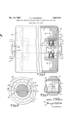
Fig. 1 is a fragmental view, partly in section and showing a conveyor idler roll with my improved inner race locking mechanism applied thereto;
Fig. 2 is a detail sectional view taken generally along line IIII of Fig. 1; and,
Fig. 3 is a fragmental side elevational view of one of the seats with a ball in place therein and held therein by a gob of lubricant or the like.
Referring now to the drawings for a better under- Patented Dec. 14, 1954 ICC standing of my invention I show the same in association wlth an idler roll 10 whichl may be a more or less standard idler roll such as is used for conveyor belts and the like. As is understood, the roll itself comprises an outer cylindrical shell 11. Pressed into the shell are heads 11a. The heads 11a are provided with bores 12 adapted to receive the -outer race 13 of an anti-friction bearing. Ordinarily, the outer race of the bearing is pressed firmly into the bore 12 and the bore may be provided at its inner end with a shoulder 14 forming a stop for the outer race of the bearing. The bearing also comprises the usual inner race 16 and a row of steel balls 17. Likewise, the bearing may carry grease seals indicated at 18, customarily in the form of discs of flexible material such as rubber. The supporting shaft 19 may be grooved as at 20 and the recess or bore 12 may be grooved at 21. Locking rings 22 and 23 fit in the respective grooves 20 and 21 and hold the bearin as a whole in place. v The shaft 19 may be provided with oppositely disposed i vertically extending slots 24 and 26 which are adapted to fit in a suitable slot provided in a mounting bracket 27. The entire roll thus is supported from the shaft 19 and the shaft is held against rotation by means of the slots 24 and 26 fitting into a socket in the bracket 27.
The idler roll described above is substantially standard arrangement for such devices. My invention consists in providing the shaft 19 with oppositely disposed, vertically extending grooves 28 and 29. The grooves 28 and 29 aredisposed relative to the inner race 16 of the bearing so that the race overlies the grooves in the position in the vertical grooves.
manner shown. In the grooves 28 and 29 I place small steel balls 31 and 32. The balls are of a diameter a few thousandths of an inch less than the depth of the grooves 28 and 29 for a reason later to appear.
- kBy reference to Fig. 3 I show one means of holding the balls 31 or 32 in their respective grooves while `the inner race 16 is being pressed onto the shaft. I use a small gob or quantity of paste-like lubricant 33 which is tacky enough to hold the ball for a limited time in I apply a small quantity of such lubricant approximately in the longitudinal center of the grooves l28 or 29 and stick the balls 31 and'32 therein. I am then enabled to insert the shaft 19 into the bore of the inner race 16. f
I preferably employ a substance 33 which melts at a temperature in the neighborhood of from F. to about F. In the manufacture of idler rolls it is customary to paint certain portions thereof and to dry this paint by placing the entire assembly in an oven or by running it under a bank of infra-red lamps. During the process of drying the paint, the lubricant 33 melts and frees the balls 31 and 32, permitting them to fall by gravity into operating position as will be presently explained.
With the balls 31 and 32 assembled in their respective grooves it will be apparent that in the event the inner race 16 of the bearingl tends to rotate in the direction of arrow 34, the ball 32 wedges between the bottom of its groove 29 and the inner surface of the bore of the inner race 16. This action effectively locks the race 16 against rotation relative to the shaft 19. At that same time, the opposite ball 31 is inoperative to prevent rotation of the inner race 16 when the inner race rotates in the direction of arrow 34, but is effective to similarly lock the inner race in the event the same rotates in the direction opposite that indicated by the arrow 34. Therefore, with my improved mechanism I assure that the inner race 16 remains stationary relative to the axle 19 regardless of the direction in which the roll 10 is driven, which direction determines the direction in which the inner race 16 rotates or tends to rotate.
In order that the relative sizes of the grooves, shaft and balls may be understood, and not by way of limitation, I cite the following example of mechanism which is operative for the purpose intended herein:
I have applied my invention to an idler roll for conveyors in which the shaft 19 was approximately 3A of an inch in diameter. In this instance the maximum depth of the grooves as measured along line 36 was made equal to the diameter of the balls to be used plus A-iooo of an inch. The balls selected were ygg inch in diameter, being steel balls such as are commonly used in anti-friction bearings. With balls of the diameter just mentioned in place in grooves of the maximum depth just mentioned, the wedging angle between the balls and the inner surface of the bore of the inner race is adequate to securely lock the race against rotation during the operation of the idler.
A further advantage in my invention lies in the fact that after the rolls are fabricated and painted they are given a final testing to assure that they are free running. A skilled operator can tell, merely by rotating the rolls by hand, whether or not they are free running to the degree required. In view of the fact that one can not see the inner race after the roll is assembled it is important to know that the inner race is standing still so that the operators test indicates that the actual free running of the roll results from the proper functioning of the anti-friction bearings and is not affected in any wise by rotation of the inner race relative to the shaft 19.
In actual practice I have found that my invention is satisfactory in every way and that it is simple and economical of construction. Obviously, if the roll is to operate in a single direction it is apparent that one of the grooves and its associated ball could be omitted, the one employed being placed on the side of the shaft adjacent that part of the inner race which tends to move downwardly.
While I have shown my invention in but one form, it will be obvious to those skilled in the art that it is not so limited but is suceptible of various changes and modications without departing from the spirit thereof, and I desire, therefore, that only such limitations shall be placed thereupon as are specifically set forth in the appended claims.
What I claim is:
1 The combination with a horizontally disposed substantially round stationary shaft and an anti-friction bearing having inner and outer races wherein the inner race is mounted about the shaft for rotation in a given direction, of a vertically disposed groove in the side of the shaft over which the inner race lits, said groove being located on` the side of said shaft adjacent a portion of the race that moves downwardly when the inner race rotates in said given direction, and a gravity actuated ball in said groove of a diameter to move freely in said groove and wedge between the bottom of the groove and the inner surface of the inner race upon rotation of the latter in said given direction.
2. For use in supporting an anti-friction bearing and holding the inner race thereof against rotation in response to rotation of the outer race thereof, a non-rotatable substantially horizontally disposed round shaft on which the inner race is rotatably mounted, a groove in a side of the shaft having a substantially vertically disposed bottom, said inner race overlying the groove, and a gravity actuated ball in said groove of a diameter less than the maximum depth of the groove and of a size to wedge between the bottom of the groove and the adjacent inner surface of the inner race.
3. In combination, an antifriction bearing having inner and outer races, a xedly mounted horizontal substantially round shaft, the inner race of the bearing fitting rotatably about the shaft, there being a vertical groove in the shaft encircled by the inner race and disposed adjacent the downward moving inner surface of the inner race when the same rotates in a given direction, and a gravity actuated ball in the groove of a diameter to move freely in said groove and to wedge between the bottom of the groove and the inner race upon rotation of the latter in said given direction.
4. In combination, a horizontally disposed non-rotatable substantially round shaft, there being substan tially diametrically opposed vertical grooves in the shaft, an anti-friction bearing having an inner race fitting snugly and rotatably about the shaft over said grooves, and gravity actuated balls in said grooves of a diameter for one of the same to wedge between the bottom of its respective groove and the adjacent inner surface of the inner race when the inner race rotates in one direction on the shaft and for the other ball to similarly wedge upon opposite rotation of the inner race.
References Cited in the le of this patent UNITED STATES PATENTS Number Name Date 382,637 Curtis May 8, 1888 422,025 MacDonald Feb. 25, 1890 691,548 Johnson Ian. 2l, 1902 1,400,014 Barber u.. Dec. 13, 1921 1,588,993 Rahn June 15, 1926 1,788,891 Runge Jan. 13, 1931 1,943,998 Adams Ian. 16, 1934 2,581,173 Crankshaw Ian. l, 1952 2,584,256 Brown Feb. 5, 1952
Priority Applications (1)
| Application Number | Priority Date | Filing Date | Title |
|---|---|---|---|
| US247891A US2697016A (en) | 1951-09-22 | 1951-09-22 | Means for securing bearing races to shafts and the like |
Applications Claiming Priority (1)
| Application Number | Priority Date | Filing Date | Title |
|---|---|---|---|
| US247891A US2697016A (en) | 1951-09-22 | 1951-09-22 | Means for securing bearing races to shafts and the like |
Publications (1)
| Publication Number | Publication Date |
|---|---|
| US2697016A true US2697016A (en) | 1954-12-14 |
Family
ID=22936808
Family Applications (1)
| Application Number | Title | Priority Date | Filing Date |
|---|---|---|---|
| US247891A Expired - Lifetime US2697016A (en) | 1951-09-22 | 1951-09-22 | Means for securing bearing races to shafts and the like |
Country Status (1)
| Country | Link |
|---|---|
| US (1) | US2697016A (en) |
Cited By (8)
| Publication number | Priority date | Publication date | Assignee | Title |
|---|---|---|---|---|
| US2796269A (en) * | 1956-03-01 | 1957-06-18 | Lester K Watson | Weight assembly and locking clutch collar |
| US2881629A (en) * | 1955-07-11 | 1959-04-14 | American Metal Prod | Driving gears and shaft supported in housing |
| US2990224A (en) * | 1955-07-20 | 1961-06-27 | Parkersburg Aetna Corp | Bearing |
| US3381549A (en) * | 1965-01-13 | 1968-05-07 | Hirakawa Hirosi | Speed change device |
| US5504409A (en) * | 1994-01-27 | 1996-04-02 | Hr Textron Inc. | Direct drive servovalve having two landed spool power stage |
| US5508575A (en) * | 1994-01-27 | 1996-04-16 | Hr Textron Inc. | Direct drive servovalve having magnetically loaded bearing |
| US5551481A (en) * | 1994-01-27 | 1996-09-03 | Hr Textron Inc. | Method of manufacturing direct drive servovalve and direct drive servovalve resulting therefrom |
| US6000678A (en) * | 1998-10-12 | 1999-12-14 | H.R. Textron Inc. | Motor/spool interface for direct drive servovalve |
Citations (9)
| Publication number | Priority date | Publication date | Assignee | Title |
|---|---|---|---|---|
| US382637A (en) * | 1888-05-08 | Ratchet | ||
| US422025A (en) * | 1890-02-25 | James macdonald | ||
| US691548A (en) * | 1901-07-09 | 1902-01-21 | Christian Johnson | Clutch. |
| US1400014A (en) * | 1920-11-30 | 1921-12-13 | Western Electric Co | Key for fastening gear-wheels, raceways for ball-bearings, and the like to rotatable shafts |
| US1588993A (en) * | 1924-06-23 | 1926-06-15 | Marlin Rockwell Corp | Ball bearing |
| US1788891A (en) * | 1929-06-24 | 1931-01-13 | Skayef Ball Bearing Company | Means for securing antifriction bearings on shafts |
| US1943998A (en) * | 1930-08-13 | 1934-01-16 | Mathews Conveyer Co | Conveyer |
| US2581173A (en) * | 1951-01-26 | 1952-01-01 | Gen Electric | Bearing assembly |
| US2584256A (en) * | 1949-04-06 | 1952-02-05 | Oren G Brown | Roller type ratchet structure |
-
1951
- 1951-09-22 US US247891A patent/US2697016A/en not_active Expired - Lifetime
Patent Citations (9)
| Publication number | Priority date | Publication date | Assignee | Title |
|---|---|---|---|---|
| US382637A (en) * | 1888-05-08 | Ratchet | ||
| US422025A (en) * | 1890-02-25 | James macdonald | ||
| US691548A (en) * | 1901-07-09 | 1902-01-21 | Christian Johnson | Clutch. |
| US1400014A (en) * | 1920-11-30 | 1921-12-13 | Western Electric Co | Key for fastening gear-wheels, raceways for ball-bearings, and the like to rotatable shafts |
| US1588993A (en) * | 1924-06-23 | 1926-06-15 | Marlin Rockwell Corp | Ball bearing |
| US1788891A (en) * | 1929-06-24 | 1931-01-13 | Skayef Ball Bearing Company | Means for securing antifriction bearings on shafts |
| US1943998A (en) * | 1930-08-13 | 1934-01-16 | Mathews Conveyer Co | Conveyer |
| US2584256A (en) * | 1949-04-06 | 1952-02-05 | Oren G Brown | Roller type ratchet structure |
| US2581173A (en) * | 1951-01-26 | 1952-01-01 | Gen Electric | Bearing assembly |
Cited By (8)
| Publication number | Priority date | Publication date | Assignee | Title |
|---|---|---|---|---|
| US2881629A (en) * | 1955-07-11 | 1959-04-14 | American Metal Prod | Driving gears and shaft supported in housing |
| US2990224A (en) * | 1955-07-20 | 1961-06-27 | Parkersburg Aetna Corp | Bearing |
| US2796269A (en) * | 1956-03-01 | 1957-06-18 | Lester K Watson | Weight assembly and locking clutch collar |
| US3381549A (en) * | 1965-01-13 | 1968-05-07 | Hirakawa Hirosi | Speed change device |
| US5504409A (en) * | 1994-01-27 | 1996-04-02 | Hr Textron Inc. | Direct drive servovalve having two landed spool power stage |
| US5508575A (en) * | 1994-01-27 | 1996-04-16 | Hr Textron Inc. | Direct drive servovalve having magnetically loaded bearing |
| US5551481A (en) * | 1994-01-27 | 1996-09-03 | Hr Textron Inc. | Method of manufacturing direct drive servovalve and direct drive servovalve resulting therefrom |
| US6000678A (en) * | 1998-10-12 | 1999-12-14 | H.R. Textron Inc. | Motor/spool interface for direct drive servovalve |
Similar Documents
| Publication | Publication Date | Title |
|---|---|---|
| CA2661822C (en) | Idler roll bearing assembly and method of making | |
| US2697016A (en) | Means for securing bearing races to shafts and the like | |
| FR2045063A5 (en) | ||
| US4606659A (en) | Bearing and stub shaft assembly | |
| US1722489A (en) | Means for retaining lubricant and excluding dust | |
| US2150796A (en) | Top roll | |
| US5399026A (en) | Bearing with lubricating ring for providing supplemental lubrication | |
| ATE134252T1 (en) | BEARING CONSTRUCTION WITH A MULTI-PIECE RACE | |
| GB1437838A (en) | Bearing lubrication system for bowed rolls | |
| US4085980A (en) | Toothed rolling contact devices | |
| US4830179A (en) | Idler rollers for belt conveyors | |
| US3381798A (en) | Roller flight conveyor | |
| US2622946A (en) | Retaining means for idler units | |
| US2736617A (en) | Roller bearing | |
| US3070410A (en) | Grease check valve | |
| US3929391A (en) | Conveyor belt idler rollers | |
| US2012256A (en) | Bearing | |
| US2155657A (en) | Thrust bearing | |
| GB1190288A (en) | Improved Rotatable Deck Fitting | |
| US1737036A (en) | Lubricating means for conveyer rollers | |
| GB948480A (en) | Improvements in bearings | |
| US2010752A (en) | Bearing for coffee roasters | |
| US1837480A (en) | Construction for rollers and the like | |
| US2675281A (en) | Self-aligning bearing | |
| US2652295A (en) | Rotary bearing construction |