US2676206A - Computation and display of correlation - Google Patents
Computation and display of correlation Download PDFInfo
- Publication number
- US2676206A US2676206A US260172A US26017251A US2676206A US 2676206 A US2676206 A US 2676206A US 260172 A US260172 A US 260172A US 26017251 A US26017251 A US 26017251A US 2676206 A US2676206 A US 2676206A
- Authority
- US
- United States
- Prior art keywords
- signal
- time
- multiplier
- medium
- lag
- Prior art date
- Legal status (The legal status is an assumption and is not a legal conclusion. Google has not performed a legal analysis and makes no representation as to the accuracy of the status listed.)
- Expired - Lifetime
Links
Images

Classifications
-
- G—PHYSICS
- G06—COMPUTING OR CALCULATING; COUNTING
- G06G—ANALOGUE COMPUTERS
- G06G7/00—Devices in which the computing operation is performed by varying electric or magnetic quantities
- G06G7/12—Arrangements for performing computing operations, e.g. operational amplifiers specially adapted therefor
- G06G7/19—Arrangements for performing computing operations, e.g. operational amplifiers specially adapted therefor for forming integrals of products, e.g. Fourier integrals, Laplace integrals or correlation integrals; for analysis or synthesis of functions using orthogonal functions
- G06G7/1928—Arrangements for performing computing operations, e.g. operational amplifiers specially adapted therefor for forming integrals of products, e.g. Fourier integrals, Laplace integrals or correlation integrals; for analysis or synthesis of functions using orthogonal functions for forming correlation integrals; for forming convolution integrals
-
- G—PHYSICS
- G10—MUSICAL INSTRUMENTS; ACOUSTICS
- G10L—SPEECH ANALYSIS TECHNIQUES OR SPEECH SYNTHESIS; SPEECH RECOGNITION; SPEECH OR VOICE PROCESSING TECHNIQUES; SPEECH OR AUDIO CODING OR DECODING
- G10L25/00—Speech or voice analysis techniques not restricted to a single one of groups G10L15/00 - G10L21/00
Definitions
- This invention relates-tosignal analysis and particularly to the analysis of time-varying signals by way of correlation techniques.
- a running record of the signal to be analyzed is made, for example in the formv of a spacevariant signal on a magnetizable tape, and thereafter, and for contemporaneous analysis immediately thereafter, a reproducing device scans a small segment of this record to provide a new time-variant signal which is related in known fashion to the original one.
- This new signal is appliedto a delay device having a multiplicity of taps. These taps are connected in succession to one input point of a multiplier, while the undelayed signal is connected to the other input point of themultiplier.
- the output derived from each tap of the delay device is of the form )(11-1'), where 1- has a different value for each tap.
- the multiplier forms a, product fit) '(t-'r) for each successive value of lag 'r.
- the product is then integrated over an appropriate time and the result is thus in accordance-with Equation 2.
- the reproducer scans the selected segment of the original record repeatedly, there occur instants in the; course of each scan in which the signal-resulting from the beginning of one scan; is stored at the head end of the delay device while the signal resulting from the concluding part of theprior scan is still stored in the tail end of the delay device. Multiplication of these signals, one by the other, would evidently give an erroneous result. Therefore, in accordance with a further feature of the invention, provision is made to avoid errors of this character by sampling the outputs of the successive delay device taps at those instants, and only at those instants, during which the signal stored in the delay device,1is from end to end thereof, due to a single scan of the recorded recordsegment by the reproducer.
- the quantity so computed or generated is applied to the stylus or other current-sensitive element of a suitable recorder which in itself may be of a construction well known in the art of facsimile transmission and which isadapted to; translate the computed quantity into. amark of variable intensity on a suitable medium which-is steadily advanced past the recorder in a time coordinate, while a suitable mechanism iselnployed to move the stylus laterally over a medium in coordination with the changes in lag which are employed. as a feature of the analysis. There results a plot of the correlation of the two signals considered, or the autocorrelation of the one signal considered, as the case may be, as a variation of intensity in lag-time coordinates. In other words, there results a three-dimensional. intensity-lag-time plot.
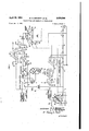
- Fig. l is a schematic circuit diagram embodying the invention.
- Fig. 2 is an explanatory diagram illustrating the need for-a certain feature of the invention.
- Fig. 3 is a representation of the autocorrelation function of a sine wave-as computed and plotted by the apparatus of Fig. 1.
- the signal to be analyzed, and, originating for example in a microphone l is first translated by'a recording device ,2 into a space-variant signal onto a lineal record, for example a magnetizable tape 3.
- a lineal record for example a magnetizable tape 3.
- a small segment of this tape passes around a semicircular track 4 where it israpidly and repeatedly scanned, e. g., sixty times persecond. by one member or the other of a pair of magnetic reproducers 5, which are connected, in series or in, parallel, to a conductor 6.
- the latter is connected, e.
- a delay device such as an electromagnetic. delay" line 8.
- the latter' may comprise for example, 240 similarsections having 120 evenly spaced taps i. e., one located at every other section.
- Theline 8 may'beterminated in well-known fashion forno reflection by a load 9. In terms of propagation time-along the delay line 8 thespacing'between each tap and the next one may be 20 microseconds; the total delay for all 240 sections beingthus. 2.4 milliseconds.
- Each of these taps is connected to.'a segment of a commutator I2 whose wiperarm l3 sweeps over them in succession, making .afull revolution in 2 seconds, during which. period the reproducers have accomplished 120 scans,,one for each tap' of' thecdelayxline: 8.
- A. commondrlve ll assures the requiredsynchronism.
- A' conductor l4 connectedto the. wiper. arm. l3.. thus carries a sequence of samples of theisignalieach of which lags the other by 20 microseconds. These samples are passed by way of a double-triode gate and an amplifier IE to one input point of a multiplier for example across the horizontal diagonal of a bridge multiplier ll whose midpoint is effectively grounded.
- this reference signal is applied by way of a conductor IE to. the other input point of this multiplier 11, forexample, the terminals of its vertical diagonal.
- this reference signal may be the output of the reproducers 5 as it appears on the conductor 1.
- the reference signal may be. derived from an independentreference signal source 9.
- a manual switch is provided. for; the. shift.
- the output which appears between the midpoint of. the. vertical diagonal of such a bridge multiplierl1 and ground is. proportional to the productof the, two input signals. Alter. level adjustment, if desired, byanamplifier 2
- gating pulses establishes a low resistance path from thezcath- Ode follower tube 25 to apower amplifier 3
- the multivibrator or other timing pulse source must evidently be synchronized'and phased with the movementof the commutator wiper arm.
- The'integrating condenser 23, for correct operation, should be discharged at the conclusion of each of its operations and for this purpose it is connected by way of. a relay contact 33 to ground each time agating, pulse is applied to the relay winding 34.
- gating pulses may be derived from the sample-gating multivibrator'30 and slightly delayed by an auxiliary multivibrator 35'with respect to the-sample gating pulses.
- FIG. 2 shows the situation whichholdszwhenone reproducer head '5 has just concluded its scan of the record segment supported by the'track 4 and the other has just entered upon the recorded segment and has commenced the next scan.
- a construction of the commutator segment places exceedingly severe demands on the precision with which it is fabricated and, therefore, in accordance witha further feature of the invention, illustrated in. Fig. 1,.
- the stringency of these requirements is relieved by the interposition. of a gate", e, g., the triode gate i5, between theoutputconductor M of the commutator wiper arm 13 and the multiplier l'l.v
- a buffer 281bthis triodegate. is actuated-sixty times per second and for a period of 14.3 milliseconds on each occasion by the output of a single trip multiyibrator 38 which is. tripped by a pulse derived, for example, from the. assage of either of two supplementary contacts 31: mounted on. the arm recorder whose. construction may be similar to s.
- One suitable recorder comprises. an. endless belt 43: of conducting material bearing three styli: 4 5. It is advanced by pulleys 85 driven: by the commondriveal i in such fashion that each stylus. 44 moves from one margin of a strip. ofsensitive paper :46,-such as Western Union Teledeltos paper, to the: other margin m the same time, e. g, two seconds, as "is occupied by the commutator wiper i3 in accomplishing one full commutator revolution and by the reproducer heads 5 in making a number of scans of the record segment equal to the number of segments. of the commutator i2; As each one of the styl'i 46 leaves the paper strip it, an-
- said product over a time of interest to form: an integral, means for successively increasing the lag 1' to each of a succession of dirierentvaleres, means.itoriiepeating said operations of multiplication and inte-- gration for each such value of 7', an impressionsensi-tive medium, means for continuously advancing said: medium in proportion. to: time: in a longitudinal directionsarecordingelement, means formoving: said element. acrosssaid medium once for each: full passage of the: lag T through all of its values, and. means for applying. said integral to. said element to form. impressions thereon of density rel'atedtothe autocorrelation function of said original signal and at points of said medium related to time and to lag.
- Apparatus for computing the. correlation functionof two signals: flft). and i202) and for displaying. the same, concurrently with the generation of. said; signals, as a function of time and of lag which. comprises means for delaying said second. signal :by acontrollably variable. amount 1, to form.
- a lagged signal f2 means for multiplying the lagged second signal by the first signal so) to form a product, means for integrating said product over a time'of' interest to form-an integral, means for successively increasing the lag 1 to: each of a succession of different values, means for repeating said operations of multiplication and integration for each such value of 1-, an impression-sensitive medium, means for continuous- 1y advancingrsai'd medium inpro'portion to time in a longitudinal direction, a recording element, means for moving said: element across said medium once for each full passage of the lag 1- through all of its values, and means for applying said integral to said element to form impressions thereon of density related to the correlation'function of said original signals and at points of said medium related: to time and to lag.
- Apparatus for computing the correlation function of two signals hit) and fzitl and for displaying the same, concurrently with the generation of said signal, as a function of time and of lag which comprises means for generating successivevalue's of alag 1', means for generating the product of""f'1('fi) jz t-) for each-such valueof l '1', means for integrating each of said products over a time of interest to form a derived signal, an impression-sensitive medium, means for regularly advancing said medium in proportion to time in a longitudinal direction, a recording element, means for moving said element across said medium once for each full passag of the lag 7 through all of its values, and means for applyin said derived signal to said element to form impressions thereon of density related to the correlation function of said original signals and at points of said medium related to time and to lag.
- Apparatus for computing the autocorrelation of a signal f(t) and for displaying the same, concurrently with the generation of said signal, as a function of time and of lag which comprises means for generating successive values of a lag 1-, means for generating a product f(t) -,f(t1) for each such value of 1-, means for integrating each of said products over a time of interest to form a derived signal, an impression-sensitive medium, means [or regularly advancing said medium in proportion to time in a longitudinal direction, a recording element, means for moving said element across said medium once for each full passage of the lag 1 through all of its values, and means for applying said derived signal to said element to form impressions thereon of density related to the autocorrelation function of said original signal and at points of said medium related to time and to lag.
- Apparatus for computing the autocorrelation function of a signal and for displaying the same as a function of time and of lag which comprises means for first forming a space-variant record counterpart of said signal at a first speed, means for repeatedly scanning a short segment of said space-variant record at a higher speed to provide a time-variant signal whose frequencies are increased as compared with the frequencies of the original signal in the ratio of the scanning speed to the recording speed, a multiplier having two input points and an output point, one input point being connected directly to said scanning means,
- variable time delay means comprising a delay device having an input point and a plurality of taps, said last-named input point being connected directly to said scanning means, means for establishing a connection from one of said taps to the second input point of said multiplier during each passage of said scanning means over said record segment, means for regularly advancing the tap from which said connection is established, one tap for each passage of said scanning means over said record segment, whereby said scanning means is connected to the first of said multiplier input points by way of a path of invariant length and to the second of said multiplier input points by a path including a length of said delay device from the input point thereof to the tap to which connection is currently made, means for integrating the multiplier output over the period of each passage of said scanning means over said record segment, means for regularly sampling the output of said multiplier once for each passage of said scanning means over said record segment, an impression receiving medium having a length dimension and a width dimension, means for continuously advancing said medium in its length dimension in proportion to time, a stylus movable in the width dimension of said
- Apparatus as defined in claim 5 wherein the means for establishing a connection to the second input point of the multiplier from a tap of the delay device comprises a gate, and means for energizing said gate to establish said connection only during periods when the signal stored in said delay device is derived from a single scan of said space-variant record by said scanning means.
- apparatus for computing the correlation function of two signals and for displaying the same as a function of time and of lag which comprises a multiplier having two input points and an output point, one input point being connected directly to the source of one of said signals, variable time delay means comprising a delay device having an input point and a plurality of taps, said last-named input point being connected directly to the source of the other of said signals, means for establishing a connection from one of said taps to the second input point of said multiplier, means for regularly advancing the tap from which said connection is established, whereby the source of the one signal is connected to the first of said multiplier input points by way of a path of invariant length and the source of the other signal is connected to the second of said multiplier input points by a path including a length of said delay device from the input point thereof to the tap to which connection is currently made, means for integrating the multiplier output over a period of interest to form an integral, and means for displaying each successive value of said integral as intensity in a field
- apparatus for computing the autocorrelation function. of a signal of said source and for displaying the same as a function of time and of lag which comprises means for first breaking said signal into a plurality of successive short segments, a multiplier having two input points and an output point, means for applying said short signal segments to one of said input points, variable time delay means comprising a delay device having an input pointand a plurality of taps, means for applying said short signal segments to said last-named input point, means for successively establishing connections from all of said taps to the second input point of said multiplier during each of said successive signal segments, whereby said signal segments are applied to the first of said multiplier input points by way of a path of invariant length and to the second of said multiplier input points by a path including a length of said delay device from the input point thereof to the tap to which connection is currently made, means for integrating the multiplier output over the period of each signal segment to form an integral, and means for displaying each successive value of said integral as intensity in
- paratus for computing the autocorrelation function of a signal of said source and for displaying the same as a function of time and of la which comprises means for first breaking said signal into a plurality of successive short segments, a multiplier having two input points and an output point, one input point being connected directly to said source, variable time delay means comprising a delay device having an input point and a plurality of taps, said last-named input point bein connected directly to said source, means for successively establishing connections from all of said taps to the second input point of said multiplier duringeach of said successive signal segments, whereby said source is connected to the first of said multiplier input points by way of a path of invariant length and to the second of said multiplier input points by a path including a length of said delay device from the input point thereof to the tap to which connection is currently made, means for integrating the multiplier output over the period of each signal segment, an impression receiving medium having a length dimension and a width dimension, means for continuously advancin said medium in its length dimension in proportion
Landscapes
- Engineering & Computer Science (AREA)
- Physics & Mathematics (AREA)
- Mathematical Physics (AREA)
- Theoretical Computer Science (AREA)
- Software Systems (AREA)
- General Physics & Mathematics (AREA)
- Computer Hardware Design (AREA)
- Computational Linguistics (AREA)
- Signal Processing (AREA)
- Health & Medical Sciences (AREA)
- Audiology, Speech & Language Pathology (AREA)
- Human Computer Interaction (AREA)
- Acoustics & Sound (AREA)
- Multimedia (AREA)
- Measurement Of Mechanical Vibrations Or Ultrasonic Waves (AREA)
Description
. 2 Sheets-Sheet l w. R. BENNETT ETAL COMPUTATION AND DISPLAY OF CORRELATION April 20,. 1954 Fileql Dec. 6, 1951 w n mw mm Am a ATTORNEY m R. BENNETT INVENTORS L'. c. PETERSON Filed Dec. 6, 1951 April 1954 w. R. BENNEAI'T ETAL v2,676,206
COMPUTATION AND DISPLAY OF CORRELATION I 2 Sheets-Sheet 2 MMMW/WVWMWEJ M 1 FIG. 3
TIME, t
' nz R. BENNETT INVENTORS' L; c, PETERSON ATTORNEV Patented Apr. 20, 1954 COMPUTATION AND DISPLAY OF CORRELATION William R. Bennett, Summit, and Liss 0. Peterson, Ghatham, N. J assignors to Bell Telephone Laboratories, Incorporated, New York, N. Y., a
corporation of New York Application December 6, 1951, Serial No. 260,172
This invention relates-tosignal analysis and particularly to the analysis of time-varying signals by way of correlation techniques.
It is well known to analyze a signal which is a function of time into its several frequency components, determine the energy in each-of these components and display the result as a variation of intensity on a' plot whose rectangular coordinates are frequency and time. Such apparatus or spectrograph, as it has been termed, and the analyses obtained therewith are shown for example in An 8000- cycle sound spectrograph by Otto Gruenz, published in the Bell Laboratories Record for June 1951, vol. 29, page 256. While this apparatus requires that a complete record be made of the signal to be analyzed before the analysis is started, means are also known by which analyses of this character may be carried out substantially contemporaneously with the generationor reception of the signal. -When'the information contained in a signal presents itself naturally as a complex of frequencies or when it isthe frequencyof its variouscomponents which are of principal interest, apparatus such as that described in the aforementioned publication serves the purpose.
There exist, however, signals which naturally appear in the form of a pulse or a sequence'of pulses, and there exist circumstances under which-the time relations of such phenomena are ticular, the cross correlation m of two signals f1(t) and fad), is given, for any particular'value of 1, by r towni -on -1) Autocorrelation (p11 is similar, with the sole difference thatone signal is a delayed versioiro the other, thus mus-0 Inthese expressions; the integration is taken over a range of the timerxtending from 9 Claims. (Cl. 179-1) the origin of coordinates being taken at the center of the range.
Theoretical aspects of correlation analysis are described for example in Correlation function analysis by L. G. Kraft, published in the Journal of the Acoustical Society of America for November 1950, vol. 22, page 762. Rudimentary apparatus for the delayed computation of autocorrelation, based on the preliminary formation of a complete record of the signal, is shown in an article by K. N. Stevens published at page '169 ,of the same journal. I Accordingly, primary "objects of the invention are to perform a correlation analysis on an incoming signal and to perform it substantially instantaneously, i. e., concurrently with the generation or reception of the signal. To this end a running record of the signal to be analyzed is made, for example in the formv of a spacevariant signal on a magnetizable tape, and thereafter, and for contemporaneous analysis immediately thereafter, a reproducing device scans a small segment of this record to provide a new time-variant signal which is related in known fashion to the original one. This new signal is appliedto a delay device having a multiplicity of taps. These taps are connected in succession to one input point of a multiplier, while the undelayed signal is connected to the other input point of themultiplier. Inasmuch as a portion of the scanned segment of the derived signal is at every instant stored' in the delay device, and as the derived signal is in the form f(t), then the output derived from each tap of the delay device is of the form )(11-1'), where 1- has a different value for each tap. Thus the multiplier forms a, product fit) '(t-'r) for each successive value of lag 'r. The product is then integrated over an appropriate time and the result is thus in accordance-with Equation 2.
Because the reproducer scans the selected segment of the original record repeatedly, there occur instants in the; course of each scan in which the signal-resulting from the beginning of one scan; is stored at the head end of the delay device while the signal resulting from the concluding part of theprior scan is still stored in the tail end of the delay device. Multiplication of these signals, one by the other, would evidently give an erroneous result. Therefore, in accordance with a further feature of the invention, provision is made to avoid errors of this character by sampling the outputs of the successive delay device taps at those instants, and only at those instants, during which the signal stored in the delay device,1is from end to end thereof, due to a single scan of the recorded recordsegment by the reproducer.
In further accordance with the invention, the quantity so computed or generated is applied to the stylus or other current-sensitive element of a suitable recorder which in itself may be of a construction well known in the art of facsimile transmission and which isadapted to; translate the computed quantity into. amark of variable intensity on a suitable medium which-is steadily advanced past the recorder in a time coordinate, while a suitable mechanism iselnployed to move the stylus laterally over a medium in coordination with the changes in lag which are employed. as a feature of the analysis. There results a plot of the correlation of the two signals considered, or the autocorrelation of the one signal considered, as the case may be, as a variation of intensity in lag-time coordinates. In other words, there results a three-dimensional. intensity-lag-time plot.
The invention will be fully apprehended. from the following detailed description ofapreferred embodiment thereof, taken in connection with the appended draWings in which:
Fig. l is a schematic circuit diagram embodying the invention;
Fig. 2 is an explanatory diagram illustrating the need for-a certain feature of the invention; and
Fig. 3 is a representation of the autocorrelation function of a sine wave-as computed and plotted by the apparatus of Fig. 1.
In the description which follows, principal emphasis is laid on the determination and display of the autocorrelation functionof a single signal ecause this is the'problem of main practical interest. However, by merely throwing a switch, a reference signal is substituted for the undelayed signal, in which case the apparatus computes and displays the cross-correlation function of two signals.
Referring now to the drawings, the signal to be analyzed, and, originating for example in a microphone l is first translated by'a recording device ,2 into a space-variant signal onto a lineal record, for example a magnetizable tape 3. A small segment of this tape passes around a semicircular track 4 where it israpidly and repeatedly scanned, e. g., sixty times persecond. by one member or the other of a pair of magnetic reproducers 5, which are connected, in series or in, parallel, to a conductor 6. The latter is connected, e. g., by a rotary connector or slip ring, not shown, to an output conductor '1; The timevariantsignal which results from this-operation is now applied by wayof the output conductor 7 to the-input end of a delay device: such as an electromagnetic. delay" line 8. The latter'may comprise for example, 240 similarsections having 120 evenly spaced taps i. e., one located at every other section. Theline 8 may'beterminated in well-known fashion forno reflection by a load 9. In terms of propagation time-along the delay line 8 thespacing'between each tap and the next one may be 20 microseconds; the total delay for all 240 sections beingthus. 2.4 milliseconds.
Each of these taps is connected to.'a segment of a commutator I2 whose wiperarm l3 sweeps over them in succession, making .afull revolution in 2 seconds, during which. period the reproducers have accomplished 120 scans,,one for each tap' of' thecdelayxline: 8. A. commondrlve ll assures the requiredsynchronism. A' conductor l4 connectedto the. wiper. arm. l3.. thus carries a sequence of samples of theisignalieach of which lags the other by 20 microseconds. These samples are passed by way of a double-triode gate and an amplifier IE to one input point of a multiplier for example across the horizontal diagonal of a bridge multiplier ll whose midpoint is effectively grounded. At the same time a reference signal is applied by way of a conductor IE to. the other input point of this multiplier 11, forexample, the terminals of its vertical diagonal. In the caseof autocorrelation analysis, this reference signal may be the output of the reproducers 5 as it appears on the conductor 1. In the case of cross-correlation analysis, the reference signal may be. derived from an independentreference signal source 9. A manual switch is provided. for; the. shift. As i well known, the output which appears between the midpoint of. the. vertical diagonal of such a bridge multiplierl1 and ground is. proportional to the productof the, two input signals. Alter. level adjustment, if desired, byanamplifier 2|, this product is now integrated over a period equal. to and coincident with the interval during whichthe wiper arm. [3 is in electrical.contactwith one segment of the commutator 12. The: combination. of a resistor 22 and a condenser 2-3, whose time constant is about ten times this interval, or 140 milliseconds in the. illustrative embodiment, serves the purpose. The integral thus formed is now applied to the grid of. a cathode follower tube 25 whose cathodealoadlmpedance 26 is connected to a double triode. gatell whose grids are supplied by wayof a buffer 28a with gating pulses 29 derived from a timingpulse-source such as a multivibrator. 30. Each. of. these: gating pulses establishes a low resistance path from thezcath- Ode follower tube 25 to apower amplifier 3| when and only when a gating pulse appears, thus applying; to a condenser 32 a: charge-proportional to the charge-appearing on theintegrating condenser 23 at the end of each. contact interval of the wiper l3 witha. commutator bar. For this purpose the multivibrator or other timing pulse source must evidently be synchronized'and phased with the movementof the commutator wiper arm.
The'integrating condenser 23, for correct operation, should be discharged at the conclusion of each of its operations and for this purpose it is connected by way of. a relay contact 33 to ground each time agating, pulse is applied to the relay winding 34. Such gating pulses may be derived from the sample-gating multivibrator'30 and slightly delayed by an auxiliary multivibrator 35'with respect to the-sample gating pulses.
Coming now to the feature by which incorrect multiplications are avoided, Fig. 2, from which many circuit elements not germane to the particular problem have been. omitted, shows the situation whichholdszwhenone reproducer head '5 has just concluded its scan of the record segment supported by the'track 4 and the other has just entered upon the recorded segment and has commenced the next scan. The signal most recently picked up by the right-hand reproduce! head, which originated at an earlier time n, is stored in the tail end of the delay line 8 as j(t1), while the signal being picked up by the left-hand reproducer head, which originated at a later time t2, is being stored in the head end of the delay line as fltz) If, under such conditions, the output of one of the far end taps of the delay line 8 weretobe-multiplied bythe-nndelayed signal the result would be the impropernproduct m2) coir-T).
Ideally this. situation can be avoided by ad-' jnsting thelength of each. of the. segments of the commutator [2 in such fashion that the duration of contact between the wiperyarm. ['3' and any one segment coincides exactly with the time interval in which the delay line 8 is completely filled by the output of asingle sweep of one of the reproducer heads:- 5 across the recordedisignal segment. In the illustrative embodiment shown, an. interval of 2.4 milliseconds, equal to thetotal delay of the. whole.- delay line: 8, elapses between the beginning of a sweep of one reproducer head 5 and the time at which allxof. the energy stored in the delay line 8 from the previous sweep of the other reproducer: head 5 has been completely dissipated in the terminating impedance. 9 at the far end of. the line. By correct adjustment of the length of each commutator segment and of the space between. adjacentsegments thewiper'arm I3 is held out of electrical contact with. any conducting segment of the commutator during this 2.4 millisecond interval. Following each. such blank interval the wiper arm l3 then makes electrical contact: with conducting segment throughout the remaining 1.4.3 milliseconds of the wiper cycle, thesum of; these two intervals. being Such. a construction of the commutator segment places exceedingly severe demands on the precision with which it is fabricated and, therefore, in accordance witha further feature of the invention, illustrated in. Fig. 1,. the stringency of these requirements is relieved by the interposition. of a gate", e, g., the triode gate i5, between theoutputconductor M of the commutator wiper arm 13 and the multiplier l'l.v By way of a buffer 281bthis triodegate. is actuated-sixty times per second and for a period of 14.3 milliseconds on each occasion by the output of a single trip multiyibrator 38 which is. tripped by a pulse derived, for example, from the. assage of either of two supplementary contacts 31: mounted on. the arm recorder whose. construction may be similar to s.
the recorders customarily employed in the art of facsimile transmission. One suitable recorder comprises. an. endless belt 43: of conducting material bearing three styli: 4 5. It is advanced by pulleys 85 driven: by the commondriveal i in such fashion that each stylus. 44 moves from one margin of a strip. ofsensitive paper :46,-such as Western Union Teledeltos paper, to the: other margin m the same time, e. g, two seconds, as "is occupied by the commutator wiper i3 in accomplishing one full commutator revolution and by the reproducer heads 5 in making a number of scans of the record segment equal to the number of segments. of the commutator i2; As each one of the styl'i 46 leaves the paper strip it, an-
other one enters upon it. Meanwhile the record tape tis continuously advanced by the drive ll past the reproducers 5, and the'paper 46 is continuously led by the drive H pastthe stylifl'd and over a roller- 48 "which may tiegrounded.-
Asa result thecurrent entering the. conductive belt 4 3 from the power amplifier 3d traverses the: paper 46 to the. roller '48 in the form ofxa; spark discharge whose intensity is substantially proportional tothat of the output of the amplifier 3.1:, independent. of its sign; i. e., the signal is rectified. in recording; This process forms. a mark on the: paper 4'6 whose density is related to the. quantity computed by the analyzing apparatus, namely the cross-correlation between the recorded signal and the reference." signal, or the autocorrelation of the recorded signal. Each suchmark appears at a part of the paper whose lateral coordinate isiproportional to lag, and whose lengthwise. coordinate is proportional: to. time. Thus a threeedimensional intensity-lagtime pattern is continuously built up. Figs 3 in.- dicates the appearanceof such a pattern for a sine. wave,,the. lag; 7' extending; over four wavelengths.
What is claimedisz.
.1. Apparatus for computing the. autocorrelation. function of asi-gnal f(.t) andtfor displaying. the same, concurrently with the generation 01." said signal, as a functionoftimeand of lag: which comprises means fior' delaying said signal by a. controllably variable amount 1-, to form a lagged signal f-(t-'r), means for multiplying the lagged signal. fit) by the original. signal to form a. product, means for integrating. said product over a time of interest to form: an integral, means for successively increasing the lag 1' to each of a succession of dirierentvaleres, means.itoriiepeating said operations of multiplication and inte-- gration for each such value of 7', an impressionsensi-tive medium, means for continuously advancing said: medium in proportion. to: time: in a longitudinal directionsarecordingelement, means formoving: said element. acrosssaid medium once for each: full passage of the: lag T through all of its values, and. means for applying. said integral to. said element to form. impressions thereon of density rel'atedtothe autocorrelation function of said original signal and at points of said medium related to time and to lag.
2. Apparatus for computing" the. correlation functionof two signals: flft). and i202) and for displaying. the same, concurrently with the generation of. said; signals, as a function of time and of lag which. comprises means for delaying said second. signal :by acontrollably variable. amount 1, to form. a lagged signal f2 (f-T) means for multiplying the lagged second signal by the first signal so) to form a product, means for integrating said product over a time'of' interest to form-an integral, means for successively increasing the lag 1 to: each of a succession of different values, means for repeating said operations of multiplication and integration for each such value of 1-, an impression-sensitive medium, means for continuous- 1y advancingrsai'd medium inpro'portion to time in a longitudinal direction, a recording element, means for moving said: element across said medium once for each full passage of the lag 1- through all of its values, and means for applying said integral to said element to form impressions thereon of density related to the correlation'function of said original signals and at points of said medium related: to time and to lag.
3. Apparatus for computing the correlation function of two signals hit) and fzitl and for displaying the same, concurrently with the generation of said signal, as a function of time and of lag which comprises means for generating successivevalue's of alag 1', means for generating the product of""f'1('fi) jz t-) for each-such valueof l '1', means for integrating each of said products over a time of interest to form a derived signal, an impression-sensitive medium, means for regularly advancing said medium in proportion to time in a longitudinal direction, a recording element, means for moving said element across said medium once for each full passag of the lag 7 through all of its values, and means for applyin said derived signal to said element to form impressions thereon of density related to the correlation function of said original signals and at points of said medium related to time and to lag.
4. Apparatus for computing the autocorrelation of a signal f(t) and for displaying the same, concurrently with the generation of said signal, as a function of time and of lag which comprises means for generating successive values of a lag 1-, means for generating a product f(t) -,f(t1) for each such value of 1-, means for integrating each of said products over a time of interest to form a derived signal, an impression-sensitive medium, means [or regularly advancing said medium in proportion to time in a longitudinal direction, a recording element, means for moving said element across said medium once for each full passage of the lag 1 through all of its values, and means for applying said derived signal to said element to form impressions thereon of density related to the autocorrelation function of said original signal and at points of said medium related to time and to lag.
5. Apparatus for computing the autocorrelation function of a signal and for displaying the same as a function of time and of lag which comprises means for first forming a space-variant record counterpart of said signal at a first speed, means for repeatedly scanning a short segment of said space-variant record at a higher speed to provide a time-variant signal whose frequencies are increased as compared with the frequencies of the original signal in the ratio of the scanning speed to the recording speed, a multiplier having two input points and an output point, one input point being connected directly to said scanning means,
variable time delay means comprising a delay device having an input point and a plurality of taps, said last-named input point being connected directly to said scanning means, means for establishing a connection from one of said taps to the second input point of said multiplier during each passage of said scanning means over said record segment, means for regularly advancing the tap from which said connection is established, one tap for each passage of said scanning means over said record segment, whereby said scanning means is connected to the first of said multiplier input points by way of a path of invariant length and to the second of said multiplier input points by a path including a length of said delay device from the input point thereof to the tap to which connection is currently made, means for integrating the multiplier output over the period of each passage of said scanning means over said record segment, means for regularly sampling the output of said multiplier once for each passage of said scanning means over said record segment, an impression receiving medium having a length dimension and a width dimension, means for continuously advancing said medium in its length dimension in proportion to time, a stylus movable in the width dimension of said medium, means for cyclically moving said stylus across said medium from side to side thereof in its width dimension once for each full cycle of establishment of connections to the several taps of said delay device,
and means for applying the output of said sampling device to said stylus, whereby an impression is formed on said medium whose intensity is proportional to the magnitude of the autocorrelation function of said signal and whose location on said medium is proportional to th time at which, and to the self-displacement for which, said magnitude exists.
6. Apparatus as defined in claim 5 wherein the means for establishing a connection to the second input point of the multiplier from a tap of the delay device comprises a gate, and means for energizing said gate to establish said connection only during periods when the signal stored in said delay device is derived from a single scan of said space-variant record by said scanning means.
7. In combination with two signal sources, apparatus for computing the correlation function of two signals and for displaying the same as a function of time and of lag which comprises a multiplier having two input points and an output point, one input point being connected directly to the source of one of said signals, variable time delay means comprising a delay device having an input point and a plurality of taps, said last-named input point being connected directly to the source of the other of said signals, means for establishing a connection from one of said taps to the second input point of said multiplier, means for regularly advancing the tap from which said connection is established, whereby the source of the one signal is connected to the first of said multiplier input points by way of a path of invariant length and the source of the other signal is connected to the second of said multiplier input points by a path including a length of said delay device from the input point thereof to the tap to which connection is currently made, means for integrating the multiplier output over a period of interest to form an integral, and means for displaying each successive value of said integral as intensity in a field whose coordinates are proportional to the time at which and to the delay device tap for which, said integral is formed.
8. In combination with a signal source, apparatus for computing the autocorrelation function. of a signal of said source and for displaying the same as a function of time and of lag which comprises means for first breaking said signal into a plurality of successive short segments, a multiplier having two input points and an output point, means for applying said short signal segments to one of said input points, variable time delay means comprising a delay device having an input pointand a plurality of taps, means for applying said short signal segments to said last-named input point, means for successively establishing connections from all of said taps to the second input point of said multiplier during each of said successive signal segments, whereby said signal segments are applied to the first of said multiplier input points by way of a path of invariant length and to the second of said multiplier input points by a path including a length of said delay device from the input point thereof to the tap to which connection is currently made, means for integrating the multiplier output over the period of each signal segment to form an integral, and means for displaying each successive value of said integral as intensity in a field whose coordinates are proportional to the times at which, and to the delay device for which, said integral is formed.
9.In combination with a signal source, ap-
paratus for computing the autocorrelation function of a signal of said source and for displaying the same as a function of time and of la which comprises means for first breaking said signal into a plurality of successive short segments, a multiplier having two input points and an output point, one input point being connected directly to said source, variable time delay means comprising a delay device having an input point and a plurality of taps, said last-named input point bein connected directly to said source, means for successively establishing connections from all of said taps to the second input point of said multiplier duringeach of said successive signal segments, whereby said source is connected to the first of said multiplier input points by way of a path of invariant length and to the second of said multiplier input points by a path including a length of said delay device from the input point thereof to the tap to which connection is currently made, means for integrating the multiplier output over the period of each signal segment, an impression receiving medium having a length dimension and a width dimension, means for continuously advancin said medium in its length dimension in proportion to time, a stylus movable in the width dimension of said medium, means for cyclically moving said stylus across said medium from side to side thereof in its width dimension once for each full cycle of establishment of connections to the several taps of said delay device, and means for applying the output of said integrating means to said stylus, whereby an impression is formed on said medium whose intensity is proportional to the magnitude of the autocorrelation function of said signal and whose location on said medium is proportional to the time at which, and to the lag for which, said magnitude exists.
References Cited in the file of this patent UNITED STATES PATENTS Number Name Date 2,181,265 Dudley Nov. 28, 1939 2,403,984 Kcenign, Jr., et al. July 16, 1946
Priority Applications (1)
| Application Number | Priority Date | Filing Date | Title |
|---|---|---|---|
| US260172A US2676206A (en) | 1951-12-06 | 1951-12-06 | Computation and display of correlation |
Applications Claiming Priority (1)
| Application Number | Priority Date | Filing Date | Title |
|---|---|---|---|
| US260172A US2676206A (en) | 1951-12-06 | 1951-12-06 | Computation and display of correlation |
Publications (1)
| Publication Number | Publication Date |
|---|---|
| US2676206A true US2676206A (en) | 1954-04-20 |
Family
ID=22988074
Family Applications (1)
| Application Number | Title | Priority Date | Filing Date |
|---|---|---|---|
| US260172A Expired - Lifetime US2676206A (en) | 1951-12-06 | 1951-12-06 | Computation and display of correlation |
Country Status (1)
| Country | Link |
|---|---|
| US (1) | US2676206A (en) |
Cited By (35)
| Publication number | Priority date | Publication date | Assignee | Title |
|---|---|---|---|---|
| US2794965A (en) * | 1953-05-25 | 1957-06-04 | Socony Mobil Oil Co Inc | Statistical interpretation of seismograms |
| US2840308A (en) * | 1955-06-02 | 1958-06-24 | Hughes Aircraft Co | Electronic correlator |
| US2890091A (en) * | 1955-03-04 | 1959-06-09 | Westley F Curtis | Ultra high speed level recorder |
| US2958039A (en) * | 1956-05-18 | 1960-10-25 | Univ California | Delay line time compressor |
| US2969182A (en) * | 1954-05-18 | 1961-01-24 | Bosch Arma Corp | Carrier insensitive a. c. computer |
| US2973478A (en) * | 1957-03-29 | 1961-02-28 | Hurvitz Hyman | Frequency scanning spectrum analyzers |
| US2981928A (en) * | 1954-10-20 | 1961-04-25 | Continental Oil Co | Method for eliminating undesired components of composite received signals |
| US2981472A (en) * | 1954-01-08 | 1961-04-25 | Itt | Electro-mechanical correlator multiplier |
| US2989726A (en) * | 1954-04-28 | 1961-06-20 | Continental Oil Co | Method of and apparatus for determining the travel time of a vibratory signal between spaced points |
| US2998593A (en) * | 1958-04-03 | 1961-08-29 | Jersey Prod Res Co | Apparatus for interpreting geophysical data |
| US3016519A (en) * | 1956-06-12 | 1962-01-09 | Herbert G Lindner | Synchronization for maximum correlation |
| US3018049A (en) * | 1956-04-03 | 1962-01-23 | Lear Inc | Probability curve and error limit computer |
| US3018962A (en) * | 1954-10-08 | 1962-01-30 | Texas Instruments Inc | Apparatus for determining the correlation coefficients of data |
| US3023966A (en) * | 1955-06-24 | 1962-03-06 | Sun Oil Co | Correlator for the analysis of seismic records |
| US3026475A (en) * | 1958-01-13 | 1962-03-20 | Gen Electric | Frequency scanning filter arrangement |
| US3032743A (en) * | 1959-05-06 | 1962-05-01 | Phillips Petroleum Co | Coherence measuring circuit |
| US3036268A (en) * | 1958-01-10 | 1962-05-22 | Caldwell P Smith | Detection of relative distribution patterns |
| US3043515A (en) * | 1957-10-07 | 1962-07-10 | Thompson Ramo Wooldridge Inc | Signal analyzing apparatus |
| US3045916A (en) * | 1955-05-20 | 1962-07-24 | Hoffman Electronics Corp | Autocorrelation detector circuit |
| US3099835A (en) * | 1956-05-31 | 1963-07-30 | Sperry Rand Corp | Phase coded hyperbolic navigation system |
| US3130272A (en) * | 1958-10-17 | 1964-04-21 | Talk A Phone Co | Intercommunication system |
| US3174142A (en) * | 1961-09-05 | 1965-03-16 | Thompson Ramo Wooldridge Inc | Signal correlation system |
| US3192504A (en) * | 1960-06-23 | 1965-06-29 | Gen Electric | Detection of long waveshapes in automatic symbol reader |
| US3215825A (en) * | 1961-07-03 | 1965-11-02 | Gen Precision Inc | Multiplier circuit |
| US3217289A (en) * | 1961-08-18 | 1965-11-09 | Phillips Petroleum Co | Signal analysis |
| US3216523A (en) * | 1960-09-08 | 1965-11-09 | Phillips Petroleum Co | Seismic prospecting |
| US3221159A (en) * | 1960-05-27 | 1965-11-30 | Exxon Production Research Co | Time domain unit for processing a seismic signal |
| US3242326A (en) * | 1954-10-26 | 1966-03-22 | Sun Oil Co | Method and apparatus for the analysis of seismic records |
| US3296581A (en) * | 1965-01-27 | 1967-01-03 | Henry L Warner | Signal amplitude derivation from coincidence information |
| US3366781A (en) * | 1962-08-17 | 1968-01-30 | Exxon Production Research Co | Processing seismic data by optical scanning |
| US3846839A (en) * | 1973-06-25 | 1974-11-05 | M Gerry | Mechanical scanner |
| US3848225A (en) * | 1961-11-16 | 1974-11-12 | Texas Instruments Inc | Correlation sonar |
| US3889266A (en) * | 1959-01-22 | 1975-06-10 | Dewey Electronics Corp | Multiple correlation method and apparatus for measuring and summing time differences |
| US4109243A (en) * | 1976-04-26 | 1978-08-22 | American Optical Corporation | Data sequence display system and time-compression system therefor |
| US9724019B2 (en) | 2010-06-04 | 2017-08-08 | The University Court Of The University Of Edinburgh | Method, apparatus, computer program and system for measuring oscillatory motion |
Citations (2)
| Publication number | Priority date | Publication date | Assignee | Title |
|---|---|---|---|---|
| US2181265A (en) * | 1937-08-25 | 1939-11-28 | Bell Telephone Labor Inc | Signaling system |
| US2403984A (en) * | 1945-04-03 | 1946-07-16 | Bell Telephone Labor Inc | Representation of complex waves |
-
1951
- 1951-12-06 US US260172A patent/US2676206A/en not_active Expired - Lifetime
Patent Citations (2)
| Publication number | Priority date | Publication date | Assignee | Title |
|---|---|---|---|---|
| US2181265A (en) * | 1937-08-25 | 1939-11-28 | Bell Telephone Labor Inc | Signaling system |
| US2403984A (en) * | 1945-04-03 | 1946-07-16 | Bell Telephone Labor Inc | Representation of complex waves |
Cited By (35)
| Publication number | Priority date | Publication date | Assignee | Title |
|---|---|---|---|---|
| US2794965A (en) * | 1953-05-25 | 1957-06-04 | Socony Mobil Oil Co Inc | Statistical interpretation of seismograms |
| US2981472A (en) * | 1954-01-08 | 1961-04-25 | Itt | Electro-mechanical correlator multiplier |
| US2989726A (en) * | 1954-04-28 | 1961-06-20 | Continental Oil Co | Method of and apparatus for determining the travel time of a vibratory signal between spaced points |
| US2969182A (en) * | 1954-05-18 | 1961-01-24 | Bosch Arma Corp | Carrier insensitive a. c. computer |
| US3018962A (en) * | 1954-10-08 | 1962-01-30 | Texas Instruments Inc | Apparatus for determining the correlation coefficients of data |
| US2981928A (en) * | 1954-10-20 | 1961-04-25 | Continental Oil Co | Method for eliminating undesired components of composite received signals |
| US3242326A (en) * | 1954-10-26 | 1966-03-22 | Sun Oil Co | Method and apparatus for the analysis of seismic records |
| US2890091A (en) * | 1955-03-04 | 1959-06-09 | Westley F Curtis | Ultra high speed level recorder |
| US3045916A (en) * | 1955-05-20 | 1962-07-24 | Hoffman Electronics Corp | Autocorrelation detector circuit |
| US2840308A (en) * | 1955-06-02 | 1958-06-24 | Hughes Aircraft Co | Electronic correlator |
| US3023966A (en) * | 1955-06-24 | 1962-03-06 | Sun Oil Co | Correlator for the analysis of seismic records |
| US3018049A (en) * | 1956-04-03 | 1962-01-23 | Lear Inc | Probability curve and error limit computer |
| US2958039A (en) * | 1956-05-18 | 1960-10-25 | Univ California | Delay line time compressor |
| US3099835A (en) * | 1956-05-31 | 1963-07-30 | Sperry Rand Corp | Phase coded hyperbolic navigation system |
| US3016519A (en) * | 1956-06-12 | 1962-01-09 | Herbert G Lindner | Synchronization for maximum correlation |
| US2973478A (en) * | 1957-03-29 | 1961-02-28 | Hurvitz Hyman | Frequency scanning spectrum analyzers |
| US3043515A (en) * | 1957-10-07 | 1962-07-10 | Thompson Ramo Wooldridge Inc | Signal analyzing apparatus |
| US3036268A (en) * | 1958-01-10 | 1962-05-22 | Caldwell P Smith | Detection of relative distribution patterns |
| US3026475A (en) * | 1958-01-13 | 1962-03-20 | Gen Electric | Frequency scanning filter arrangement |
| US2998593A (en) * | 1958-04-03 | 1961-08-29 | Jersey Prod Res Co | Apparatus for interpreting geophysical data |
| US3130272A (en) * | 1958-10-17 | 1964-04-21 | Talk A Phone Co | Intercommunication system |
| US3889266A (en) * | 1959-01-22 | 1975-06-10 | Dewey Electronics Corp | Multiple correlation method and apparatus for measuring and summing time differences |
| US3032743A (en) * | 1959-05-06 | 1962-05-01 | Phillips Petroleum Co | Coherence measuring circuit |
| US3221159A (en) * | 1960-05-27 | 1965-11-30 | Exxon Production Research Co | Time domain unit for processing a seismic signal |
| US3192504A (en) * | 1960-06-23 | 1965-06-29 | Gen Electric | Detection of long waveshapes in automatic symbol reader |
| US3216523A (en) * | 1960-09-08 | 1965-11-09 | Phillips Petroleum Co | Seismic prospecting |
| US3215825A (en) * | 1961-07-03 | 1965-11-02 | Gen Precision Inc | Multiplier circuit |
| US3217289A (en) * | 1961-08-18 | 1965-11-09 | Phillips Petroleum Co | Signal analysis |
| US3174142A (en) * | 1961-09-05 | 1965-03-16 | Thompson Ramo Wooldridge Inc | Signal correlation system |
| US3848225A (en) * | 1961-11-16 | 1974-11-12 | Texas Instruments Inc | Correlation sonar |
| US3366781A (en) * | 1962-08-17 | 1968-01-30 | Exxon Production Research Co | Processing seismic data by optical scanning |
| US3296581A (en) * | 1965-01-27 | 1967-01-03 | Henry L Warner | Signal amplitude derivation from coincidence information |
| US3846839A (en) * | 1973-06-25 | 1974-11-05 | M Gerry | Mechanical scanner |
| US4109243A (en) * | 1976-04-26 | 1978-08-22 | American Optical Corporation | Data sequence display system and time-compression system therefor |
| US9724019B2 (en) | 2010-06-04 | 2017-08-08 | The University Court Of The University Of Edinburgh | Method, apparatus, computer program and system for measuring oscillatory motion |
Similar Documents
| Publication | Publication Date | Title |
|---|---|---|
| US2676206A (en) | Computation and display of correlation | |
| US2739865A (en) | Electronic recorder | |
| US2858475A (en) | Method and apparatus for visually analyzing a plurality of signals | |
| US2403986A (en) | Wave translation | |
| US2530693A (en) | Panoramic signal receiving system | |
| GB1501427A (en) | Electric image read-out device | |
| GB1344550A (en) | Non-destructive electromagnetic energy testing of web material | |
| US3348229A (en) | Recording of analog data on photographic film | |
| GB1501547A (en) | Apparatus for displaying a graphical representation of an electrical signal | |
| US3519925A (en) | Methods of and apparatus for the correlation of time variables and for the filtering,analysis and synthesis of waveforms | |
| US2370160A (en) | Electrical transmission of messages | |
| US3473121A (en) | Spectrum analysis using swept parallel narrow band filters | |
| US2907621A (en) | Multiple-trace recorder | |
| US3852706A (en) | Object location system | |
| US3217251A (en) | Orthogonal spectral analysis apparatus for message waveforms | |
| US3211997A (en) | Fault locating means for electric power transmission lines, having means for recording, reproducing and displaying transmitted and reflected signals | |
| US3323105A (en) | Digital recordation and playback of seismic signals | |
| US3182256A (en) | Wave analysis system utilizing time reversal | |
| US1794393A (en) | Transmission-measuring apparatus | |
| US2863227A (en) | Training apparatus reproducing the visual and audible presentations of an electronic scanning system | |
| US3612782A (en) | Method and apparatus for detecting the location of a fault between two repeaters of a one-way repeatered transmission line | |
| US3371196A (en) | Apparatus for the correlation of two variables | |
| US3226976A (en) | Ultrasonic inspection system | |
| US2883109A (en) | Device for making any desired frequency characteristic circuit | |
| US3165586A (en) | Microscope spectrum analyzer |