US2668024A - Spinning reel - Google Patents
Spinning reel Download PDFInfo
- Publication number
- US2668024A US2668024A US176644A US17664450A US2668024A US 2668024 A US2668024 A US 2668024A US 176644 A US176644 A US 176644A US 17664450 A US17664450 A US 17664450A US 2668024 A US2668024 A US 2668024A
- Authority
- US
- United States
- Prior art keywords
- line
- line hook
- drum
- spool
- drive shaft
- Prior art date
- Legal status (The legal status is an assumption and is not a legal conclusion. Google has not performed a legal analysis and makes no representation as to the accuracy of the status listed.)
- Expired - Lifetime
Links
- 238000009987 spinning Methods 0.000 title description 34
- 230000002093 peripheral effect Effects 0.000 description 20
- 238000010276 construction Methods 0.000 description 4
- 230000004048 modification Effects 0.000 description 4
- 238000012986 modification Methods 0.000 description 4
- 238000003466 welding Methods 0.000 description 3
- 238000005266 casting Methods 0.000 description 2
- 230000006835 compression Effects 0.000 description 1
- 238000007906 compression Methods 0.000 description 1
- 230000000694 effects Effects 0.000 description 1
- 230000000977 initiatory effect Effects 0.000 description 1
- 238000004519 manufacturing process Methods 0.000 description 1
- 239000000463 material Substances 0.000 description 1
- 125000006850 spacer group Chemical group 0.000 description 1
- 239000003381 stabilizer Substances 0.000 description 1
Images


Classifications
-
- A—HUMAN NECESSITIES
- A01—AGRICULTURE; FORESTRY; ANIMAL HUSBANDRY; HUNTING; TRAPPING; FISHING
- A01K—ANIMAL HUSBANDRY; AVICULTURE; APICULTURE; PISCICULTURE; FISHING; REARING OR BREEDING ANIMALS, NOT OTHERWISE PROVIDED FOR; NEW BREEDS OF ANIMALS
- A01K89/00—Reels
- A01K89/01—Reels with pick-up, i.e. with the guiding member rotating and the spool not rotating during normal retrieval of the line
- A01K89/0102—Reels with pick-up, i.e. with the guiding member rotating and the spool not rotating during normal retrieval of the line with a closed face
Definitions
- This invention relates to fishing reels and more particularly to the type of fishing reels known as spinning reels.
- the primary difference between a conventional fishing reel and a spinning reel is that in the former the spool for the fishing line rotates to permit withdrawal of line from it and must be counter-rotated in order that line may be rewound upon it, while in the latter the spool is usually stationary, at least during casting, and line is withdrawn from it over one end of the spool and is rewound upon the spool by a rotating member independent of the spool.
- spinning reels the problem of backlash which is present with conventional reels is entirely eliminated.
- a spinning reel comprises a casing having a hollow spindle secured to it which extends substantially forwardly of it.
- a hollow drive shaft is mounted on the spindle adjacent the casing and is provided at its rear end with a gear.
- a crank which when rotated turns a drive gear which engages the previouslyrmentioned gear on the drive shaft, thereby serving to rotate the drive shaft about the spindle.
- drum on the peripheral wall of which is supported a line hook, is mounted on the drive shaft concentric therewith and is adapted to be rotated either by being directly secured to the drive shaft or through intermediate means.
- the outer end of the hollow spindle beyond the drive shaft is adapted to support a spool the front wall of which has an inwardly directed peripheral projection.
- the line hook supported on the peripheral wall of the drum is supported there on the outer end of what may be termed a line hook shaft which extends substantially radially of the drum and through the peripheral wall thereof.
- This line hook shaft is rotatably supported in a bushing and at its inner end is provided with means whereby it may be rotated through a limited distance.
- a means independent of the drum and supported by the drive shaft which is engageable with the means for rotating the line hook shaft so that when the drive shaft is rotated and there is relative movement between the line hook shaft rotating means and the means independent of. the drum in one direction the line hook is moved into line pick-up position and when there is relative motion or movement in the opposite direction the line hook is retracted from line pickup position.
- the line hook is so shaped and is of such a size that when in line pick-up position its distal end extends beneath the inwardly directed projection on the periphery of the front wall of the spool. This assures that the line will be picked up upon rotation of the drum and the line hook, when the line hook is in line pick-up position.
- the rear wall of the spool is preferably provided with a rearwardly extending peripheral flange which, when the spool is properly mounted on the spindle, extends beneath a portion of the peripheral wall of the drum. This tends to prevent the line from slipping behind the spool which is, of course, important if the reel is to function properly at all times.
- the spools are fixedly supported, that is, they are not permitted to rotate. This may be perfectly satisfactory when no load is going to be imposed upon the line being used which is sufiiciently great to cause the line to break, but in many cases, of course, it is desirable to make use 'of a, lightweight line which may be subjected to loads greater than that which it is capable of handling without breaking.
- Some spinning reels have been provided with rotatable spools and drag devices whereby the spools rotate only upon the imposition of a predetermined load upon the line.
- An additional advantage in the construction of my novel spinning reel is its adaptability, to temporary use at least, as either a right-hand or left-hand reel. Except for very minor modifications permanent left-hand or right-hand reels may be made from substantially the same parts.
- the construction of a spinning reel according to this invention also permits easy removal of the spool and replacement thereof with another. This may be advantageous because in many cases. it may be desirable to use difierent weight lines and by replacement of one spool having wound upon it a, line of one weight with another having wound upon it a line of different weight, rewind- 3 ing of a spool with a different line may be avoided.
- Figs. 1, 2 and 3 are elevational views showin the exterior appearance of the spinning reels
- Fig. 4 is a sectional view of one form of reel taken along line 4-4 of Fig. 1;
- Fig. 5 is a plan view of the reel shown in Fig. 4, partly in section, and having its cover removed to show the line hook in retracted position;
- Fig. 6 is an elevational view of the reel of Fig. 5 with the spool removed and a portion of the drum webbing broken away;
- Fig. 7 is a view similar to Fig. 5 which shows the line hook in line pick-up position
- Figs. 8 and 9 are perspective views of the parts forming the means for securing the line hook to the line hook shaft;
- Fig. 10 is a plan view of the means secured to the inner end of the line hook shaft of the spinning reel of Fig. 4 for rotating the shaft;
- Fig. 11 is an elevation, partly in section, and with part of the casing and cover broken away, of a modified form of spinning reel;
- Fig. 12 is an elevation of a part of the reel of Fig. 11, showing more clearly the driving means for the drum,
- Fig. 13 is a sectional view taken along line l3-I3 of Fig. 12;
- Fig. 14 is an elevational View of the bevel gear supported on and driven by the drive shaft.
- my spinning reel (one for left-hand operation) will be seen to comprise a casing 26 provided with a peripheral flange 2!.
- a reel supporting bracket 22 having a rod-engaging spring portion 23 is secured to the casing 29 by having an arm 24 soldered, welded or by any other means attached to the casing.
- a cover 25 is secured to the casing 26 by having its rear edge 26 received within flange 2i of the casing.
- a spring member 2'! (Fig. 2) which may be a part of bracket 22 or may merely be secured thereto, extends forwardly below the cover member 25 and has at its outer end a bend 28 adapted to engage the front edge of the cover.
- An opening 29 is formed centrally in the front of the cover and contains a collar 35 of reasonably hard material through which fishing line is adapted to pass.
- the casing 2 has a plurality of studs 3! secured to its rear face by which a gear housing 32 may be secured to it by screws 33.
- a hollow spindle 35 provided at one end with a flange 35, is supported by the casing 25 and by the gear housing 32, its flange 35 being welded or soldered to the outer face of the gear housing 32. This form of support serves also to strengthen the gear housing by bracing its central portion.
- the spindle 34 extends forwardly of the casing 20 and a substantial part of its forward end is threaded.
- a hollow drive shaft 35 is supported on the rear portion of the hollow spindle 34 and is provided with a spur gear 37 secured to it as by welding.
- a crank shaft 38 having a flange 38 extends through an opening 49 in the casing at, the flange 39 abutting the rim of the opening 4e.
- crank shaft 38 is further supported by a bushing 4
- a crank 23 is mounted on the outer end of crank shaft 38 by a screw 44 extending through it and threaded into the crank shaft.
- a driving gear 45 is mounted on the crank shaft 38, between the easing 20 and the gear housing 32, it being welded or soldered thereto and engaging the spur gear 31 secured to the drive shaft 35.
- a line hook supporting drum 46 having a supporting web 41 and a hub 43 is mounted on the outer end of the drive shaft 36 and is adapted to be driven thereby by reason of a key 49 which is welded or otherwise secured to the inside of hub 48 and enters a keyway or slot 53 formed in the outer end of the drive shaft.
- the drum is maintained in position on the drive shaft by a nut 5! threaded onto the outer end of the spindle 34.
- a spool comprising a hub 52, a front wall 53, and a back or rear wall 54, is adapted to be mounted on the outer end of the spindle beyond the drum retaining nut 5
- a washer 5B is interposed between the rear face of the back wall 54 of the spool and the drum retaining nut 5
- the peripheral edge of the front wall 53 of the spool is provided with an inwardly extending projection 51 for a purpose that will be subsequently described.
- the rear wall 54 of the spool is formed with a rearwardly extending peripheral flange 58 which extends beneath the forward edge 59 of the peripheral wall of the drum 46. This latter construction serves to prevent fishing line being wound on the spool from getting behind the back wall of the spool and thereby becoming entangled.
- the spool itself is maintained on the outer end of the hollow spindle by my novel drag attachment.
- This attachment comprises a drag rod 60 extending completely through the spindle and having a plate cl secured to its forward end, its rear end being threaded and being adapted to extend beyond the flanged end 35 of the spindle.
- a key 62 is secured as by welding to the drag rod 80, and to the plate 6! if desirable, and is adapted when the drag attachment is in operative position to enter a keyway or slot 63 in the outer end of the spindle whereby the drag attachment is maintained non-rotatable.
- a drag adjusting nut 84 is threaded onto the rear end of the drag rod 60, which is adjacent the crank 43 of the reel, and abuts against the flanged end 35 of the spindle.
- a friction disc or pad 35 is interposed between the plate El of the drag attachment and the front wall 53 of the spool.
- a line hook it i supported outside the peripheral wall 46 of the drum on a bracket 11 having slots 12 formed therein either of which is adapted to fit over the fiatted outer end 1.3 of a line hook shaft 34, which is supported in a bushing .15 welded or otherwise. secured to the webbing 41 of the drum.
- the bracket 11 is provided with a loop 16 which receives one end of the line hook 10. This end of the line hook is provided with a notch, the bracket being provided with a corresponding slot 11.
- a lock washer 18 having an opening '19 therein to receive the upper end of the line hook shaft i4 is adapted to fit over the bracket II and is provided with a projection 86 which its into the slot 11 and into the notch of the line hook m to hold the line hook in the bracket.
- the assembly of the line hook Hi; the bracket H and the lock washer I8 is secured to the outer end of the line hook shaft 14 by a screw and when so secured the line hook is prevented from moving relatively to the line hook shaft 74.
- seen most clearly in Fig. 10 is provided with a slotted opening 82, adapted to receive the inner end of the line hook shaft 14, and with a pin 83, is adapted to be secured to the inner end of the line hook shaft 14 by a screw 84.
- about the axis of the line hook shaft 14 causes theline hook shaft and the supported line hook to be rotated.
- the line hook may be moved to line pick-up position as illustrated in Figs. 4 and '7, or to its retracted position at which line may be freely withdrawn from the spool, as best illustrated in Figs. 5 and 6.
- a substantially circular plate 84' (Figs. 4 and 6) provided with a pair of pins 85 and 8B is freely supported on a spacer bushing 81 which in turn is mounted on the drive shaft 35.
- a friction disc or pad 88 is also mounted on the drive shaft and is located between the plate '85 and the front face of casing 20.
- a coil spring so is maintained in compression, encircling the drive shaft, between the webbing 47 of the drum and the circular plate 84 and serves to maintain the plate 84 in contact with the friction disc 88 whereby free rotation of the plate 84 about the drive shaft, 36 is prevented.
- This apparatus cooperates with the plate iii and the pin 83, supported by the line hook shaft M, to move the line hook into and out of line pick-up position.
- pins 85 and 8'5 extend at about an angle of so degrees from the plane of the circular plate 8 3.
- the plate 81 is so shaped (see 6 10 that its shoulders engage the webbing 41 of the drum to prevent but limited rotation.
- the reel of Figs. 1 through 10 is a left-hand'reel, that is it is shaped to be operated for reeling in line by rotation :of the crank 43 in a counterclockwise direction as seen in Fig. l, and is adapted to be operated to permit casting, that is, to be operated to retract line hook 10 from its line pickup position, by rotation of the crank 43 in a clockwise -direction as seen in Fig. 1.
- the reel as illustrated may be very simply modified to operate as a right-hand reel by the following minor changes.
- bracket II that is, one designed for right-hand operation of the reel.
- a line hook however may be generally similar to that shown but willobviously have to be differently bent so that its distal end will extend beneath the peripheral projection 5? of the spool 53.
- must be removed from the line hook shaft 74 and replaced thereon by means of the second slot 12 so that its position would be 90 degrees clockwise of the showing in Fig. 7. In this position a right-hand line hook will be in a retracted position.
- the third minor change which is not absolutely necessary for temporary use of the reel as a right-handed reel but which is desirable if the reel shown is to be manufactured for relatively permanent use as a right-handed reel, is to form the threads on-the outer end of the spindle 34 as right-hand threads rather than as left-hand. threads which are desirable for use in the left-handed reel.
- crank shaft 43 It may be stated here, if his not already apparent, that little more than one-half a revolution of the crank shaft 43 need be made to move the line hook from one of its positions to the other and that no manual operation other than that of turning the crank 43 need be employed to accomplish this end.
- a modifled reel (again one for left-hand operation) which in all major respects is similar to that illustrated and described in connection with Figs. 1 through 10 will be described.
- the major difference between this reel and that shown in Figs. 1 through 10 is the apparatus for rotating the line hook about the spool and for moving it to line pick-up position and to its retracted position. Before this is described, however a few minor differences might be noted.
- the line hook 10 is supported on the line hook shaft 14 in the same manner as it is in the previously described reel. Furthermore, the line hook shaft 14 is similarly mounted in a bushing 15 which is secured to the webbing I of a slightly difierent form of drum having a peripheral wall IOI.
- This drum is provided with a hub I02 which is secured to a bearing or bushing I03 freely mounted on a drive shaft I04.
- a segmental bevel gear I (having teeth only throughout about 180 degrees of its circumference) is secured to the inner end of the line hook shaft 14 by a screw I06. By means of this gear I05 the line hook shaft may be rotated to move the line hook to line pick-up position or to its retracted position.
- a second similar bevel gear I01 which engages bevel gear I05 is mounted on drive shaft I04 and is secured thereto against rotation by reason of a flat I00 formed on the drive shaft.
- This bevel gear I01 is maintained in position by a friction plate I 09 urged against it by a nut I I 0 which is threaded on the threaded end of the spindle 34 and to which the friction plate I 09 is secured as by welding.
- a second pair of lugs H4 and I I5 is also provided in addition to the lugs I I I for a purpose to be now described.
- the bevel gear I01 is provided with wing sections I I6 and II? on which are formed, respectively, lugs H8 and H9.
- the line hook 10 will have been moved to its line pick-up position and further rotation of gear I01 will cause or effect rotation of the drum to wind line upon the spool.
- Rotation of the bevel gear I01 in the opposite direction will cause retraction of the line hook 10 until the lugs I I8 and I I9 engage the pair of lugs H4 and H5 at which point continued rotation of the bevel gear I 01 in this direction will serve no useful purpose.
- the pair of lugs I I4 and H5 is provided primarily to make it possible to modify this reel so that it will operate as a right-hand reel, these lugs then performing the function of lugs III.
- Such modification of the reel now being described to change it to a right-hand operating one is exactly the same as was required to make the same change in the reel of Figs. 1 through 10 and therefore need not be described.
- a stabilizer spring member I20 supported by the lug H5 and extending to the peripheral wall IOI of the drum may be provided to exert a very slight force against the lug I IQ of the gear I01 to prevent unnecessary play between that lug and the lug III when the gear I01 is driven to wind line upon the spool. It will serve the same function in a right-hand reel without modification except it will then cooperate with the lug H5.
- a spinning reel the combination of a casing, a spindle supported by the casing, a hollow drive shaft mounted on and concentric with the spindle, means mounted on the casing for rotating the drive shaft on the spindle, a spool for fishing line mounted on said spindle adjacent one end of the drive shaft, said spool having a front wall and a rear wall, the front wall having an inwardly extending projection around its periphery and the back wall having a rearwardly extending peripheral flange, a drum supported by and concentric with the drive shaft and adapted to be rotated thereby, a line hook supported substantially at the peripheral surface of said drum, means supported by said drum inwardly from the peripheral surface thereof for moving the line hook into line pick-up position and for retracting it therefrom, and means independent of said drum and supported by said drive shaft which cooperates with the line hook moving means when the drum is rotated in one direction to move the line hook into line pick-up position and when the drum is rotated in the op" posite direction to
- a spinning reel the combination of a casing, a spindle supported by the casing and extending a substantial distance forward of its point of support by the casing, said spindle having an axial bore extending therethrough, a hollow drive shaft mounted on and concentric with the spindle and located toward the rear end of the spindle, a spool for fishing line mounted for free rotation on the forward end of the spindle, a rotatable drum supported on the drive shaft and having a line hook which is adapted to wind line on the spool when the drum is rotated, a driving gear secured to the drive shaft at its rear end, means supported by the casing and extending rearwardly therefrom for rotating said drive shaft, said means including a gear which engages the driving gear on the drive shaft, a drag rod extending through the bore in the spindle and through the casing and adapted to extend slightly beyond either end of the spindle and rearwardly of the casing, the rear end of said rod being threaded, an adjusting nut threaded on
- a spinning reel the combination of a cas ing, a spindle supported by the casing, a hollow drive shaft mounted on and concentric with the spindle, means mounted on the casing for rotat ing the drive shaft on the spindle, said spindle also being adapted to support a spool for fishing line, a drum supported by and concentric with the drive shaft and adapted to be rotated thereby, a line hook, a line hook shaft supported by the drum substantially at right angles to the axis of the drum and extending through the peripheral wall of the drum, means for securing the line hook to the outer end of said line hook shaft, means secured to the inner end of the line hoot: shaft for rotating said line hook shaft to move the line hook into line pick-up position and to retract it therefrom, means independent of the drum and supported by the drive shaft which is engageable with the means for rotating the line hook shaft so that when the drive shaft is rotated.
- the combination set forth in claim 5 in which the drum is secured directly to the drive shaft for rotation thereby, in which the means secured to the inner end of the line hook shaft comprises a plate extending generally in a plane at right angles to the axis of the line hook shaft and having a pin supported by it substantially radially of the drum, and in which the means independent of the drum comprises a circular plate supported by the drive shaft at right angles to the axis thereof and having a pair of pins mounted on it and extending outwardly from it, one of said pair of pins being adapted to engage the pin supported by the line hook shaft when the drum is rotated in one direction whereby the line hook is moved to line pick-up position, and the other of said pair of pins being adapted to engage the pin of the line hook shaft when the drum is rotated in the opposite direction whereby the line hook is retracted from line pick-up position.
- said friction means includes a friction disc interposed between the drive shaft supported circular plate and the cas ing and a spring surrounding the drive shaft and urging the circular plate against the friction disc, whereby the circular plate is held stationary relative to the drive shaft until one of the pins supported by it is engaged by the pin of the line hook shaft with sufficient force to overcome the frictional resistance.
- the combination as set forth in claim 5 in which the drum is freely supported on the drive shaft, in which the means supported on the inner end of the line hook shaft comprises a degree bevel gear, and in which the means independent of said drum comprises a bevel gear secured to the drive shaft for rotation thereby and engageable with the bevel gear supported by the line hook shaft whereby when the drive shaft is rotated in one direction the line hook shaft is rotated to move the line hook into line pick-up position and when the drive shaft is rotated in the opposite direction the line hook shaft is rotated to retract the line hook from line pick-up position.
- said friction means includes a substantially circular friction plate nonrotatably secured to the spindle adjacent the bevel gear supporting end of the drive shaft and means supported by the drum and frictionally engaging said friction plate, whereby the drum is held stationary until said pairs of lugs engage each other.
Landscapes
- Life Sciences & Earth Sciences (AREA)
- Environmental Sciences (AREA)
- Animal Husbandry (AREA)
- Biodiversity & Conservation Biology (AREA)
Description
1954 o. H. CAMPBELL 2,668,024
SPINNING REEL Filed July 29, 1950 3 Sheets-Sheet l FIG.I FIG. 2 FIG. 3
INVENTOR ATTORNEYS Feb. 2, 1954 0. H. CAMPBELL SPINNING REEL 3 Sheets-Sheet 2 Filed July 29, 1950 FIG. 6
FIG. 5
FIG. 8
INVENTOR 0,018 A. (brigade/l .90 BY 4.04, fii;
ATTORNEYS Patented Feb. 2, 1954 UNITED STATES PATENT OFFICE SPINNING REEL Opie H. Campbell, Missoula, Mont.
Application July 29, 1950, Serial No. 176,644
11 Claims. (o1. 242 s4.5)
This invention relates to fishing reels and more particularly to the type of fishing reels known as spinning reels. The primary difference between a conventional fishing reel and a spinning reel is that in the former the spool for the fishing line rotates to permit withdrawal of line from it and must be counter-rotated in order that line may be rewound upon it, while in the latter the spool is usually stationary, at least during casting, and line is withdrawn from it over one end of the spool and is rewound upon the spool by a rotating member independent of the spool. In spinning reels the problem of backlash which is present with conventional reels is entirely eliminated.
While a spinning reel, as a type of fishing reel, is not new, I believe that the reels of this invention contain many advantageous features not heretofore found in spinning reels.
A spinning reel according to my invention comprises a casing having a hollow spindle secured to it which extends substantially forwardly of it. A hollow drive shaft is mounted on the spindle adjacent the casing and is provided at its rear end with a gear. Also mounted on the casing is a crank which when rotated turns a drive gear which engages the previouslyrmentioned gear on the drive shaft, thereby serving to rotate the drive shaft about the spindle. A
drum, on the peripheral wall of which is supported a line hook, is mounted on the drive shaft concentric therewith and is adapted to be rotated either by being directly secured to the drive shaft or through intermediate means. The outer end of the hollow spindle beyond the drive shaft is adapted to support a spool the front wall of which has an inwardly directed peripheral projection. The line hook supported on the peripheral wall of the drum is supported there on the outer end of what may be termed a line hook shaft which extends substantially radially of the drum and through the peripheral wall thereof. This line hook shaft is rotatably supported in a bushing and at its inner end is provided with means whereby it may be rotated through a limited distance. Also provided is a means independent of the drum and supported by the drive shaft which is engageable with the means for rotating the line hook shaft so that when the drive shaft is rotated and there is relative movement between the line hook shaft rotating means and the means independent of. the drum in one direction the line hook is moved into line pick-up position and when there is relative motion or movement in the opposite direction the line hook is retracted from line pickup position.
The line hook is so shaped and is of such a size that when in line pick-up position its distal end extends beneath the inwardly directed projection on the periphery of the front wall of the spool. This assures that the line will be picked up upon rotation of the drum and the line hook, when the line hook is in line pick-up position.
The rear wall of the spool is preferably provided with a rearwardly extending peripheral flange which, when the spool is properly mounted on the spindle, extends beneath a portion of the peripheral wall of the drum. This tends to prevent the line from slipping behind the spool which is, of course, important if the reel is to function properly at all times.
In many spinning reels the spools are fixedly supported, that is, they are not permitted to rotate. This may be perfectly satisfactory when no load is going to be imposed upon the line being used which is sufiiciently great to cause the line to break, but in many cases, of course, it is desirable to make use 'of a, lightweight line which may be subjected to loads greater than that which it is capable of handling without breaking. Some spinning reels have been provided with rotatable spools and drag devices whereby the spools rotate only upon the imposition of a predetermined load upon the line. My
invention contemplates the provision of such a rotatable spool in a spinning reel and a novel drag attachment whereby a varying degree of i. drag or resistance to rotation may be imposed upon the spool. Among the advantages of my drag attachment over those of the prior art is that it is operated from the same side of the reel'as is the reel crank.
An additional advantage in the construction of my novel spinning reel is its adaptability, to temporary use at least, as either a right-hand or left-hand reel. Except for very minor modifications permanent left-hand or right-hand reels may be made from substantially the same parts.
The construction of a spinning reel according to this invention also permits easy removal of the spool and replacement thereof with another. This may be advantageous because in many cases. it may be desirable to use difierent weight lines and by replacement of one spool having wound upon it a, line of one weight with another having wound upon it a line of different weight, rewind- 3 ing of a spool with a different line may be avoided.
These and further advantages of spinning reels constructed in accordance with my invention will be apparent from the following more specific description of two forms of spinning reels which come within the scope of my invention and which are illustrated in the accompanying drawings, in which:
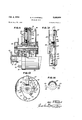
Figs. 1, 2 and 3 are elevational views showin the exterior appearance of the spinning reels;
Fig. 4 is a sectional view of one form of reel taken along line 4-4 of Fig. 1;
Fig. 5 is a plan view of the reel shown in Fig. 4, partly in section, and having its cover removed to show the line hook in retracted position;
Fig. 6 is an elevational view of the reel of Fig. 5 with the spool removed and a portion of the drum webbing broken away;
Fig. 7 is a view similar to Fig. 5 which shows the line hook in line pick-up position;
Figs. 8 and 9 are perspective views of the parts forming the means for securing the line hook to the line hook shaft;
Fig. 10 is a plan view of the means secured to the inner end of the line hook shaft of the spinning reel of Fig. 4 for rotating the shaft;
Fig. 11 is an elevation, partly in section, and with part of the casing and cover broken away, of a modified form of spinning reel;
Fig. 12 is an elevation of a part of the reel of Fig. 11, showing more clearly the driving means for the drum,
Fig. 13 is a sectional view taken along line l3-I3 of Fig. 12; and,
Fig. 14 is an elevational View of the bevel gear supported on and driven by the drive shaft.
By reference first to Figs. 1 through 4, my spinning reel (one for left-hand operation) will be seen to comprise a casing 26 provided with a peripheral flange 2!. A reel supporting bracket 22 having a rod-engaging spring portion 23 is secured to the casing 29 by having an arm 24 soldered, welded or by any other means attached to the casing.
A cover 25 is secured to the casing 26 by having its rear edge 26 received within flange 2i of the casing. A spring member 2'! (Fig. 2) which may be a part of bracket 22 or may merely be secured thereto, extends forwardly below the cover member 25 and has at its outer end a bend 28 adapted to engage the front edge of the cover. An opening 29 is formed centrally in the front of the cover and contains a collar 35 of reasonably hard material through which fishing line is adapted to pass.
The casing 2!) has a plurality of studs 3! secured to its rear face by which a gear housing 32 may be secured to it by screws 33. A hollow spindle 35, provided at one end with a flange 35, is supported by the casing 25 and by the gear housing 32, its flange 35 being welded or soldered to the outer face of the gear housing 32. This form of support serves also to strengthen the gear housing by bracing its central portion. The spindle 34 extends forwardly of the casing 20 and a substantial part of its forward end is threaded.
A hollow drive shaft 35 is supported on the rear portion of the hollow spindle 34 and is provided with a spur gear 37 secured to it as by welding. A crank shaft 38 having a flange 38 extends through an opening 49 in the casing at, the flange 39 abutting the rim of the opening 4e.
The crank shaft 38 is further supported by a bushing 4| which in turn is mounted in a flanged opening 42 in gear housing 32. A crank 23 is mounted on the outer end of crank shaft 38 by a screw 44 extending through it and threaded into the crank shaft. A driving gear 45 is mounted on the crank shaft 38, between the easing 20 and the gear housing 32, it being welded or soldered thereto and engaging the spur gear 31 secured to the drive shaft 35. Thus, by rotation of the crank 43 the drive shaft 36 is rotated on the spindle 34.
A line hook supporting drum 46 having a supporting web 41 and a hub 43 is mounted on the outer end of the drive shaft 36 and is adapted to be driven thereby by reason of a key 49 which is welded or otherwise secured to the inside of hub 48 and enters a keyway or slot 53 formed in the outer end of the drive shaft. The drum is maintained in position on the drive shaft by a nut 5! threaded onto the outer end of the spindle 34.
A spool comprising a hub 52, a front wall 53, and a back or rear wall 54, is adapted to be mounted on the outer end of the spindle beyond the drum retaining nut 5| and is supported thereon for free rotation upon a bushing 55. A washer 5B is interposed between the rear face of the back wall 54 of the spool and the drum retaining nut 5|.
The peripheral edge of the front wall 53 of the spool is provided with an inwardly extending projection 51 for a purpose that will be subsequently described. The rear wall 54 of the spool is formed with a rearwardly extending peripheral flange 58 which extends beneath the forward edge 59 of the peripheral wall of the drum 46. This latter construction serves to prevent fishing line being wound on the spool from getting behind the back wall of the spool and thereby becoming entangled.
The spool itself is maintained on the outer end of the hollow spindle by my novel drag attachment. This attachment comprises a drag rod 60 extending completely through the spindle and having a plate cl secured to its forward end, its rear end being threaded and being adapted to extend beyond the flanged end 35 of the spindle. A key 62 is secured as by welding to the drag rod 80, and to the plate 6! if desirable, and is adapted when the drag attachment is in operative position to enter a keyway or slot 63 in the outer end of the spindle whereby the drag attachment is maintained non-rotatable. A drag adjusting nut 84 is threaded onto the rear end of the drag rod 60, which is adjacent the crank 43 of the reel, and abuts against the flanged end 35 of the spindle. A friction disc or pad 35 is interposed between the plate El of the drag attachment and the front wall 53 of the spool. When the adjusting nut 63 is screwed onto the drag rod 68 and abuts the flanged end 35 of the spindle the plate 5| is drawn toward the spool and forces the friction disc 55 against its front wall 53, is drawn toward the spool and thereby imposing a drag or resistance to rotation upon the spool. It will be apparent that the degree of drag imposed upon the spool may be readily varied by this means from zero to a very substantial amount and that this adjustment may be easily performed on the same side of the reel at which the reel operating crank 43 is located.
Referring now to Figs. 4 through 10 the apparatus by which line may be wound upon the spool will be described. A line hook it i supported outside the peripheral wall 46 of the drum on a bracket 11 having slots 12 formed therein either of which is adapted to fit over the fiatted outer end 1.3 of a line hook shaft 34, which is supported in a bushing .15 welded or otherwise. secured to the webbing 41 of the drum. The bracket 11 is provided with a loop 16 which receives one end of the line hook 10. This end of the line hook is provided with a notch, the bracket being provided with a corresponding slot 11. A lock washer 18 having an opening '19 therein to receive the upper end of the line hook shaft i4 is adapted to fit over the bracket II and is provided with a projection 86 which its into the slot 11 and into the notch of the line hook m to hold the line hook in the bracket. The assembly of the line hook Hi; the bracket H and the lock washer I8 is secured to the outer end of the line hook shaft 14 by a screw and when so secured the line hook is prevented from moving relatively to the line hook shaft 74.
A. plate 8|, seen most clearly in Fig. 10 is provided with a slotted opening 82, adapted to receive the inner end of the line hook shaft 14, and with a pin 83, is adapted to be secured to the inner end of the line hook shaft 14 by a screw 84. Rotation of the plate 8| about the axis of the line hook shaft 14 causes theline hook shaft and the supported line hook to be rotated. By this means the line hook may be moved to line pick-up position as illustrated in Figs. 4 and '7, or to its retracted position at which line may be freely withdrawn from the spool, as best illustrated in Figs. 5 and 6. It will be noted that when in line pick-u-p position the distal end or tip of the line hook 'lll extends outwardly below the inwardly extending peripheral projection 5'! of the front wall 53 of the spool. By reason of this it is assured that line will be picked up by the line hook when it is rotated in its line pick-up position.
A substantially circular plate 84' (Figs. 4 and 6) provided with a pair of pins 85 and 8B is freely supported on a spacer bushing 81 which in turn is mounted on the drive shaft 35. A friction disc or pad 88 is also mounted on the drive shaft and is located between the plate '85 and the front face of casing 20. A coil spring so is maintained in compression, encircling the drive shaft, between the webbing 47 of the drum and the circular plate 84 and serves to maintain the plate 84 in contact with the friction disc 88 whereby free rotation of the plate 84 about the drive shaft, 36 is prevented. This apparatus cooperates with the plate iii and the pin 83, supported by the line hook shaft M, to move the line hook into and out of line pick-up position.
Its operation is as follows: When the drum is rotated by the drive shaft in one direction the pin 86 will engage the pin 83 and rotate the line hook shaft M. to move the line'hook to its retracted position as shown in Fig. 5 and when the drum is rotated in the opposite direction the pin 85 will engage the pin 83 to rotate the line hook shaft 14 to move the line hook to line pick up position as shown in Figs. 4 and 7. For the purposes of initiating the rotation of plate iii and line hook shaft l4, pins 85 and 8'5, as may be seen in Fig. 6, extend at about an angle of so degrees from the plane of the circular plate 8 3. Furthermore, in order to limit the rotation of the line hook shaft If and to prevent the pin 83 from moving far enough to the right'as seen in Fig. 4 so that it will not be engaged by either the pin 85 or 85, the plate 81 is so shaped (see 6 10 that its shoulders engage the webbing 41 of the drum to prevent but limited rotation.
As was initially stated, the reel of Figs. 1 through 10 is a left-hand'reel, that is it is shaped to be operated for reeling in line by rotation :of the crank 43 in a counterclockwise direction as seen in Fig. l, and is adapted to be operated to permit casting, that is, to be operated to retract line hook 10 from its line pickup position, by rotation of the crank 43 in a clockwise -direction as seen in Fig. 1. However, the reel as illustrated may be very simply modified to operate as a right-hand reel by the following minor changes.
First of all, a different line hook should be mounted in bracket II, that is, one designed for right-hand operation of the reel. Such a line hook however may be generally similar to that shown but willobviously have to be differently bent so that its distal end will extend beneath the peripheral projection 5? of the spool 53. Secondly, the bracket 7| must be removed from the line hook shaft 74 and replaced thereon by means of the second slot 12 so that its position would be 90 degrees clockwise of the showing in Fig. 7. In this position a right-hand line hook will be in a retracted position. The third minor change which is not absolutely necessary for temporary use of the reel as a right-handed reel but which is desirable if the reel shown is to be manufactured for relatively permanent use as a right-handed reel, is to form the threads on-the outer end of the spindle 34 as right-hand threads rather than as left-hand. threads which are desirable for use in the left-handed reel.
It may be stated here, if his not already apparent, that little more than one-half a revolution of the crank shaft 43 need be made to move the line hook from one of its positions to the other and that no manual operation other than that of turning the crank 43 need be employed to accomplish this end.
Referring now to Figs. 11 through 14, a modifled reel (again one for left-hand operation) which in all major respects is similar to that illustrated and described in connection with Figs. 1 through 10 will be described. The major difference between this reel and that shown in Figs. 1 through 10 is the apparatus for rotating the line hook about the spool and for moving it to line pick-up position and to its retracted position. Before this is described, however a few minor differences might be noted.
The first of these minor differences is in the construction of the spool. It will be noted in this respect thatthe rearwardly extending flange 58 formed at the periphery of the back wall 54 of the spool is at right angles thereto while in the previous reel it was at about 60 degrees thereto. Also, the inwardly extending projection 51 formed on the periphery ofthe front wall 53 of the spool is slightly different. Both of these differenceshcwever, are merely matters of choice as either spool may be used equally well in either reel. The spool of the reel of Figs. 11 through 14 is perhaps preferable as it may be somewhat easier and less expensive to manufacture.
Another minor difference in the reels is in the design of the drag adjusting nut 64. This difference, however, is readily apparent by a comparison of Figs. 4 and 11, and it is again merely a matter of choice of design and need not further be described. a
' In the modified form of spinning reel shown in Figs. 11 through 14 the line hook 10 is supported on the line hook shaft 14 in the same manner as it is in the previously described reel. Furthermore, the line hook shaft 14 is similarly mounted in a bushing 15 which is secured to the webbing I of a slightly difierent form of drum having a peripheral wall IOI. This drum is provided with a hub I02 which is secured to a bearing or bushing I03 freely mounted on a drive shaft I04. A segmental bevel gear I (having teeth only throughout about 180 degrees of its circumference) is secured to the inner end of the line hook shaft 14 by a screw I06. By means of this gear I05 the line hook shaft may be rotated to move the line hook to line pick-up position or to its retracted position. A second similar bevel gear I01 which engages bevel gear I05 is mounted on drive shaft I04 and is secured thereto against rotation by reason of a flat I00 formed on the drive shaft. This bevel gear I01 is maintained in position by a friction plate I 09 urged against it by a nut I I 0 which is threaded on the threaded end of the spindle 34 and to which the friction plate I 09 is secured as by welding.
Upon rotation of the drive shaft I04 bevel gear I01 is rotated thereby in turn rotating the bevel gear I05 and the line hook shaft 14. Depending upon the direction of rotation of the drive shaft the line hook will be moved to either line pickup position or to its retracted position.
In order, however, that the gear I05 will be rotated by the gear I01 when the latter is rotated, it is necessary that the drum be held against rotation itself until at least a small degree of relative rotation between it and gear I01 is achieved. This is accomplished by means of a pair of friction devices supported on a pair of lugs II I secured to the webbing I00 of the drum. These friction devices comprise wire rods H2 which support at their outer ends friction pads H3 which are adapted to rest against the friction plate I08. Thus when the bevel gear I01 is rotated and attempts to rotate the gear I05 any tendency on the part of the drum to rotate itself, thereby avoiding the necessity for the rotation of gear I05, is overcome because the friction devices just described provide suflicient resistance to the rotation of the drum to cause bevel gear I05 to rotate first.
A second pair of lugs H4 and I I5 is also provided in addition to the lugs I I I for a purpose to be now described.
By reference to Fig. 14 it will be noted that the bevel gear I01 is provided with wing sections I I6 and II? on which are formed, respectively, lugs H8 and H9. When the bevel gear I01 has been rotated sufficiently in one direction so that its lugs H8 and III! engage the lugs III, the line hook 10 will have been moved to its line pick-up position and further rotation of gear I01 will cause or effect rotation of the drum to wind line upon the spool. Rotation of the bevel gear I01 in the opposite direction will cause retraction of the line hook 10 until the lugs I I8 and I I9 engage the pair of lugs H4 and H5 at which point continued rotation of the bevel gear I 01 in this direction will serve no useful purpose. However, the pair of lugs I I4 and H5 is provided primarily to make it possible to modify this reel so that it will operate as a right-hand reel, these lugs then performing the function of lugs III. Such modification of the reel now being described to change it to a right-hand operating one is exactly the same as was required to make the same change in the reel of Figs. 1 through 10 and therefore need not be described.
A stabilizer spring member I20 supported by the lug H5 and extending to the peripheral wall IOI of the drum may be provided to exert a very slight force against the lug I IQ of the gear I01 to prevent unnecessary play between that lug and the lug III when the gear I01 is driven to wind line upon the spool. It will serve the same function in a right-hand reel without modification except it will then cooperate with the lug H5.
It will be apparent from the above description of two forms of spinning reels constructed in accordance with my invention that various modifications might be made without departing from the scope of my invention and it should, therefore, be understood that my invention should not be limited except to the extent set forth in the appended claims.
I claim:
1. In a spinning reel the combination of a casing, a spindle supported by the casing, a hollow drive shaft mounted on and concentric with the spindle, means mounted on the casing for rotating the drive shaft on the spindle, a spool for fishing line mounted on said spindle adjacent one end of the drive shaft, said spool having a front wall and a rear wall, the front wall having an inwardly extending projection around its periphery and the back wall having a rearwardly extending peripheral flange, a drum supported by and concentric with the drive shaft and adapted to be rotated thereby, a line hook supported substantially at the peripheral surface of said drum, means supported by said drum inwardly from the peripheral surface thereof for moving the line hook into line pick-up position and for retracting it therefrom, and means independent of said drum and supported by said drive shaft which cooperates with the line hook moving means when the drum is rotated in one direction to move the line hook into line pick-up position and when the drum is rotated in the op" posite direction to retract it therefrom, the distal end of said line hook when in line pick-up position extending beneath the inwardly extending projection on the periphery of the front wall of the spool, and the peripheral surface of the drum extending over the rearwardly extending flange of the back wall of the spool.
2. In a spinning reel the combination of a casing, a spindle supported by the casing and extending a substantial distance forward of its point of support by the casing, said spindle having an axial bore extending therethrough, a hollow drive shaft mounted on and concentric with the spindle and located toward the rear end of the spindle, a spool for fishing line mounted for free rotation on the forward end of the spindle, a rotatable drum supported on the drive shaft and having a line hook which is adapted to wind line on the spool when the drum is rotated, a driving gear secured to the drive shaft at its rear end, means supported by the casing and extending rearwardly therefrom for rotating said drive shaft, said means including a gear which engages the driving gear on the drive shaft, a drag rod extending through the bore in the spindle and through the casing and adapted to extend slightly beyond either end of the spindle and rearwardly of the casing, the rear end of said rod being threaded, an adjusting nut threaded on the threaded end of the rod and abutting the adjacent end of the spindle, and a plate secured to the opposite or forward end of the drag rod and overlying a portion of the front Wall of the spool, said plate being adapted to frictionally engage the front wall of said spool, when the adjusting nut on the rear end of the drag rod is threaded onto said rod, whereby rotation of the spool on the spindle may be restrained to varying degrees depending upon the amount that the adjustment nut is screwed onto the drag rod.
3. In a spinning reel the combination as set forth in claim 2 which includes a friction disc interposed between the friction plate and the front wall of the spool and adapted to be compressed therebetween.
4. In a spinning reel the combination as set forth in claim 2 which includes a slot formed in the forward end of the spindle and a key secured to the outer end of the drag rod and adapted to be received in the spindle slot whereby the drag rod is nonrotatable relative to the spindle.
5. In a spinning reel the combination of a cas ing, a spindle supported by the casing, a hollow drive shaft mounted on and concentric with the spindle, means mounted on the casing for rotat ing the drive shaft on the spindle, said spindle also being adapted to support a spool for fishing line, a drum supported by and concentric with the drive shaft and adapted to be rotated thereby, a line hook, a line hook shaft supported by the drum substantially at right angles to the axis of the drum and extending through the peripheral wall of the drum, means for securing the line hook to the outer end of said line hook shaft, means secured to the inner end of the line hoot: shaft for rotating said line hook shaft to move the line hook into line pick-up position and to retract it therefrom, means independent of the drum and supported by the drive shaft which is engageable with the means for rotating the line hook shaft so that when the drive shaft is rotated. and there is relative movement between the means on the inner end of the line hook shaft and the means independent of said drum in one direction the line hook is moved into line pickup position and when there is relative motion in the opposite direction the line hook is retracted from line pick-up position, and friction means for assuring such relative movement during initial rotation of the drive shaft in each direction until the line hook is in one of its limiting positions.
6. In a spinning reel the combination set forth in claim 5 in which the drum is secured directly to the drive shaft for rotation thereby, in which the means secured to the inner end of the line hook shaft comprises a plate extending generally in a plane at right angles to the axis of the line hook shaft and having a pin supported by it substantially radially of the drum, and in which the means independent of the drum comprises a circular plate supported by the drive shaft at right angles to the axis thereof and having a pair of pins mounted on it and extending outwardly from it, one of said pair of pins being adapted to engage the pin supported by the line hook shaft when the drum is rotated in one direction whereby the line hook is moved to line pick-up position, and the other of said pair of pins being adapted to engage the pin of the line hook shaft when the drum is rotated in the opposite direction whereby the line hook is retracted from line pick-up position.
7. In a spinning reel the combination as set forth in claim 6, in which said friction means includes a friction disc interposed between the drive shaft supported circular plate and the cas ing and a spring surrounding the drive shaft and urging the circular plate against the friction disc, whereby the circular plate is held stationary relative to the drive shaft until one of the pins supported by it is engaged by the pin of the line hook shaft with sufficient force to overcome the frictional resistance.
8. In a spinning reel the combination as set forth in claim 6 in which the lug supporting plate secured to the inner end of the line hook shaft limits rotation of the line hook shaft to approximately degrees by engaging a portion of the drum.
9. In a spinning reel the combination as set forth in claim 5 in which the drum is freely supported on the drive shaft, in which the means supported on the inner end of the line hook shaft comprises a degree bevel gear, and in which the means independent of said drum comprises a bevel gear secured to the drive shaft for rotation thereby and engageable with the bevel gear supported by the line hook shaft whereby when the drive shaft is rotated in one direction the line hook shaft is rotated to move the line hook into line pick-up position and when the drive shaft is rotated in the opposite direction the line hook shaft is rotated to retract the line hook from line pick-up position.
10. In a spinning reel the combination as set forth in claim 9 which includes a pair of lugs formed on the bevel gear secured to the drive shaft, and a pair of lugs affixed to the drum, said pairs of lugs being adapted to engage each other when the drive shaft supported bevel gear is rotated, whereby the drum is rotated thereby.
11. In a spinning reel the combination as set forth in claim 10 in which said friction means includes a substantially circular friction plate nonrotatably secured to the spindle adjacent the bevel gear supporting end of the drive shaft and means supported by the drum and frictionally engaging said friction plate, whereby the drum is held stationary until said pairs of lugs engage each other.
OPIE H. CAMPBELL.
References Cited in the file of this patent UNITED STATES PATENTS Number Name Date 1,140,868 Bennett May 25, 1915 1,187,840 Illingworth June 20, 1916 1,687,579 McMullan Oct. 16, 1928 2,282,156 Benes May 5, 1 42 2,363,533 King Nov. 28, 1944 2,498,987 Duncan Feb. 28, 1950 2,507,457 Rix May 9, 1950 2,521,543 Shakespeare et a1. Sept. 5, 1 50 FOREIGN PATENTS Number Country Date 804,230 France July 27, 1936 195,577 Switzerland Mar. 2, 1938 598,412 Great Britain Feb. 18, 1948
Priority Applications (1)
| Application Number | Priority Date | Filing Date | Title |
|---|---|---|---|
| US176644A US2668024A (en) | 1950-07-29 | 1950-07-29 | Spinning reel |
Applications Claiming Priority (1)
| Application Number | Priority Date | Filing Date | Title |
|---|---|---|---|
| US176644A US2668024A (en) | 1950-07-29 | 1950-07-29 | Spinning reel |
Publications (1)
| Publication Number | Publication Date |
|---|---|
| US2668024A true US2668024A (en) | 1954-02-02 |
Family
ID=22645229
Family Applications (1)
| Application Number | Title | Priority Date | Filing Date |
|---|---|---|---|
| US176644A Expired - Lifetime US2668024A (en) | 1950-07-29 | 1950-07-29 | Spinning reel |
Country Status (1)
| Country | Link |
|---|---|
| US (1) | US2668024A (en) |
Cited By (6)
| Publication number | Priority date | Publication date | Assignee | Title |
|---|---|---|---|---|
| US2775377A (en) * | 1954-10-04 | 1956-12-25 | Burlington Industries Inc | Machines for producing bows and pompons from ribbons |
| US2783952A (en) * | 1954-06-04 | 1957-03-05 | Great Lakes Products Inc | Spinning reel |
| US2797055A (en) * | 1953-12-28 | 1957-06-25 | Lee A Mcdonald | Casting reel |
| US2904281A (en) * | 1954-01-25 | 1959-09-15 | Aldrich L Jackson | Spinning type fishing reel |
| US3226051A (en) * | 1964-03-04 | 1965-12-28 | Pflueger Corp | Line guide control for a spinning reel |
| US3241787A (en) * | 1962-09-11 | 1966-03-22 | Lauterbach Richard Ernest | Line pickup guide means for a spinning reel |
Citations (11)
| Publication number | Priority date | Publication date | Assignee | Title |
|---|---|---|---|---|
| US1140868A (en) * | 1912-10-19 | 1915-05-25 | Clover Leaf Mfg Company | Bobbin. |
| US1187840A (en) * | 1914-07-06 | 1916-06-20 | Alfred Holden Illingworth | Bait-casting reel used in angling. |
| US1687579A (en) * | 1924-10-22 | 1928-10-16 | Western Electric Co | Material holder |
| FR804230A (en) * | 1936-02-27 | 1936-10-19 | Hardy Brothers Alnwick Ltd | Improvements to Fixed Drum Type Fishing Reels |
| CH195577A (en) * | 1937-03-08 | 1938-02-15 | Wenzel Thoener | Folding device for the line guide for fishing reels with a fixed drum. |
| US2282156A (en) * | 1941-02-14 | 1942-05-05 | Edwin J Benes | Fishing reel spool |
| US2363533A (en) * | 1941-09-20 | 1944-11-28 | Frank A King | Reeling mechanism |
| GB598412A (en) * | 1945-09-03 | 1948-02-18 | Charles Bowell | Improvements in or relating to fishing-reels |
| US2498987A (en) * | 1946-08-19 | 1950-02-28 | Everett S Duncan | Fishing reel |
| US2507457A (en) * | 1947-11-03 | 1950-05-09 | Robert W Rix | Fishing reel |
| US2521543A (en) * | 1949-02-14 | 1950-09-05 | Shakespeare Co | Fishing reel of the type known as spinning reel |
-
1950
- 1950-07-29 US US176644A patent/US2668024A/en not_active Expired - Lifetime
Patent Citations (11)
| Publication number | Priority date | Publication date | Assignee | Title |
|---|---|---|---|---|
| US1140868A (en) * | 1912-10-19 | 1915-05-25 | Clover Leaf Mfg Company | Bobbin. |
| US1187840A (en) * | 1914-07-06 | 1916-06-20 | Alfred Holden Illingworth | Bait-casting reel used in angling. |
| US1687579A (en) * | 1924-10-22 | 1928-10-16 | Western Electric Co | Material holder |
| FR804230A (en) * | 1936-02-27 | 1936-10-19 | Hardy Brothers Alnwick Ltd | Improvements to Fixed Drum Type Fishing Reels |
| CH195577A (en) * | 1937-03-08 | 1938-02-15 | Wenzel Thoener | Folding device for the line guide for fishing reels with a fixed drum. |
| US2282156A (en) * | 1941-02-14 | 1942-05-05 | Edwin J Benes | Fishing reel spool |
| US2363533A (en) * | 1941-09-20 | 1944-11-28 | Frank A King | Reeling mechanism |
| GB598412A (en) * | 1945-09-03 | 1948-02-18 | Charles Bowell | Improvements in or relating to fishing-reels |
| US2498987A (en) * | 1946-08-19 | 1950-02-28 | Everett S Duncan | Fishing reel |
| US2507457A (en) * | 1947-11-03 | 1950-05-09 | Robert W Rix | Fishing reel |
| US2521543A (en) * | 1949-02-14 | 1950-09-05 | Shakespeare Co | Fishing reel of the type known as spinning reel |
Cited By (6)
| Publication number | Priority date | Publication date | Assignee | Title |
|---|---|---|---|---|
| US2797055A (en) * | 1953-12-28 | 1957-06-25 | Lee A Mcdonald | Casting reel |
| US2904281A (en) * | 1954-01-25 | 1959-09-15 | Aldrich L Jackson | Spinning type fishing reel |
| US2783952A (en) * | 1954-06-04 | 1957-03-05 | Great Lakes Products Inc | Spinning reel |
| US2775377A (en) * | 1954-10-04 | 1956-12-25 | Burlington Industries Inc | Machines for producing bows and pompons from ribbons |
| US3241787A (en) * | 1962-09-11 | 1966-03-22 | Lauterbach Richard Ernest | Line pickup guide means for a spinning reel |
| US3226051A (en) * | 1964-03-04 | 1965-12-28 | Pflueger Corp | Line guide control for a spinning reel |
Similar Documents
| Publication | Publication Date | Title |
|---|---|---|
| US2668025A (en) | Fishing reel | |
| US2391840A (en) | Spring-wound cord-controlled take-up reel | |
| US2600558A (en) | Fishing reel with nonrotary bobbin | |
| US2229470A (en) | Bait-casting reel | |
| US2546465A (en) | Spinning type fishing reel | |
| US2034917A (en) | Conical reel side plate | |
| US2668024A (en) | Spinning reel | |
| US1187840A (en) | Bait-casting reel used in angling. | |
| GB1444455A (en) | Thread storage feeder herbicidal composition | |
| US3586255A (en) | Spinning reel with winding drum brake | |
| US3074664A (en) | Closed face spinning reel | |
| US2633307A (en) | Casting reel | |
| US2314616A (en) | Fishing reel | |
| US2290662A (en) | Fishing reel | |
| US3034741A (en) | Spinning reel | |
| US3223347A (en) | Spin-casting fishing reel | |
| US2136438A (en) | Adjustable tension clutch for fishing reels | |
| US2879954A (en) | Fishing reel | |
| US2327469A (en) | Fishing rod and reel | |
| US2723808A (en) | Auto-spinner reel | |
| GB711140A (en) | Improvements in or relating to means for rotatably supporting reels or bobbins of wire or the like | |
| US2584020A (en) | Fishing rod and reel | |
| US2599189A (en) | Line pickup device for fishing reel having nonrotary drums | |
| US3006573A (en) | Spinning reel | |
| US2901193A (en) | Spinning type fishing reel |