US266749A - Dumping-car - Google Patents
Dumping-car Download PDFInfo
- Publication number
- US266749A US266749A US266749DA US266749A US 266749 A US266749 A US 266749A US 266749D A US266749D A US 266749DA US 266749 A US266749 A US 266749A
- Authority
- US
- United States
- Prior art keywords
- dumping
- car
- platform
- wheel
- axle
- Prior art date
- Legal status (The legal status is an assumption and is not a legal conclusion. Google has not performed a legal analysis and makes no representation as to the accuracy of the status listed.)
- Expired - Lifetime
Links
Images

Classifications
-
- B—PERFORMING OPERATIONS; TRANSPORTING
- B61—RAILWAYS
- B61D—BODY DETAILS OR KINDS OF RAILWAY VEHICLES
- B61D9/00—Tipping wagons
- B61D9/02—Tipping wagons characterised by operating means for tipping
-
- Y—GENERAL TAGGING OF NEW TECHNOLOGICAL DEVELOPMENTS; GENERAL TAGGING OF CROSS-SECTIONAL TECHNOLOGIES SPANNING OVER SEVERAL SECTIONS OF THE IPC; TECHNICAL SUBJECTS COVERED BY FORMER USPC CROSS-REFERENCE ART COLLECTIONS [XRACs] AND DIGESTS
- Y10—TECHNICAL SUBJECTS COVERED BY FORMER USPC
- Y10T—TECHNICAL SUBJECTS COVERED BY FORMER US CLASSIFICATION
- Y10T74/00—Machine element or mechanism
- Y10T74/15—Intermittent grip type mechanical movement
- Y10T74/1526—Oscillation or reciprocation to intermittent unidirectional motion
- Y10T74/1532—Rack actuator
Definitions
- My invention relates to improvements in dumping-cars; and it consists in the peculiar construction and arrangement of parts, as hereinafter fully described.
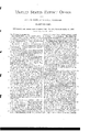
- Figure l is a plan of my improved dumping-car inverted.
- Fig. 2 is a longitudinal sectional elevation taken on the line a: no of Fig. 1.
- Fig. 3 is an end elevation with parts ofthe frame sectioned on the line 1 g of Fig. 2.
- Fig. 4 is a detail of the dumping-gear.
- the platform is made in two parts, A, divided lengthwise along the middle, which parts are hinged near about their middlelongitudinally to the car-frame at B, so as to betilted on said hinges for dumping to the sides of the car, respectively, as shown in Fig. 3.
- the inner edges of the divided platform have sides 0 to prevent the load from falling between them when raised up and thejoint where they meet together opened; and between said sides and the outer edges over which the earth is dumped they have a rod or bar, D, extending from end to end, so that the earth will be piled up around it when loaded on, and said rod will thereby act as a' retarder to the earth when discharging and prevent it from sliding off rapidly and projecting so far away from the track as it otherwise does, thus enabling the earth to be dropped upon the top of the embankment where it is required for building and repairs, instead of projecting over and beyond the top.
- the two parts A A are respectively connected by bars E with the cross-heads F of vertically-reciprocatingslides G, tittedin suitable guideways, H, of the truck-frame, each slide having a toothed rack, I, gearing with a pinion, J, which gears with another pinion, K, on the axle, and titted loosely thereon with a clutch for connectingand disconnecting it, as required.
- the clutch consists of the spring-key L, fitted in a groove, M, of the axle, so as to spring out into a groove.
- N in the pinion when released, and thereby connects the pinion with the axle for being turned by said axle, and a slidingcollar, O, on the axle, for depressing or releasing the spring by being shifted forward and backward on it by the bar P, which has one end coiled or otherwise fitted around the axle and connected by a hook or flange, Q, with said collar, for working it, the other end being arranged in connection with the pin R of a tappct-wheel, S, and also provided with a spring, T, whereby the clutch may be connected and disconnected at will by turning the wheel, for which said wheel is provided with arms U, to be reached under the sides of the car, but is by preference provided with.
- a grooved pulley, WV to be worked from the end of the car by a chain, X, hand-wheel Z, and pulley Y in a similar manner as the brakes are worked.
- the platform is connected by gear, as above described, near each end, with axles thereat, and there aretwo clutch-levers extending therefrom to the tappet-whcel.
- the clutches when disconnected, are kept so by setting the tappet-wheel in the proper position by the handwheel Z, which is secured in position bya ratchet and pawl at (1..
- the handwheel is turned so as to swing arms U in the direction indicated by the arrow until arrested by dog a, hanging down from the platform, to allow the lovers to escape from the pins of the tappet-wheel.
- the springs T then quickly engage the clutches for dumping the platform.
- the locomotive will then be backed up or started ahead a little, according as the car is hitched to it, which will cause the cross-heads F to rise and dump the platform. Then a corresponding reverse motion will return the platforms to their places.
- the dog a which is wedge-shaped, will pass down on the other side of arm U and move the tappet-wheel sufticiently to disconnect the clutches at the moment that the slides G return to the starting-point.
- the dog a is jointed at b to the platform and draws over the edge 0 of the frame when the platform rises, so as to be projected to the other side of arm U when the platform goes back.
- the tappet-wheel may then be set, as before, by the hand-wheel Z and ratchet a to holdthe clutches out of gear.
- the cross heads F are connected to the lower ends of the slides Gr, so as to lift more directly under the platforms, by the connecting-rods E, and also so that the slides G are guided better and easier than they would be if connected at the top.
Landscapes
- Engineering & Computer Science (AREA)
- Transportation (AREA)
- Mechanical Engineering (AREA)
- Emergency Lowering Means (AREA)
Description
J. E. B'EMISW DUMPING GAR. Q
M Patented Oct. 31, 1882.
I i i i I I i INVBNTOR ATTORNEYS.
Urvrrnn 'rarns ATENT Brien.
JOHN E. BEMIS, OF WAUPUN, WISCONSIN.
DUMPlNG-CAR.
SPECIFICATION forming part of Letters Patent No. 266,749, dated October 31, 1882,
Application filed May 8, 18852. (ModeL) T 0 all whom it may concern Be it known that I, JOHN E. BEMIs, of Waupun, in the county of Fond du Lac and State of vVisconsin,have invented a new and lmproved Dumping-Gar, of which the following is a full, clear, and exact description.
My invention relates to improvements in dumping-cars; and it consists in the peculiar construction and arrangement of parts, as hereinafter fully described.
Reference is to be had to the accompanying drawings, forming part of this specification, in which similar letters of reference indicate corresponding parts in all the figures.
Figure l is a plan of my improved dumping-car inverted. Fig. 2 is a longitudinal sectional elevation taken on the line a: no of Fig. 1. Fig. 3 is an end elevation with parts ofthe frame sectioned on the line 1 g of Fig. 2. Fig. 4 is a detail of the dumping-gear.
The platform is made in two parts, A, divided lengthwise along the middle, which parts are hinged near about their middlelongitudinally to the car-frame at B, so as to betilted on said hinges for dumping to the sides of the car, respectively, as shown in Fig. 3. The inner edges of the divided platform have sides 0 to prevent the load from falling between them when raised up and thejoint where they meet together opened; and between said sides and the outer edges over which the earth is dumped they have a rod or bar, D, extending from end to end, so that the earth will be piled up around it when loaded on, and said rod will thereby act as a' retarder to the earth when discharging and prevent it from sliding off rapidly and projecting so far away from the track as it otherwise does, thus enabling the earth to be dropped upon the top of the embankment where it is required for building and repairs, instead of projecting over and beyond the top.
To gear the dumping -platform with the axles of the car for utilizing the power of the locomotive to work the platform, the two parts A A are respectively connected by bars E with the cross-heads F of vertically-reciprocatingslides G, tittedin suitable guideways, H, of the truck-frame, each slide having a toothed rack, I, gearing with a pinion, J, which gears with another pinion, K, on the axle, and titted loosely thereon with a clutch for connectingand disconnecting it, as required. The clutch consists of the spring-key L, fitted in a groove, M, of the axle, so as to spring out into a groove. N, in the pinion when released, and thereby connects the pinion with the axle for being turned by said axle, and a slidingcollar, O, on the axle, for depressing or releasing the spring by being shifted forward and backward on it by the bar P, which has one end coiled or otherwise fitted around the axle and connected by a hook or flange, Q, with said collar, for working it, the other end being arranged in connection with the pin R of a tappct-wheel, S, and also provided with a spring, T, whereby the clutch may be connected and disconnected at will by turning the wheel, for which said wheel is provided with arms U, to be reached under the sides of the car, but is by preference provided with. a grooved pulley, WV, to be worked from the end of the car by a chain, X, hand-wheel Z, and pulley Y in a similar manner as the brakes are worked.
The platform is connected by gear, as above described, near each end, with axles thereat, and there aretwo clutch-levers extending therefrom to the tappet-whcel. The clutches, when disconnected, are kept so by setting the tappet-wheel in the proper position by the handwheel Z, which is secured in position bya ratchet and pawl at (1.. Then, when itis desired to connect the gears for dumping the load, the handwheel is turned so as to swing arms U in the direction indicated by the arrow until arrested by dog a, hanging down from the platform, to allow the lovers to escape from the pins of the tappet-wheel. The springs T then quickly engage the clutches for dumping the platform. The locomotive will then be backed up or started ahead a little, according as the car is hitched to it, which will cause the cross-heads F to rise and dump the platform. Then a corresponding reverse motion will return the platforms to their places. As the platform settles back, the dog a, which is wedge-shaped, will pass down on the other side of arm U and move the tappet-wheel sufticiently to disconnect the clutches at the moment that the slides G return to the starting-point. The dog a is jointed at b to the platform and draws over the edge 0 of the frame when the platform rises, so as to be projected to the other side of arm U when the platform goes back. The tappet-wheel may then be set, as before, by the hand-wheel Z and ratchet a to holdthe clutches out of gear.
The cross heads F are connected to the lower ends of the slides Gr, so as to lift more directly under the platforms, by the connecting-rods E, and also so that the slides G are guided better and easier than they would be if connected at the top.
Having thus fully described my invention, I claim as new and desire to secure by Letters Patent- 1. The combination of retarding rods or bars D with the dumping-platform of a car, substantially as described,
wheel for working the clutch-levers, geared with a hand-wheel, Z, located on the end of the car, by pulleys W and Y and chains X,
substantially as described.
JOHN EMMONS BEMIS.
Witnesses:
MICHAEL J. SULLIVAN, ELI HOOKER.
Publications (1)
| Publication Number | Publication Date |
|---|---|
| US266749A true US266749A (en) | 1882-10-31 |
Family
ID=2336000
Family Applications (1)
| Application Number | Title | Priority Date | Filing Date |
|---|---|---|---|
| US266749D Expired - Lifetime US266749A (en) | Dumping-car |
Country Status (1)
| Country | Link |
|---|---|
| US (1) | US266749A (en) |
Cited By (1)
| Publication number | Priority date | Publication date | Assignee | Title |
|---|---|---|---|---|
| US20070266750A1 (en) * | 2006-05-15 | 2007-11-22 | Shannon Hollis | Silicone surfactant-based agricultural formulations and methods for the use thereof |
-
0
- US US266749D patent/US266749A/en not_active Expired - Lifetime
Cited By (1)
| Publication number | Priority date | Publication date | Assignee | Title |
|---|---|---|---|---|
| US20070266750A1 (en) * | 2006-05-15 | 2007-11-22 | Shannon Hollis | Silicone surfactant-based agricultural formulations and methods for the use thereof |
Similar Documents
| Publication | Publication Date | Title |
|---|---|---|
| US266749A (en) | Dumping-car | |
| US777020A (en) | Dumping-car. | |
| US613279A (en) | Freight-cap | |
| US1305351A (en) | stamslaw gandek | |
| US952943A (en) | Wagon. | |
| US415484A (en) | Dumping-car | |
| US695344A (en) | Ore-car. | |
| US315892A (en) | Dumping-car | |
| US244954A (en) | Dumping-car | |
| US527117A (en) | Timothy long | |
| US804870A (en) | Ore-distributing car. | |
| US1268830A (en) | Dumping-car. | |
| US288103A (en) | Dumping-platform | |
| US1265063A (en) | Dumping-car. | |
| US275096A (en) | Railway-track layer | |
| US867726A (en) | Dumping-car. | |
| US416393A (en) | And august zincke | |
| US1443890A (en) | Elevating mechanism for dumping trucks | |
| US251931A (en) | Dumping-car | |
| US580974A (en) | Unloading attachment for railway flat-cars | |
| US515678A (en) | Ditching-machine | |
| US318170A (en) | Dumping-car | |
| US662669A (en) | Log-loading device. | |
| US710820A (en) | Dirt-loading apparatus. | |
| US370500A (en) | Car-brake |