US2633003A - Multitemperature refrigerator - Google Patents
Multitemperature refrigerator Download PDFInfo
- Publication number
- US2633003A US2633003A US187415A US18741550A US2633003A US 2633003 A US2633003 A US 2633003A US 187415 A US187415 A US 187415A US 18741550 A US18741550 A US 18741550A US 2633003 A US2633003 A US 2633003A
- Authority
- US
- United States
- Prior art keywords
- compartment
- refrigerant
- evaporator
- temperature
- liner
- Prior art date
- Legal status (The legal status is an assumption and is not a legal conclusion. Google has not performed a legal analysis and makes no representation as to the accuracy of the status listed.)
- Expired - Lifetime
Links
Images


Classifications
-
- F—MECHANICAL ENGINEERING; LIGHTING; HEATING; WEAPONS; BLASTING
- F25—REFRIGERATION OR COOLING; COMBINED HEATING AND REFRIGERATION SYSTEMS; HEAT PUMP SYSTEMS; MANUFACTURE OR STORAGE OF ICE; LIQUEFACTION SOLIDIFICATION OF GASES
- F25D—REFRIGERATORS; COLD ROOMS; ICE-BOXES; COOLING OR FREEZING APPARATUS NOT OTHERWISE PROVIDED FOR
- F25D23/00—General constructional features
- F25D23/06—Walls
- F25D23/069—Cooling space dividing partitions
-
- F—MECHANICAL ENGINEERING; LIGHTING; HEATING; WEAPONS; BLASTING
- F25—REFRIGERATION OR COOLING; COMBINED HEATING AND REFRIGERATION SYSTEMS; HEAT PUMP SYSTEMS; MANUFACTURE OR STORAGE OF ICE; LIQUEFACTION SOLIDIFICATION OF GASES
- F25D—REFRIGERATORS; COLD ROOMS; ICE-BOXES; COOLING OR FREEZING APPARATUS NOT OTHERWISE PROVIDED FOR
- F25D11/00—Self-contained movable devices, e.g. domestic refrigerators
- F25D11/02—Self-contained movable devices, e.g. domestic refrigerators with cooling compartments at different temperatures
- F25D11/022—Self-contained movable devices, e.g. domestic refrigerators with cooling compartments at different temperatures with two or more evaporators
-
- F—MECHANICAL ENGINEERING; LIGHTING; HEATING; WEAPONS; BLASTING
- F25—REFRIGERATION OR COOLING; COMBINED HEATING AND REFRIGERATION SYSTEMS; HEAT PUMP SYSTEMS; MANUFACTURE OR STORAGE OF ICE; LIQUEFACTION SOLIDIFICATION OF GASES
- F25B—REFRIGERATION MACHINES, PLANTS OR SYSTEMS; COMBINED HEATING AND REFRIGERATION SYSTEMS; HEAT PUMP SYSTEMS
- F25B5/00—Compression machines, plants or systems, with several evaporator circuits, e.g. for varying refrigerating capacity
- F25B5/04—Compression machines, plants or systems, with several evaporator circuits, e.g. for varying refrigerating capacity arranged in series
-
- F—MECHANICAL ENGINEERING; LIGHTING; HEATING; WEAPONS; BLASTING
- F25—REFRIGERATION OR COOLING; COMBINED HEATING AND REFRIGERATION SYSTEMS; HEAT PUMP SYSTEMS; MANUFACTURE OR STORAGE OF ICE; LIQUEFACTION SOLIDIFICATION OF GASES
- F25C—PRODUCING, WORKING OR HANDLING ICE
- F25C2400/00—Auxiliary features or devices for producing, working or handling ice
- F25C2400/10—Refrigerator units
-
- F—MECHANICAL ENGINEERING; LIGHTING; HEATING; WEAPONS; BLASTING
- F25—REFRIGERATION OR COOLING; COMBINED HEATING AND REFRIGERATION SYSTEMS; HEAT PUMP SYSTEMS; MANUFACTURE OR STORAGE OF ICE; LIQUEFACTION SOLIDIFICATION OF GASES
- F25D—REFRIGERATORS; COLD ROOMS; ICE-BOXES; COOLING OR FREEZING APPARATUS NOT OTHERWISE PROVIDED FOR
- F25D17/00—Arrangements for circulating cooling fluids; Arrangements for circulating gas, e.g. air, within refrigerated spaces
- F25D17/04—Arrangements for circulating cooling fluids; Arrangements for circulating gas, e.g. air, within refrigerated spaces for circulating air, e.g. by convection
-
- F—MECHANICAL ENGINEERING; LIGHTING; HEATING; WEAPONS; BLASTING
- F25—REFRIGERATION OR COOLING; COMBINED HEATING AND REFRIGERATION SYSTEMS; HEAT PUMP SYSTEMS; MANUFACTURE OR STORAGE OF ICE; LIQUEFACTION SOLIDIFICATION OF GASES
- F25D—REFRIGERATORS; COLD ROOMS; ICE-BOXES; COOLING OR FREEZING APPARATUS NOT OTHERWISE PROVIDED FOR
- F25D25/00—Charging, supporting, and discharging the articles to be cooled
- F25D25/02—Charging, supporting, and discharging the articles to be cooled by shelves
- F25D25/022—Baskets
-
- F—MECHANICAL ENGINEERING; LIGHTING; HEATING; WEAPONS; BLASTING
- F25—REFRIGERATION OR COOLING; COMBINED HEATING AND REFRIGERATION SYSTEMS; HEAT PUMP SYSTEMS; MANUFACTURE OR STORAGE OF ICE; LIQUEFACTION SOLIDIFICATION OF GASES
- F25D—REFRIGERATORS; COLD ROOMS; ICE-BOXES; COOLING OR FREEZING APPARATUS NOT OTHERWISE PROVIDED FOR
- F25D25/00—Charging, supporting, and discharging the articles to be cooled
- F25D25/02—Charging, supporting, and discharging the articles to be cooled by shelves
- F25D25/028—Cooled supporting means
-
- Y—GENERAL TAGGING OF NEW TECHNOLOGICAL DEVELOPMENTS; GENERAL TAGGING OF CROSS-SECTIONAL TECHNOLOGIES SPANNING OVER SEVERAL SECTIONS OF THE IPC; TECHNICAL SUBJECTS COVERED BY FORMER USPC CROSS-REFERENCE ART COLLECTIONS [XRACs] AND DIGESTS
- Y10—TECHNICAL SUBJECTS COVERED BY FORMER USPC
- Y10S—TECHNICAL SUBJECTS COVERED BY FORMER USPC CROSS-REFERENCE ART COLLECTIONS [XRACs] AND DIGESTS
- Y10S62/00—Refrigeration
- Y10S62/13—Insulation
Definitions
- MULTITEMPERATURE REFRIGERATQR Filed sept. 29. 195o ,5 sheets-sheet 4 March 31, 1953 w. D. JORDAN MULTITEMPERATURE REFRIGERATOR 5 Sheets-Shet 5 Filed sept. 29, 1950y Patented Mar. 3l, 1953 My -fmvtitri ist par 1 1 enter "ofi said-'refrigerated'spate; which lisais@ maybe*maintained'tavoid dehydration of Vege- "tallesj fruits and left-overa? thereby -aviding 'the n'eed'fforf'wrappingf oricovering "such food items.
- Another fpu'rpose is tof provide automatic 'deyfrosting'of the refrigerating evaporatorsurface in compartment 1 (mi whenever refrigerant yis not Vbeing supplied tofsaidtvevaporator.
- jrefrigeratorfiand l which isfinstalledfin .'orlreating 'system which "will supply" refrigerant to all the evaporators in series when refrigeration is needed in all of said four compartments, which will shut oif the supply of refrigerant to the evaporator in compartment (A) when that compartment comes down to the desired temperature, but will continue to supply refrigerant to the lower evaporator until compartments (C) and (D) come down to the desired temperature.
- Another purpose is to provide a hinged cover or door over one of said compartments, which Will open down 90 ⁇ to form a shelf on which to set articles when placing foods in or removing foods from the refrigerator.
- Another purpose is to provide a novel means of insulating the refrigerator, using two insulating materials of different conductivity characteristics, which enables me to use an insulation chamber of uniform thickness from topto bottom of the box, but to obtain greater insulating effect around the lower portion of the box where lthe temperature diiferential is greater.
- Fig. 1 is a front elevation with the door open
- Fig. 2 is a section on an enlarged scale on the line 2-2 of Fig. 1;
- Fig. 3 is a detailed vertical section of one side -of the structure illustrated in Fig.
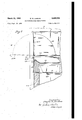
- Fig. 4 is a section on an enlarged scale on the jline 4-4 of Fig. 1, with the front door closed;
- Fig. 5 is a section on the line 5 5 of Fig. 2;
- Fig. 6 is a flow or cycling diagram
- Fig. 7 is a partial vertical section through a variant form.
- I generally indicatesany suitable supporting members vor feet upon which is mounted a base structure including any suitable front removable panel 2 and any suitablevfixedside walls 3 and rear wall 4.
- the bottoml 5 may be suitably apertured toper- ,mit the upward passageof air and the rear wall 4 may also be suitablyvvopened whereby air may .be circulated through the condensing unit space X defined within the above described structure.
- I may posirtion any suitable refrigerating unit, the details of which do not of themselves form --any part of the present invention.
- B diagrammatically indicates a combined compressor-motor unit of any suitable type
- I diagrammatically indicates tom wall I2, side walls I3, I4, and a hingedv door I5.
- Each such wall may have an outer ⁇ element a and an inner element b with any suitable lintervening insulating materials c.
- Youter members may, if desired, form upward conyspace above.
- the insulating effect of the bottom wall I2 and of the lower parts 'of the side and rear walls may be increased by inserts I6 or" more emcient insulation.
- the basic insulation c may be of berglas, or other suitable material, with the inserts I6 being of a material such as vSantocel, of low heat conductive characteristics.
- I can employ agrade ofY fiberglas ⁇ wardly extending flange 22a of the shelf 22.
- I provide an insulated housing of differential heat transfer or heat insulating characteristics, the lower part being more efficiently insulated than the upper.
- the cooling compartment will thus be understood to be bounded or defined by the inner elements b of the top, bottom, rear and side walls ⁇ the otherwise open front of the storage compartment being closed or closable by the hinged door I5 with any suitable sealing strips I1.
- I provide an insulating-separating shelf between the more highly insulated lower portion and the less highly insulated upper portion.
- I illustrate a horizontal insulated shelf structure I8 having side hangers or side walls I9 terminating in an outwardly extending flange 20 removably supported on any suitable abutments or supports 2
- the insulating partition I8 upwardly bounds a low temperature storage zone and downwardly bounds a high temperature storage zone.
- I illustrate a removable shelf positioned to form the floor of the higher temperature compartment, with a pan or tray directly below the shelf, said pan or tray providing static air insulation to separate the two compartments. It may also be used for storing fresh meats and other foods at a temperature somewhere between the temperatures maintained above and below said pan or tray.
- ⁇ I provide an evaporator structure in the form of a horizontally extending shelf or partition 22 and depending side walls 23. Secured to the lower surface of the top wall 22 and secured to the outer surfaces of the side walls 23 are evaporator coils or units 24a, 24h, and 24e, which may, for example, be connected in series.
- the shelf 22 is separated from the walls 23 by intervening rubber elements 25.
- a sealing strip 26 extends around the sides and rear edges of the upper out- It will be understood that rubber or a suitable rubber substitute may be employed to the end that the space below the anges 22a. is sealed from the
- the lower edges of the walls 23a are supported by bushings 21 through which screws 28 extend into threaded members 29. It will be understood that the above described structure can readily be removed outwardly through the open door when the screws 28 are removed.
- the ice trays 30 are shown as positioned just below the insulating partitioning means
- I employ a single door, exposing a full area of a single liner front of the refrigerator. This involves a single set of hardware on the door and a single seal around the periphery of the door. However, I employ separate closures 34, 3
- any, in the high humidity section will travel by vapor pressure differential to the upper evaporators where it deposits as frost when the evaporator coils 50a and Ela are receiving refrigerant.
- the frost melts quickly and flows down through the drain ducts or tubes to the trough 55.
- I prevent moisture accumulation in the insulation by causing any vapor that may enter it to pass through the louvres 80 to the lower temperature evaporator surfaces, where it condenses out as frost on the ice shelf.
- the insulation is always kept dry and will be kept dry even with poor sealing of the outer enclosure.
- My entire above described refrigerating system may be readily removed by loosening the breaker strips 90 at the front of the refrigerator.
- the liner comprising the inner wall elements b, remains in the shell or housing.
- the back wall of the enclosure as will be clear, for example, from Fig. 2, is without openings.
- the entire evaporator structure may be forwardly and outwardly removed as a unit. This includes the ducts 63 and 63a, as it is a simple matter to slot the insulation and to slot the upper wall portion b to permit unitary removal of the entire evaporator system.
- the capillary 60 conducts liquid refrigerant from the above described condensing unit to the upper coils 50a. and Sla, when the temperature of the chamber to which the bulb 62 is subjected holds the thermal modulating valve 6
- closes, causing the refrigerant to flow through the check valve 'lo to the duct 63, and thus to the low temperature evaporator coils.
- refrigerant is not supplied to the upper coils 50a and Ela, they warm up quickly to surrounding air temperature, and the frost accumulation, if any, melts and flows olf to the pan 55.
- water is placed in the ice trays 30, a rapid transfer of heat to the ice shelf tubing 24h occurs and the cubes are frozen at a somewhat higher suction pressure, resulting in higher capacity of the condensing unit.
- the lower temperature compartments are held at around 0 F., isv cold enough to storeY food at the desired temperature, but is not so cold as to cause the control to stop the compressor. Thus ice is frozen without cycling.
- the relative humidity in compartment b between the shelves i0 and i8 is controlled by opening or closing the shutter unit 4
- the ports In dry weather, the ports may be restricted, and in highly humid weather they may be Widely opened. As a general practice, they need be changed only as between summer and winter ⁇ conditions.
- any moisture that enters the insulation due to poor sealing of the enclosure or shell, will automatically pass through the louvered openings and be deposited on the ice shelf, because of the vapor pressure differential between the ice shelf surface and that of the warmer liner surface exposed to the insulation. It will be noted that the zero zone evaporators are spaced within and out of contact with the walls or iioor of the liner proper.
- the side evaporator plates 23 and their coils 24a and 24e may be at -l0 F., during the operation of the condensing unit, but due to spacing them inwardly from the liner wall b, the heat gain from the outside to the liner wall and the heat loss from the liner wall to the plates balances out with the liner temperature from 10 to 15 F., above that of the evaporator. The necessary vapor pressure differential is thus maintained during the on cycle.
- ⁇ I also prevent ice formation on the liner walls at and above the longitudinal partition by retarding heat ow from the liner wall above, to the colder liner wall at and below the ice shelf 22, by making the louvres 80 elongated and staggered in two or three rows to make a tortuous heat path. With this construction, no ice forms on the walls of the liner above the louvres.
- a domestic refrigerator adapted for storing both frozen and unfrozen foods and for freezing foods, ice cubes and the like, a single liner and an enclosing shell, a layer of insulation between said liner and shell, said shell and liner being open on one side, a single insulated door pivoted to the structure so formed and adapted to be moved into and out of closing position in relation to said open side, a horizontal insulating partitioning means positioned within the liner and adapted to form a separation between an upper storage compartment for unfrozen food and a lower storage compartment for ice cubes and frozen food, said partitioning means being readily removable from the liner, an ice freezing shelf mounted within the liner, extending to and sealed to the side and rear walls of the liner and having a forward edge adjacent the inner surfaceA of the door when the door is closed, said ice vfreezing shelf having an'evaporating coil on dening with the, ioorfro ,.inefsnoif and with aqiceii?
- a liner In a two-temperature refrigerator, a liner, an insulated enclosure surrounding said liner, an insulating partitioning means separating the interior of said liner into itwo food storage compartments, refrigerating means for maintaining an above freezing temperature in a warmer compartment, refrigerating means for maintaining a below freezing temperature in a colder compartment, each o-f said refrigerating means including a refrigerant evaporator, a condensing unit serving both of said refrigerating means, refrigerant conduit means connecting said evaporators in series with said condensing unit, including a duct extending from said condensing unit to the evaporator in the warmer compartment, refrigerant con-trol means adapted to prevent the delivery of volatile refrigerant from the condensing unit to the refrigerating means in the warmer compartment when a predetermined temperature is reached in said warmer compartment, and ⁇ ley-pass means for maintaining a continued supply of volatile refrigerant to the refrigerating means in the
- an insulated enclosure means within said enclosure for dening refrigerated storage, space, partition means separating ⁇ said storage, space linto a warmer compartment and a'colder compartment, a refrigerantevaporator for ea'chfof said com# partments, saidevaporatorsllbeingarranged in series, ⁇ agrefrigerant condensing unit locatedoutr Sido: the.
- refrigerated Space including a Comoros- Sorcnnol afzoondonsor, a supply duct extending from said unit to the evaporator in the warmer compartment, pressure reduction means in the line of delivery 4of refrigerant to said evaporator, a duct :connecting the evaporator in the warmer compartment to the evaporator in the colder compartment, a return'duct extending from the evaporator in the colder compartment to the suction side of the compressor of the refrigerant condensing unit, such duct constituting the sole return to the compressor, a normally open valve in the supply duct extending from the condense ing unit to the evaporator in the warmer compartment, located on the delivery side -of the pressure reduction means, means for closing it in response to a predetermined temperature condition in the warmer compartment, and a bypass passage between the pressure reducing means and said valve through which refrigerant may pass to the evaporator in the colder compartment without passing through the evaporator in
- the structure of claim 4 characterized by and including a single shell within the insulated enclosure and surrounding all -of the refrigerated storage space.
- the structure 4of claim 4 characterized by and including a single shell within the insulated enclosure and surrounding all ⁇ of the refrigerated storage space, means for defining an ice freezing space in the colder compartment, the shell being apertured in communication with sai-d space, whereby the insulation in the insulated enclosure is in vapor transfer relationship with the ice freezing space.
- the struc-ture of claim 4 characterized by and including a single shell within the insulated enclosure and surrounding all of the refrigerated storage space, means for defining an ice freezing space in the colder compartment, the shell being apertured in communication with said space, whereby the insulation in the insulated enclosure is in vapor transfer relationship with the ice freezing space, with the apertures in the shell being closely spaced and extending substantially across the walls of the liner, whereby the vertic-al heat transfer by conduction in said apertured wall is substantially reduced.
- the structure of claim 4 characterized by and including a single shell within the insulated enclosure and surrounding all of the refrigerated storage space, the partition means being constituted by an insulating partition located within the shell, and sealing means between partition and shell adapted substantially to reduce temperature conduction therebetween.
- the structure of claim 4 characterized by and including a single shell within the insulated enclosure and surrounding all of the refrigerated storage space, the evaporator in the colder compartment being spaced inwardly from said shell, whereby the shell is maintained at a temperature substantially higher than the temperature within the colder compartment.
Description
W. D. JORDAN MULTITEMPERATURE REFRIGERATOR March 31, 1953 5 Sheets-Sheet 1 Filed Sept. 29, 1950 d A 7 M March 3l, 1953 w. D. JoRDAN MULTITEMPERATURE REFRIGERATOR s `sheets-:inset 2 Filed Sept. 29, 1950 /lll l/l/ f r f f 5 Sheets-Sheet 3 I?? vena? Mez/yn e jordan y PGM@ M zorweys W D JORDAN MULTITEMPERATURE REFRIGERATOR Fig 5 3 7 4l c 2 e. Mus 4 March 31, 1953 Flled Sept 29, 1950 March 3l, 1953` w. n. JQRDAN 2,633,003
MULTITEMPERATURE REFRIGERATQR Filed sept. 29. 195o ,5 sheets-sheet 4 March 31, 1953 w. D. JORDAN MULTITEMPERATURE REFRIGERATOR 5 Sheets-Shet 5 Filed sept. 29, 1950y Patented Mar. 3l, 1953 My -fmvtitri ist par 1 1 enter "ofi said-'refrigerated'spate; which lisais@ maybe*maintained'tavoid dehydration of Vege- "tallesj fruits and left-overa? thereby -aviding 'the n'eed'fforf'wrappingf oricovering "such food items.
"(C) ice` cubesfreezngfeompartment across the central area oflisaid`refrigerated"space, be-
Jl'ow ellow leveLTnia'kng iti convenient `to` insert ire'lled trayswithout lmost other' refrigeratorsp iiiing Watenffwhereas 'lacefthe 'ic'e trays' 'iat l (D) ALfrozenfood'storagefcompartfnetacrdss the lower portion of "said" refrigerated space," with :the frozen foodipackageslstored inbins or Aleaskets `which pull "outyand tilt .forf convenient access '-to any` packages Wanted.
Another fpu'rpose is tof provide automatic 'deyfrosting'of the refrigerating evaporatorsurface in compartment 1 (mi whenever refrigerant yis not Vbeing supplied tofsaidtvevaporator.
-Another purpose is-"to-maintain-the relative ,humiciifty in --compartment- (A), substantially higher than in` most other refrigerators, which is-accomplished -bv-usingfan evaporator of light WeightV andflovv 'total heat-.content and adapted 10 Warm .up .quicklyj e119; fheptiemperawrefof. the surrounding-air whenvtheg refrigerant supplyv is shut off, w hich a'vo id s5 acumulating' moisture, as -frostx out oi the Vvsurrounding airv andffood except during `the relatively brief'lperiods when thel condensing unit isrunning. When the conlation `of frost mltrsfguicisly land. part ofthe moisture is re ev'apefated by the @Bending-air rpose t 35 nwansiin-L compartment (B),
ttnductionfbffheatf rourrdin 'said' rerigeratedfsp'ace', Esaid?break? bef rigerators use two liners ft of hardwarefandlt" results in a liigli ltretrefputpselis tain theffprfap one fcorfderising* unit a n d one electric control or switch.
-``Another` purpose relative i humidityffi `the Walls' 0f l"the `liner Sur- 10 "ted-fat he ever ofthe-separation* be- `n' th e lowA emp alture-compartments-land Atheijtigrier -temperat fer empartmentsg thereby {enabl'irigme'to man in "compartments Cl'iand (DY-adjacent '5to "said -itiierfwails;bittrtofmantaifthe'ntie walls-above Satdarkat temperature higher han` iding ny licei formatibnfnfsa-idfliner 'feateflaeirtsgettion fthe -saiingf the buter 4shell ort'enclosure.
jrefrigeratorfiand lwhich isfinstalledfin .'orlreating 'system which "will supply" refrigerant to all the evaporators in series when refrigeration is needed in all of said four compartments, which will shut oif the supply of refrigerant to the evaporator in compartment (A) when that compartment comes down to the desired temperature, but will continue to supply refrigerant to the lower evaporator until compartments (C) and (D) come down to the desired temperature.
Another purpose is to provide a hinged cover or door over one of said compartments, which Will open down 90 `to form a shelf on which to set articles when placing foods in or removing foods from the refrigerator.
Another purpose is to provide a novel means of insulating the refrigerator, using two insulating materials of different conductivity characteristics, which enables me to use an insulation chamber of uniform thickness from topto bottom of the box, but to obtain greater insulating effect around the lower portion of the box where lthe temperature diiferential is greater.
Other purposes willappear in the specifications and claims.V
I illustrate my invention more or less diagram- ,matically in the accompanying drawings, where- Fig. 1 is a front elevation with the door open; Fig. 2 is a section on an enlarged scale on the line 2-2 of Fig. 1;
Fig. 3 is a detailed vertical section of one side -of the structure illustrated in Fig.
Fig. 4 is a section on an enlarged scale on the jline 4-4 of Fig. 1, with the front door closed;
Fig. 5 is a section on the line 5 5 of Fig. 2;
Fig. 6 is a flow or cycling diagram; and
Fig. 7 is a partial vertical section through a variant form.
Like parts are indicated by like symbols vthroughout the specication and drawings.
Referring, for example, to Figs. 4 and 5, I generally indicatesany suitable supporting members vor feet upon which is mounted a base structure including any suitable front removable panel 2 and any suitablevfixedside walls 3 and rear wall 4. The bottoml 5 may be suitably apertured toper- ,mit the upward passageof air and the rear wall 4 may also be suitablyvvopened whereby air may .be circulated through the condensing unit space X defined within the above described structure. Within the condensing unit space X I may posirtion any suitable refrigerating unit, the details of which do not of themselves form --any part of the present invention. B diagrammatically indicates a combined compressor-motor unit of any suitable type, and I diagrammatically indicates tom wall I2, side walls I3, I4, and a hingedv door I5. Each such wall may have an outer` element a and an inner element b with any suitable lintervening insulating materials c. The
Youter members may, if desired, form upward conyspace above.
tinuations of the previously described walls 3 and l IIl. The insulating effect of the bottom wall I2 and of the lower parts 'of the side and rear walls may be increased by inserts I6 or" more emcient insulation. I do not wish to be limited to any specific means, but, `as an example, the basic insulation c may be of berglas, or other suitable material, with the inserts I6 being of a material such as vSantocel, of low heat conductive characteristics. Or I can employ agrade ofY fiberglas `wardly extending flange 22a of the shelf 22.
4 having a heat transfer coefficient well below the grade used in the upper zone. Thus, as will be clear from Figs. 4 and 5, I provide an insulated housing of differential heat transfer or heat insulating characteristics, the lower part being more efficiently insulated than the upper.
The cooling compartment will thus be understood to be bounded or defined by the inner elements b of the top, bottom, rear and side walls` the otherwise open front of the storage compartment being closed or closable by the hinged door I5 with any suitable sealing strips I1.
In the device, when nally assembled, I provide an insulating-separating shelf between the more highly insulated lower portion and the less highly insulated upper portion. For example, I illustrate a horizontal insulated shelf structure I8 having side hangers or side walls I9 terminating in an outwardly extending flange 20 removably supported on any suitable abutments or supports 2|. Thus the insulating partition I8 upwardly bounds a low temperature storage zone and downwardly bounds a high temperature storage zone. As an alternate insulating means between the two compartments, I illustrate a removable shelf positioned to form the floor of the higher temperature compartment, with a pan or tray directly below the shelf, said pan or tray providing static air insulation to separate the two compartments. It may also be used for storing fresh meats and other foods at a temperature somewhere between the temperatures maintained above and below said pan or tray.
Considering rst the low temperature storage zone,` I provide an evaporator structure in the form of a horizontally extending shelf or partition 22 and depending side walls 23. Secured to the lower surface of the top wall 22 and secured to the outer surfaces of the side walls 23 are evaporator coils or units 24a, 24h, and 24e, which may, for example, be connected in series. The shelf 22 is separated from the walls 23 by intervening rubber elements 25. A sealing strip 26 extends around the sides and rear edges of the upper out- It will be understood that rubber or a suitable rubber substitute may be employed to the end that the space below the anges 22a. is sealed from the The lower edges of the walls 23a are supported by bushings 21 through which screws 28 extend into threaded members 29. It will be understood that the above described structure can readily be removed outwardly through the open door when the screws 28 are removed.
The cycling connection for the evaporators 24a, 24h, 24C, will later be described. It will be understood, however, that the space below the insulating partitioning means Iilis kept at a temperature substantially below freezing. Thus ice trays 30 may be positioned on the shelf 22 in the space between that shelf and the partitioning means I8. The front opening ofthis ice cube freezing space may be closed, for example, by a door 3l horizontally transversely pivoted at its lower edge as at -32 and provided with a suitable operating handle 1 5 Any Suitable removable storage Abaskets 31 may be ture approximating 40 F. in the space above the partition I8.
The ice trays 30 are shown as positioned just below the insulating partitioning means |8 at a level from which they can be conveniently inserted and removed with a minimum of lifting and thus a minimum of spillage. They are 1ocated below elbow height, resulting in easier access.
I employ a single door, exposing a full area of a single liner front of the refrigerator. This involves a single set of hardware on the door and a single seal around the periphery of the door. However, I employ separate closures 34, 3| and 45 for the cold storage compartment, the ice tray compartment and the moist storage compartment, respectively.
I avoid any accumulation of condensed moisture in the high humidity storage zone by removing excess moisture, if any, for evaporation in the outside trough 55. The excess water vapor, if
any, in the high humidity section will travel by vapor pressure differential to the upper evaporators where it deposits as frost when the evaporator coils 50a and Ela are receiving refrigerant. When refrigerant is not passing, the frost melts quickly and flows down through the drain ducts or tubes to the trough 55.
I prevent moisture accumulation in the insulation by causing any vapor that may enter it to pass through the louvres 80 to the lower temperature evaporator surfaces, where it condenses out as frost on the ice shelf. Thus the insulation is always kept dry and will be kept dry even with poor sealing of the outer enclosure.
My entire above described refrigerating system may be readily removed by loosening the breaker strips 90 at the front of the refrigerator. The liner, comprising the inner wall elements b, remains in the shell or housing. The back wall of the enclosure, as will be clear, for example, from Fig. 2, is without openings. But the entire evaporator structure may be forwardly and outwardly removed as a unit. This includes the ducts 63 and 63a, as it is a simple matter to slot the insulation and to slot the upper wall portion b to permit unitary removal of the entire evaporator system.
In considering the cycling operation, the capillary 60 conducts liquid refrigerant from the above described condensing unit to the upper coils 50a. and Sla, when the temperature of the chamber to which the bulb 62 is subjected holds the thermal modulating valve 6| in the open position. However, even though the modulating valve 6| may be closed, the by-pass valve 10 is still effective to permit the passage of the volatile refrigerant to and through the coils 24a, 24h and 24e.
When the upper or high temperature storage compartment is cooled'to the desired temperature of from 36 to 40 F., the thermal valve 6| closes, causing the refrigerant to flow through the check valve 'lo to the duct 63, and thus to the low temperature evaporator coils. When refrigerant is not supplied to the upper coils 50a and Ela, they warm up quickly to surrounding air temperature, and the frost accumulation, if any, melts and flows olf to the pan 55. When water is placed in the ice trays 30, a rapid transfer of heat to the ice shelf tubing 24h occurs and the cubes are frozen at a somewhat higher suction pressure, resulting in higher capacity of the condensing unit. During this ice-freezing operation, the lower temperature compartments are held at around 0 F., isv cold enough to storeY food at the desired temperature, but is not so cold as to cause the control to stop the compressor. Thus ice is frozen without cycling.
In highly humid weather, frequent door openings will introduce moisture into the high temperature compartment, but when the door is closed, any excess vapor will deposit as frost on the coils 50a and 5|a, which melts and runs down the drain ducts 54 whenever refrigerant is not supplied to the upper evaporators. Thus, continually automatic defrosting is provided. A much higher relative humidity is maintained in this compartment than in most other refrigerators, since the evaporators accumulate frost only while refrigerant is being circulated through said evaporators; when the refrigerant supply is shut off or the compressor is not running, the frost melts quickly and a portion of the moisture is re-evaporated by the surrounding air. The relative humidity in compartment b between the shelves i0 and i8 is controlled by opening or closing the shutter unit 4|. In dry weather, the ports may be restricted, and in highly humid weather they may be Widely opened. As a general practice, they need be changed only as between summer and winter` conditions.
As above mentioned, any moisture that enters the insulation due to poor sealing of the enclosure or shell, will automatically pass through the louvered openings and be deposited on the ice shelf, because of the vapor pressure differential between the ice shelf surface and that of the warmer liner surface exposed to the insulation. It will be noted that the zero zone evaporators are spaced within and out of contact with the walls or iioor of the liner proper. The side evaporator plates 23 and their coils 24a and 24e may be at -l0 F., during the operation of the condensing unit, but due to spacing them inwardly from the liner wall b, the heat gain from the outside to the liner wall and the heat loss from the liner wall to the plates balances out with the liner temperature from 10 to 15 F., above that of the evaporator. The necessary vapor pressure differential is thus maintained during the on cycle.
` I also prevent ice formation on the liner walls at and above the longitudinal partition by retarding heat ow from the liner wall above, to the colder liner wall at and below the ice shelf 22, by making the louvres 80 elongated and staggered in two or three rows to make a tortuous heat path. With this construction, no ice forms on the walls of the liner above the louvres.
I claim:
l. In a domestic refrigerator adapted for storing both frozen and unfrozen foods and for freezing foods, ice cubes and the like, a single liner and an enclosing shell, a layer of insulation between said liner and shell, said shell and liner being open on one side, a single insulated door pivoted to the structure so formed and adapted to be moved into and out of closing position in relation to said open side, a horizontal insulating partitioning means positioned within the liner and adapted to form a separation between an upper storage compartment for unfrozen food and a lower storage compartment for ice cubes and frozen food, said partitioning means being readily removable from the liner, an ice freezing shelf mounted within the liner, extending to and sealed to the side and rear walls of the liner and having a forward edge adjacent the inner surfaceA of the door when the door is closed, said ice vfreezing shelf having an'evaporating coil on dening with the, ioorfro ,.inefsnoif and with aqiceii? W'll BQIQHS. Of: 19119111161? a 1035/5355501" oso-.SDaoo-ior frozenioodsftiiowniis of .Said liner having :multiplo ,openingsinaaiigninontwith tho Spano ,between thehorizontai, pantitionine.v moans ondthorioafroozing shoitwhoroby inoisiinoirnay nass from.; thospaoeoutsiolo of; the linen-tain@ Senso insidofof tno. liner or ieetyno evaporator positioned-:in thenmoor. food-Storage Compartmont .formed within the linornnd aboveatho Said horizontal 1oartitionine. orleansA refrigerant .oondonsingiunit. positioned ,outs` f.. the iinonnnd itssnrrounding insulation., Said' oondonsine .unit including a compressor and condenser, a capillary tube extending from the condenser, and conduit connections between said capillary tube and said evaporators and between said evaporators and said condensing unit, a thermal-controlled switch for said condensing unit, said switch having an element responsive to the temperature of the frozen food storage space, and a thermally actuated valve assembly between the cap-illary tube and the plate-type evaporator in the high temperature storage compartment, said valve assembly including a heat sensitive member responsive to the temperature of the zone of unfrozen storage, whereby the ow of refrigerant from the condenser to the plate-type evaporator is stopped and the refrigerant is by-passed to the low temperature evaporator at a predetermined food storage temperature, and is started at a somewhat higher temperature.
2. In a two-temperature refrigerator, a liner, an insulated enclosure surrounding said liner, an insulating partitioning means separating the interior of said liner into itwo food storage compartments, refrigerating means for maintaining an above freezing temperature in a warmer compartment, refrigerating means for maintaining a below freezing temperature in a colder compartment, each o-f said refrigerating means including a refrigerant evaporator, a condensing unit serving both of said refrigerating means, refrigerant conduit means connecting said evaporators in series with said condensing unit, including a duct extending from said condensing unit to the evaporator in the warmer compartment, refrigerant con-trol means adapted to prevent the delivery of volatile refrigerant from the condensing unit to the refrigerating means in the warmer compartment when a predetermined temperature is reached in said warmer compartment, and `ley-pass means for maintaining a continued supply of volatile refrigerant to the refrigerating means in the colder compartment when said refrigerant control means prevent the -delivery of refrigerant to the first refrigerating means.
3. In a two-temperature refrigerator, an insulated enclosure, an inside liner defining the refrigerated storage space, partitioning means separating said storage space into a warmer compartment and a colder compartment, a refrigerant evaporator in each of said compartments, a refrigerant condensing unit located Ioutside the refrigerated space, refrigerant conduit means connecting `said condensing unit to said evaporators in series, and extending from the refrigerant condensing unit to the evaporator in the warmer compartment, and refrigerant control means adapted to shut off the supply of refrig- 10 citant..ftofsaidfovanorotor ingoiawarmen coinnaitinont ,when -aforodotonnined@temperature is fotones-'infiniewannercompartmentwhile-por: mitting the .refrigerant ,tot continuel. o flew/to said evaporator in said colder`v compartmenu-there being alby-pass duct extending .from said refrigoront conduit. to the. evaporator in the "Colder compartment.
In atwo-temperature refrigerator, an insulated enclosure, means within said enclosure for dening refrigerated storage, space, partition means separating` said storage, space linto a warmer compartment and a'colder compartment, a refrigerantevaporator for ea'chfof said com# partments, saidevaporatorsllbeingarranged in series, `agrefrigerant condensing unit locatedoutr Sido: the. refrigerated Space including a Comoros- Sorcnnol afzoondonsor, a supply duct extending from said unit to the evaporator in the warmer compartment, pressure reduction means in the line of delivery 4of refrigerant to said evaporator, a duct :connecting the evaporator in the warmer compartment to the evaporator in the colder compartment, a return'duct extending from the evaporator in the colder compartment to the suction side of the compressor of the refrigerant condensing unit, such duct constituting the sole return to the compressor, a normally open valve in the supply duct extending from the condense ing unit to the evaporator in the warmer compartment, located on the delivery side -of the pressure reduction means, means for closing it in response to a predetermined temperature condition in the warmer compartment, and a bypass passage between the pressure reducing means and said valve through which refrigerant may pass to the evaporator in the colder compartment without passing through the evaporator in the warmer compartment.
5. The structure of claim 4 characterized by and including a -spring loaded valve in the bypass passage.
6. The structure of claim 4 characterized by and including a single shell within the insulated enclosure and surrounding all -of the refrigerated storage space.
7. The structure 4of claim 4 characterized by and including a single shell within the insulated enclosure and surrounding all `of the refrigerated storage space, means for defining an ice freezing space in the colder compartment, the shell being apertured in communication with sai-d space, whereby the insulation in the insulated enclosure is in vapor transfer relationship with the ice freezing space.
8. The struc-ture of claim 4 characterized by and including a single shell within the insulated enclosure and surrounding all of the refrigerated storage space, means for defining an ice freezing space in the colder compartment, the shell being apertured in communication with said space, whereby the insulation in the insulated enclosure is in vapor transfer relationship with the ice freezing space, with the apertures in the shell being closely spaced and extending substantially across the walls of the liner, whereby the vertic-al heat transfer by conduction in said apertured wall is substantially reduced.
9. The structure of claim 4 characterized by and including a single shell within the insulated enclosure and surrounding all of the refrigerated storage space, the partition means being constituted by an insulating partition located within the shell, and sealing means between partition and shell adapted substantially to reduce temperature conduction therebetween.
10. The structure of claim 4 characterized by and including a single shell within the insulated enclosure and surrounding all of the refrigerated storage space, the evaporator in the colder compartment being spaced inwardly from said shell, whereby the shell is maintained at a temperature substantially higher than the temperature within the colder compartment.
WAYNE D. JORDAN.
REFERENCES CITED The following references are of record in the file of this patent:
UNITED STATES PATENTS Number n 12 Name Date Kalischer Dec. 28, 1937 Briggman et al. Jan. 25, 1938 'Buchanan Oct. 25, 1938 Kalischer Oct. 25, 1938 Bronaugh et al. Dec. 27, 1938 Schweller Dec. 12, 1939 Kaufman Feb. 27, 1940 Iwashita Nov. 28, 1944 Tobey Oct. 16, 1945 Bauman Oct. 19, 1948 Groat Jan. l1, 1949 Richard Nov. 8, 1949 Kleist Jan. 31, 1950 Giiord July 18, 1950 Phillip July 18, 1950 Tobey Aug. 14, 1951
Priority Applications (1)
| Application Number | Priority Date | Filing Date | Title |
|---|---|---|---|
| US187415A US2633003A (en) | 1950-09-29 | 1950-09-29 | Multitemperature refrigerator |
Applications Claiming Priority (1)
| Application Number | Priority Date | Filing Date | Title |
|---|---|---|---|
| US187415A US2633003A (en) | 1950-09-29 | 1950-09-29 | Multitemperature refrigerator |
Publications (1)
| Publication Number | Publication Date |
|---|---|
| US2633003A true US2633003A (en) | 1953-03-31 |
Family
ID=22688883
Family Applications (1)
| Application Number | Title | Priority Date | Filing Date |
|---|---|---|---|
| US187415A Expired - Lifetime US2633003A (en) | 1950-09-29 | 1950-09-29 | Multitemperature refrigerator |
Country Status (1)
| Country | Link |
|---|---|
| US (1) | US2633003A (en) |
Cited By (16)
| Publication number | Priority date | Publication date | Assignee | Title |
|---|---|---|---|---|
| US2691872A (en) * | 1953-02-25 | 1954-10-19 | Philco Corp | Plural compartment refrigeration apparatus |
| US2693679A (en) * | 1953-03-24 | 1954-11-09 | Philco Corp | Plural compartment refrigeration apparatus |
| US2697916A (en) * | 1953-06-03 | 1954-12-28 | Seeger Refrigerator Co | Multiple temperature household refrigerator and method of refrigeration |
| US2741898A (en) * | 1951-07-09 | 1956-04-17 | Whirlpool Seeger Corp | Refrigerator evaporator |
| US2768510A (en) * | 1953-08-07 | 1956-10-30 | Westinghouse Electric Corp | Plural temperature refrigeration apparatus |
| US2791099A (en) * | 1953-02-27 | 1957-05-07 | Wayne D Jordan | Control system for multi-temperature refrigerators |
| US2874554A (en) * | 1954-03-22 | 1959-02-24 | Thore M Elfving | Refrigerating transport |
| DE1085899B (en) * | 1957-02-20 | 1960-07-28 | Siemens Elektrogeraete Gmbh | Refrigerator cooled with a chiller |
| US3142163A (en) * | 1962-02-06 | 1964-07-28 | Morphy Richards Astral Ltd | Refrigeration evaporators |
| US3216775A (en) * | 1964-07-06 | 1965-11-09 | Norman N Brenner | Beverage cabinets |
| FR2576676A1 (en) * | 1985-01-29 | 1986-08-01 | Selnor | REFRIGERATED CABINET WITH THREE COMPARTMENTS |
| US4627246A (en) * | 1984-07-02 | 1986-12-09 | General Electric | Refrigerator compartment partition and method of assembly |
| US5797280A (en) * | 1995-07-20 | 1998-08-25 | Daewoo Electronics Co., Ltd. | Refrigerator with an external air invasion prevention apparatus |
| US20080271475A1 (en) * | 2007-01-29 | 2008-11-06 | Wuesthoff Edward P | Refrigerator having compartment capable of converting between refrigeration and freezing temperatures |
| WO2009156328A2 (en) * | 2008-06-23 | 2009-12-30 | BSH Bosch und Siemens Hausgeräte GmbH | Refrigerator |
| WO2016206890A1 (en) * | 2015-06-22 | 2016-12-29 | BSH Hausgeräte GmbH | Refrigeration apparatus |
Citations (18)
| Publication number | Priority date | Publication date | Assignee | Title |
|---|---|---|---|---|
| US1002664A (en) * | 1909-09-21 | 1911-09-05 | William R Fitchet | Food-safe. |
| US1225054A (en) * | 1914-01-30 | 1917-05-08 | Milton C Powell | Kitchen-cabinet. |
| US2103683A (en) * | 1934-11-03 | 1937-12-28 | Westinghouse Electric & Mfg Co | Refrigeration apparatus |
| US2106591A (en) * | 1935-02-19 | 1938-01-25 | Gen Electric | Refrigerating system |
| US2133948A (en) * | 1935-04-06 | 1938-10-25 | Westinghouse Electric & Mfg Co | Refrigeration apparatus |
| US2133958A (en) * | 1937-01-21 | 1938-10-25 | Westinghouse Electric & Mfg Co | Humidity control for refrigerators |
| US2141459A (en) * | 1934-01-30 | 1938-12-27 | Refrigeration Patents Corp | Multiple compartment refrigerator |
| US2182824A (en) * | 1933-03-23 | 1939-12-12 | Gen Motors Corp | Refrigerating apparatus |
| US2191925A (en) * | 1935-04-30 | 1940-02-27 | Gen Motors Corp | Refrigerating apparatus |
| US2363530A (en) * | 1942-09-29 | 1944-11-28 | Stewart Warner Corp | Refrigerator |
| US2386919A (en) * | 1942-10-02 | 1945-10-16 | Westinghouse Electric Corp | Refrigeration apparatus |
| US2451903A (en) * | 1944-06-30 | 1948-10-19 | Philco Corp | Refrigerator having a heat dissipating device for the electric motor thereof |
| US2458589A (en) * | 1945-02-01 | 1949-01-11 | York Corp | Two temperature refrigeration unit |
| US2487182A (en) * | 1947-02-14 | 1949-11-08 | Seeger Refrigerator Co | Two-temperature refrigerator having means for defrosting |
| US2496220A (en) * | 1944-06-05 | 1950-01-31 | Dole Refrigerating Co | Domestic refrigerating unit |
| US2515212A (en) * | 1947-07-24 | 1950-07-18 | Nash Kelvinator Corp | Refrigerating apparatus |
| US2515892A (en) * | 1947-03-05 | 1950-07-18 | Nash Kelvinator Corp | Refrigerator insulation drying arrangement |
| US2563975A (en) * | 1948-09-24 | 1951-08-14 | Westinghouse Electric Corp | Two temperature refrigerator |
-
1950
- 1950-09-29 US US187415A patent/US2633003A/en not_active Expired - Lifetime
Patent Citations (18)
| Publication number | Priority date | Publication date | Assignee | Title |
|---|---|---|---|---|
| US1002664A (en) * | 1909-09-21 | 1911-09-05 | William R Fitchet | Food-safe. |
| US1225054A (en) * | 1914-01-30 | 1917-05-08 | Milton C Powell | Kitchen-cabinet. |
| US2182824A (en) * | 1933-03-23 | 1939-12-12 | Gen Motors Corp | Refrigerating apparatus |
| US2141459A (en) * | 1934-01-30 | 1938-12-27 | Refrigeration Patents Corp | Multiple compartment refrigerator |
| US2103683A (en) * | 1934-11-03 | 1937-12-28 | Westinghouse Electric & Mfg Co | Refrigeration apparatus |
| US2106591A (en) * | 1935-02-19 | 1938-01-25 | Gen Electric | Refrigerating system |
| US2133948A (en) * | 1935-04-06 | 1938-10-25 | Westinghouse Electric & Mfg Co | Refrigeration apparatus |
| US2191925A (en) * | 1935-04-30 | 1940-02-27 | Gen Motors Corp | Refrigerating apparatus |
| US2133958A (en) * | 1937-01-21 | 1938-10-25 | Westinghouse Electric & Mfg Co | Humidity control for refrigerators |
| US2363530A (en) * | 1942-09-29 | 1944-11-28 | Stewart Warner Corp | Refrigerator |
| US2386919A (en) * | 1942-10-02 | 1945-10-16 | Westinghouse Electric Corp | Refrigeration apparatus |
| US2496220A (en) * | 1944-06-05 | 1950-01-31 | Dole Refrigerating Co | Domestic refrigerating unit |
| US2451903A (en) * | 1944-06-30 | 1948-10-19 | Philco Corp | Refrigerator having a heat dissipating device for the electric motor thereof |
| US2458589A (en) * | 1945-02-01 | 1949-01-11 | York Corp | Two temperature refrigeration unit |
| US2487182A (en) * | 1947-02-14 | 1949-11-08 | Seeger Refrigerator Co | Two-temperature refrigerator having means for defrosting |
| US2515892A (en) * | 1947-03-05 | 1950-07-18 | Nash Kelvinator Corp | Refrigerator insulation drying arrangement |
| US2515212A (en) * | 1947-07-24 | 1950-07-18 | Nash Kelvinator Corp | Refrigerating apparatus |
| US2563975A (en) * | 1948-09-24 | 1951-08-14 | Westinghouse Electric Corp | Two temperature refrigerator |
Cited By (18)
| Publication number | Priority date | Publication date | Assignee | Title |
|---|---|---|---|---|
| US2741898A (en) * | 1951-07-09 | 1956-04-17 | Whirlpool Seeger Corp | Refrigerator evaporator |
| US2691872A (en) * | 1953-02-25 | 1954-10-19 | Philco Corp | Plural compartment refrigeration apparatus |
| US2791099A (en) * | 1953-02-27 | 1957-05-07 | Wayne D Jordan | Control system for multi-temperature refrigerators |
| US2693679A (en) * | 1953-03-24 | 1954-11-09 | Philco Corp | Plural compartment refrigeration apparatus |
| US2697916A (en) * | 1953-06-03 | 1954-12-28 | Seeger Refrigerator Co | Multiple temperature household refrigerator and method of refrigeration |
| US2768510A (en) * | 1953-08-07 | 1956-10-30 | Westinghouse Electric Corp | Plural temperature refrigeration apparatus |
| US2874554A (en) * | 1954-03-22 | 1959-02-24 | Thore M Elfving | Refrigerating transport |
| DE1085899B (en) * | 1957-02-20 | 1960-07-28 | Siemens Elektrogeraete Gmbh | Refrigerator cooled with a chiller |
| US3142163A (en) * | 1962-02-06 | 1964-07-28 | Morphy Richards Astral Ltd | Refrigeration evaporators |
| US3216775A (en) * | 1964-07-06 | 1965-11-09 | Norman N Brenner | Beverage cabinets |
| US4627246A (en) * | 1984-07-02 | 1986-12-09 | General Electric | Refrigerator compartment partition and method of assembly |
| FR2576676A1 (en) * | 1985-01-29 | 1986-08-01 | Selnor | REFRIGERATED CABINET WITH THREE COMPARTMENTS |
| EP0192526A1 (en) * | 1985-01-29 | 1986-08-27 | Societe D'electromenager Du Nord Selnor | Refrigerating cabinet with three compartments |
| US5797280A (en) * | 1995-07-20 | 1998-08-25 | Daewoo Electronics Co., Ltd. | Refrigerator with an external air invasion prevention apparatus |
| US20080271475A1 (en) * | 2007-01-29 | 2008-11-06 | Wuesthoff Edward P | Refrigerator having compartment capable of converting between refrigeration and freezing temperatures |
| WO2009156328A2 (en) * | 2008-06-23 | 2009-12-30 | BSH Bosch und Siemens Hausgeräte GmbH | Refrigerator |
| WO2009156328A3 (en) * | 2008-06-23 | 2010-04-29 | BSH Bosch und Siemens Hausgeräte GmbH | Refrigerator |
| WO2016206890A1 (en) * | 2015-06-22 | 2016-12-29 | BSH Hausgeräte GmbH | Refrigeration apparatus |
Similar Documents
| Publication | Publication Date | Title |
|---|---|---|
| US2633003A (en) | Multitemperature refrigerator | |
| US2907180A (en) | Refrigerating apparatus having air control means for multiple compartments | |
| US3226939A (en) | Household refrigerator including semi-automatic ice service | |
| US3004401A (en) | Forced air cooled refrigerator | |
| US2487182A (en) | Two-temperature refrigerator having means for defrosting | |
| US2810267A (en) | Refrigerated display case | |
| US2345453A (en) | Refrigeration | |
| US2361792A (en) | Refrigerating apparatus | |
| US3116614A (en) | Forced air cooled household refrigerator including removable unitary refrigerating means | |
| US3009338A (en) | Refrigeration apparatus | |
| US3667249A (en) | Refrigerator with ice maker and high humidity compartment | |
| US3050955A (en) | Multi-temperature refrigerator | |
| US2478312A (en) | Refrigerator, including an evaporator and ice cube tray arrangement for cooling the food storage compartment | |
| US3203199A (en) | Refrigerating apparatus | |
| US2515892A (en) | Refrigerator insulation drying arrangement | |
| US2478017A (en) | Refrigerator having moisture control means | |
| US2645909A (en) | Two-temperature refrigerator | |
| US2292015A (en) | Refrigerating apparatus | |
| US3103797A (en) | Refrigerators | |
| US2741095A (en) | Refrigeratior having multiple section evaporator | |
| US2291559A (en) | Refrigerating apparatus | |
| US3287933A (en) | Refrigerating apparatus | |
| US1979638A (en) | Refrigerating apparatus | |
| US3081608A (en) | Frozen food compartment for domestic refrigerator | |
| US2722809A (en) | Refrigerator |