US2629502A - Mechanism for loading sheet material into magazines - Google Patents
Mechanism for loading sheet material into magazines Download PDFInfo
- Publication number
- US2629502A US2629502A US766343A US76634347A US2629502A US 2629502 A US2629502 A US 2629502A US 766343 A US766343 A US 766343A US 76634347 A US76634347 A US 76634347A US 2629502 A US2629502 A US 2629502A
- Authority
- US
- United States
- Prior art keywords
- stack
- conveyor
- switch
- sheets
- magazines
- Prior art date
- Legal status (The legal status is an assumption and is not a legal conclusion. Google has not performed a legal analysis and makes no representation as to the accuracy of the status listed.)
- Expired - Lifetime
Links
- 239000000463 material Substances 0.000 title description 32
- WABPQHHGFIMREM-UHFFFAOYSA-N lead(0) Chemical compound [Pb] WABPQHHGFIMREM-UHFFFAOYSA-N 0.000 description 15
- 230000033001 locomotion Effects 0.000 description 14
- 238000010586 diagram Methods 0.000 description 8
- 241000282472 Canis lupus familiaris Species 0.000 description 6
- 238000004891 communication Methods 0.000 description 6
- 230000000694 effects Effects 0.000 description 6
- 238000010276 construction Methods 0.000 description 4
- 230000003028 elevating effect Effects 0.000 description 3
- 239000012530 fluid Substances 0.000 description 3
- 230000000717 retained effect Effects 0.000 description 3
- 239000011435 rock Substances 0.000 description 3
- 230000015572 biosynthetic process Effects 0.000 description 2
- 238000003780 insertion Methods 0.000 description 2
- 230000037431 insertion Effects 0.000 description 2
- 230000002452 interceptive effect Effects 0.000 description 2
- 239000010913 used oil Substances 0.000 description 2
- 101100400378 Mus musculus Marveld2 gene Proteins 0.000 description 1
- JUJWROOIHBZHMG-UHFFFAOYSA-N Pyridine Chemical compound C1=CC=NC=C1 JUJWROOIHBZHMG-UHFFFAOYSA-N 0.000 description 1
- 229910000831 Steel Inorganic materials 0.000 description 1
- 230000006835 compression Effects 0.000 description 1
- 238000007906 compression Methods 0.000 description 1
- 238000007665 sagging Methods 0.000 description 1
- 238000010008 shearing Methods 0.000 description 1
- 239000010959 steel Substances 0.000 description 1
- 239000005028 tinplate Substances 0.000 description 1
Images


Classifications
-
- B—PERFORMING OPERATIONS; TRANSPORTING
- B21—MECHANICAL METAL-WORKING WITHOUT ESSENTIALLY REMOVING MATERIAL; PUNCHING METAL
- B21D—WORKING OR PROCESSING OF SHEET METAL OR METAL TUBES, RODS OR PROFILES WITHOUT ESSENTIALLY REMOVING MATERIAL; PUNCHING METAL
- B21D43/00—Feeding, positioning or storing devices combined with, or arranged in, or specially adapted for use in connection with, apparatus for working or processing sheet metal, metal tubes or metal profiles; Associations therewith of cutting devices
- B21D43/20—Storage arrangements; Piling or unpiling
Definitions
- the present invention relates to a mechanism for lOEl-dlllg sheet material into magazines for subsequent feeding therefrom and has particular reference to distributing stacks of sheets of material to a plurality of magazines in accordance with the demand or operating conditions of the magazines.
- This is a companion application to our copending United States applications Serial Number 7'66,3 i0,'fi1ed August 5, 1947, on Mechanism for Stacking Sheet Material, and Serial Number 766,341, new Patent No. 2,59 l,346 issued April 29, 1952, filed August 5, 1947, and Serial Number 766,342,1iled August 5, 1947, on Mechanism for Loading Sheet Material into Magazines, now Patent No. 2,542,055, issued February 20, 1951.
- An object of the invention is the provision of a mechanism for loading sheet material into magazines wherein a plurality of machines using sheet material for the forming of can parts or other articles therefrom and having magazines holding a supply of the material used, may be constantly supplied with the material in accordance with the demand of the magazines so that the machines may be maintained in continuous operation.
- Another object is the provision of such a mechanism wherein the distribution of the material to the magazines of the various machines is controlled in accordance with the demand or operating conditions of the machines in such a manner that the stopping 'Of one machine or the filling of a magazine :to capacity will cease feeding of additional material to that machine or magazine Without in any manner affecting the operation of other machines which are still operating or other magazines which are not filled to capacity.
- Another object is the provision of such a mechanism wherein the control of the distribution of the material to the magazines or the various machines, is carried back to the source of supply of the material so that the material at its source of supply is earmarked for a particular magazine or machine and when a machine ceases to operate or a magazine is filled to capacity, no material from the source of supply will be advanced for that machine or magazine. This prevents the advancement of material 'for which there is no place of deposit.
- Another object is the provisionof such a mechanism wherein sheet material may be cut into strips or blanks and arranged in stacks ofa predetermined number of strips or blanks and the stacks supplied to a plurality of machines or 2 magazines in accordance with their demand for material, the material being handled rapidly and eiiiciently without excessive speed of operation of the mechanism and hence with less wear and tear on the mechanism.
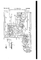
- FIGS 1, 2 and 3 are side elevational views which taken together illustrate a mechanism embodying the instant invention, parts being broken way; 7 I
- Figs. 4 and '5 are top plan views of the mechanism shown in Figs. 2' and 3 respectively with parts broken away;
- Fig. 6 is an enlarged sectional detail taken substantially along the broken line E-6 in Fig. 4, with parts broken away;
- Fig. 7 is a combined schematic view of the mechanical control parts of the mechanism and. a Wiring diagram of the electric apparatus used in the mechanism;
- Fig. 8' is a continuation of Fig. '7;
- Fig. 9 is an enlarged sectional view of one of the mechanical control devices, schematically shown in Figs. "7 and 8.
- the drawings illustrates; mechanism for cutting sheets A (Fig. '1') of sheet material, such as tin plate or the like, into strips B, arranging the strips into stacks, and then distributing the stacks to a plurality of machines such as punch presses, 'bodymakers, or the like, for the forming of container or can parts or other articles from the strips.
- V a plurality of machines
- the sheets A are fed 'fr'om a stack off such sheets retained in a "feeding'machine C (Fig. 1) and are advanced into a slitter, scroll shear or other cutting machine" D' 'where the sheets are cut into strips.
- the shear D discharges the cut strips into a stacker E (Figs. '2' and 6)
- a platiorrn ,F Figs. ';2 and '6- di'sposed above and adjacent a normally stationary and intermittently operated conveyor G;
- the drawings show three loading stations (see Figs. 2 and 3) with their associated magazines H, presses J, and lifter devices K, although the invention is equally well adapted to any number of loading stations as de- A sired.
- the stacks of strips B as they are placed on the conveyor G are ear-marked for a certain loading station; i. e. the first stack for the first station, the second stack for the second station, the third stack for the third station, and then repeating, the fourth stack for the first station, etc.
- the lifter devices K operate in succession in accordance with the order in which the stacks are placed on the conveyor G. Hence when a number one stack reaches the first station (I) it will be lifted into the magazine at such station, while the lifter devices at stations II and III remain idle. Stacks destined for stations II and III will pass the first station and when the stack intended for station II reaches said station, it will be lifted into its magazine H. In a similar. manner a stack intended for station III will also pass station II and when it arrives at station I11, it will be lifted into the magazineH at such locality.
- the mechanism is arranged to cease feeding sheets A and cutting strips B for this machine or magazine so that an over-supply of strips will not be fed to a machine or magazine if it does not demand them.
- a stack of strips already formed for the stopped machine or filled magazine will not be released from the stacker and hence will not be delivered to the conveyor.
- This stack however will be released for the next machine or magazine in the line, providing this machine or magazine is still operating.
- An electric control system is provided for governing this proper distribution of the stacks to the proper machines or magazines. Any stacks of strips on the conveyor will be delivered to theirmachine or magazine whether or not they are operative, since the magazines are designed with sufficient capacity to receive these additional strips without overloading the magazme.
- the sheet feeding machine C which feeds the sheets A to be cut into strips B is a conventional machine of the type for example disclosed in United States Patent 2,074,330, issued March 23, 1937, to V. T. Grover on Sheet Handling and Feeding Apparatus.
- a stack of sheets A which constitutes the supply of sheets is slowly lifted by cooperating pairs of vertically mounted conveyor chains 2
- the suction cups 22 are connected, as disclosed in the above mentioned Grover patent, to a vacuum line or pipe 25 which leads to any suitable source of vacuum. Control of the vacuum supply for feeding or nonfeeding of the sheets A from the stack is obtained through a shut-off valve 25 which is connected to the vacuum pipe 25 and which is opened and closed by an electric solenoid 21 connected therewith.
- the solenoid is normally energized through electric circuits which will be hereinafter explained in connection with the wiring diagram in Figs. 7 and 8, and. thus normally holds the vacuum valve 26 open to permit continuous feeding of sheets.
- a punch press J or its magazine H becomes inoperative, the valve is closed and hence the vacuum is cut oil from the cups 22. Feeding of the sheetsfor the inoperative machine or magazine is thus stopped.
- the scroll shear or cutting machine D is a con-- ventional machine of the type disclosed in United States Patent 1,920,999, issued August 8, 1933, to J. H. Murch on Shearing Machine and includes anendless chain conveyor 3! (Fig. 1) which picks. up the sheet A fed from the feeding machine Ci and advances it into and through the scroll shear D.
- the back edge of the sheet is successively engaged in the usual manner by a plurality of spaced fingers of a reciprocating feed bar which advances the sheet in a step-by-step or intermittent manner between a stationary lower die member 33 (Fig. 1) and a vertically reciprocating upper punch member 34 which onoperate in cutting the sheet A into the strips B as hereinbefore mentioned.
- this scroll shear machine is exemplary and any other cutting or slitting machine may be substituted.
- the individual strips B fall from the forward edge of the die member 33 and are received on a plurality of spaced and parallel continuously moving delivery belts 36 (Figs. 1 and 2) which deliver the strips in spaced and timed order into the stacker E.
- the belts operate over pairs of spaced pulleys 3B. 39 (Figs. 2 and 4) carried in a plurality of brackets M3, tied together by a transverse tie rod M, the ends of which are secured in brackets 42 bolted to a conveyor frame t3 disposed adjacent the shear D.
- the pulleys 38 are mounted on short shafts 45 carried in the brackets 40.
- the .pulleys 39 are mounted on a long drive shaft 48 which extends through all of the brackets 40 and which may be driven in any suitable manner in time with the shear D.
- the stacker E that receives the strips B from the delivery belts 36 includes a plurality of pairs of oppositely disposed L-shaped stack g holding fingers 48, 49 (Figs. 41 and, 6) which cooperate in supporting the. strips in a horizontal position one on top of the other, as they are received from the delivery belts to form a stack.
- These holding fingers are mounted on a pair of spaced and parallel shafts 52 (see also Fig. 2) the ends of which are carried in bearing brackets 5'3 secured to the conveyor frame 43.
- the air cylinder 63 (Fig. 7) adjacent its ends is connected by pipes 65', 66 to a slide valve housing at containing a slide valve r68 having a central feed channel ii-9.
- One end of the valve housing is open. Its opposite end, beyond the slide valve is provided with a vent opening "H. At this vented end of the housing the valve is backed up by a compression spring 12 interposed between the valve and the closed end of the housing.
- the valve housing is connected to an inlet pipe 13' which is always in communication with the central feed channel 69' of the slide valve and which leads from any suitable source of compressed air.
- the slide valve 63 is periodically reciprocated within its valve housing 6.! by a normally deenergized electric solenoid 15 which, is alternately energized and de-energized through suitable. electric circuits which will be hereinafter explained in connection with the wiring diagram. in Figs. 7 and 8.
- the solenoid T5 When the solenoid T5 is energized, it shifts the slide valve -68, from the position shown inF'ig. *7 toward the left as. viewed in thatfigure and thus brings the pipe 65 into communication with the central feed channel 69' of the valve and cuts out the pipe 6%.
- the sections of this platform are secured to asupp ort plate 8i attached to a vertically movable slide- 82- which operates in a vertical slieleway 83 formed; in a transverse bracket E l having its outer ends secured to the conveyor frame 43.
- the slide is periodically lowered and raised by a bell crank lever 85 which is mounted on a pivot pin 86 carried in a bracket Bl secured to two of a plurality of longitudinal chain rails 88 bolted to cross beams 8901? the conveyor frame.
- the other leg is connected to a piston rod Q2 having a piston $3 (seeFigs. 7 and 9) which operates in a cylinder 94 of a conventional oil. gear system which circulates oil or any other suitable fluid under pressure through the. system.
- the cylinder 9t. adjacentzits ends isv connected by oil pipes, 55.; 96'- to a valve housing 91 containing a reciprocable slide valve 93,. havinga central feed port 99 and apair of endv vent ports Nil, 582.
- valve housing 5-? Opposite the pipes 95, 96 the valve housing 5-? is connected. by an inlet pipe- I- to a main feed pipe 199 which leads from a suitable source of oil or other fluid medium under pressure.
- the valve end of the inlet pipe 10.5 is always in communication with the feed port 99 of the slide valve.
- This side of the, valve. housing is also formed, with a pair of vent channels lii'i, I58 which are in communicationv with a pair of connecting vent pipes I99, H9. connected with a main return pipe- H-l. whichleads to. any suitable place of discharge or reuse of the. circulated. oil.
- the slide valve 93 is reciprocated in its housing 9? by a pair of normally (lo-energized electric solenoids H5, H5 which arev alternately energized and tie-energized by suitable electric circuits which will be hereinafter explained in con nection with the wiring diagram in. Figs. 'Tand 8.
- H5 normally (lo-energized electric solenoids H5, H5 which arev alternately energized and tie-energized by suitable electric circuits which will be hereinafter explained in con nection with the wiring diagram in. Figs. 'Tand 8.
- H5 When the solenoid H5 isenergized it shifts the slide valve 98 from the position shown in Fig. 9 to a position toward the left where the oil pipe 95. is in communication with the valve feed 99.
- valve 98. With the valve 98. in. this position, oil under pressure from the main feed pipe Hi6 and the inlet pipe I95 flows through the valve port as and pipe 95 into the cylinder 95 behind the piston es and thus pushes the piston toward the right as viewed in Fig- 9. Any used oil which is in the cylinder in front of the piston is pushed out through the pipe 96, aligned valve vent port i652, vent channel Hi8 and pipe. Hi1 into the main return pipe Hi. This movement of the piston carries the platform 18 and its stack of strips B down into a lowered or stack: delivery position.
- the platform 18 returns or moves up into its original position in readiness for the reception of the next following or subsequent stack. This return movement of the platform is effected by the energization of the electric solenoid I I6.
- the conveyor G which receives and advances the stocks of strips B comprises a plurality of endless chains I2I (Figs. 2, 3, 4 and 5) which are disposed in spaced and parallel side by side relation and carry short stack supporting flats or treads I22 which provide a continuous table or support for the stacks of strips.
- the chains extend for the full length of the conveyor frame 43, along a straight line path of travel past the three punch presses J and their associated magazines H.
- These chains operate over idler sprockets I24 located at the receiving end of the conveyor (at the left as viewed in Figs. 2 and 4) and over driving sprockets I25 (Figs. 3 and 5) located at the opposite end of the conveyor.
- the idler sprockets I24 are mounted on idler shafts I25 while the driving sprockets are mounted on driving shafts I27. These shafts are carried in bearings formed in the conveyor frame 43. Between the sprockets the upper runs of the chains operate along and are supported against sagging, by the longitudinal chain rails or tracks 88 hereinbefore mentioned. There is one of these tracks for each chain.
- the conveyor chains I2I are operated in unison in an intermittent or step-by-step manner by an actuating device which includes an actuating chain 3i (Figs. 3 and 5).
- This chain operates over a sprocket I32 carried on the outer end of the conveyor driving shaft I27 and over a sprocket I33 which is mounted on a stub shaft I34 carried in a bearing in a plate I35 bolted to the side of the conveyor frame 43.
- the chain carries a plurality of actuating dogs I37 secured thereto at spaced intervals.
- the slide block I39 is periodically reciprccated in its slideway id! for shifting the actuating chain 23! and the conveyor G connected therewith.
- the slide block is connected to a piston rod E44 having a piston which operates in a cylinder I45 (Fig. 8) which in construction and operation is similar to the platform actuating cylinder 94 shown in Fig. 9.
- This cylinder I45 is part of the oil gear system hereinbefore mentioned and is connected by oil pipes I48, I4! (Fig.
- a slide valve housing I48 similar to the valve acaasoa housing 91.
- the housing in turn is connected by an inlet pipe I49 to the main feed pipe I06 and by outlet or vent pipes I50, I5I to the main return pipe III.
- Oil is circulated through the cylinder I45 for moving the slide block I39 through a conveyor actuating stroke and then through a return stroke, by a slide valve which is retained within the housing I48 and which is shifted into its operating positions by a normally de-energized electric solenoid I54 (Fig. 8) which is alternately energized and de-energized by suitable electric circuits which will be hereinafter explained in connection with the wiring diagram in Figs. 7 and 8.
- the slide valve is similar in construction and operation to the platform actuating slide valve 93 shown in Fig. 9.
- the actuating finger IE8 On the return stroke of the piston rod I44 and the slide block I39 connected therewith, the actuating finger IE8 is pushed back into its original position in front of the next actuating dog I31 for a subsequent advancement of the conveyor G. During this return stroke of the actuating finger I38, the actuating chain I3I and the conveyor G remain stationary. The actuating finger, due to its spring mounting snaps under the actuating dog I37 without moving the chain to which it is connected.
- the magazines H which receive the stacks of strips B from the conveyor G are located at spaced intervals along and above the path of travel of the conveyor and are disposed transversely of the conveyor in an inclined position as shown in Figs. 2, 3, 4 and 5.
- These magazines are defined by hollow rectangular shaped frames IGI open at top and bottom and having laterally extending lugs I62 formed on their lower edges and bolted to the conveyor frame 43 for holding the magazine frames in place.
- the upper edges of the magazine frames are secured to upright brackets IE3 which are bolted to the conveyor frame 43.
- Spring held support fingers I65 (Fig. 3) pivotally mounted in the magazine frames along their upper and lower edges project into the magazines and retain the stacks of strips B in place as they are received in the magazines.
- the stacks of strips B are inserted into the magazines H through their open bottoms by the lifter devices K which are disposed under the magazines and just below the path of travel of the stack supporting treads I22 of the conveyor G.
- the swinging movement of the lifter pads IE3 is effected preferably by an actuating arm I15 (see Fig. 3) which is mounted on and rocks the pivot shaft I10.
- the outer end of the actuating arm is connected by a link I16 to a reciprocable slide block I'll which operates in a horizontal slideway Ill; formed in a bracket I19 bolted to the side of the conveyor frame 43.
- the slide block. IT! is periodically reciprocated in its slideway I18 for rocking the actuating arm I75 and for this purpose it is connected to the outer end of a piston red It] having a piston which operates within a cylinder I82 which in construction and operation is similar to the platform actuating cylinder 94 shown in Fig. 9. There is one of these cylinders I82 for each lifter device K and each cylinder is part of the oil gear system hereinbefore mentioned.
- Each cylinder I82 is connected by oil pipes 18c, H35 (Fig. 8) to a slide valve housing sea The housing in turn is connected by an inlet pipe it! to the main feed pipe 16-6 and by outlet or vent pipes I56, I89 to the main return pipe II I. Oil is circulated through the cylinders I82 for moving the slide block I'll through a lifter working stroke and then through a return stroke by a slide valve which is retained within each of the housings I86 and which in construction and op eration is similar to the platform actuating slide valve 93 shown in Fig. 9.
- the slide valves in the valve housing I86 are shifted into their operating positions independently of each other and in proper sequence by normally de-energized electric solenoids which are energized and de-energized by suitable electric circuits which will be hereinafter explained in connection with the wiring diagram in Figs. 7 and 8.
- the slide valve for the first lifter deice K is controlled by a solenoid lei (Fig. 8).
- the second lifter device is controlled by a separate solenoid 92 and the third lifter device is controlled by another solenoid I93.
- Inserting of the stacks of strips B into the magazines H through their open bottoms leaves the top of the magazine free and clear so that the strips may be fed individually from the top of the stack without interfering with the insertion of additional strips from the bottom to maintain a normal supply of strips in the magazine.
- Feeding of the strips from the magazine into the punch press J associated with each magazine may be effected in any suitable manner preferably as disclosed in the above mentioned Schoendelen patent.
- the punch presses are shownv equipped with suction cups I95 for this purpose.
- Figs. 7 and 8 discloses schematically the various electric circuits which control the operation of the various solenoids hereinbefore mentioned, and which transmit electric current from any suitable source of supply, such as an electric generator 230, having a lead wire it! and a main return wire .262. These circuits are established at the proper time and in a predetermined sequence in accordance with the 10 formation of the stacks of strips B and the demand of the presses J for the stacks.
- Each stack contains the strips cut from a predetermined number of sheets A. As for example, ten sheets when out into may constitute one stack. If each sheet is out into three strips, there will be thirty strips in a stack. If a sheet is cut into five strips, each stack will have iiity strips. Therefore the size of the stack depends upon how many strips are out from each sheet, the scroll shear D being set to cut the particular width of strip required, and the control of the entire mechanism being governed in accordance with the period of time required to feed the ten sheets to produce one unit stack of strips.
- This control of the mechanism is governed primarily by a stack release cam 23% (Figs. 2, i and '3') and a set of three timing cams 236, 26?, 288 which are continuously rotated through a driving connection with the scroll shear D.
- the stack release cam makes one revolution for each stack of strips formed in the stacker i. o. one revolution for each ten sheets fed from the feeding machine C.
- the release can: 29-5 is mounted on a continuously rotating shaft 2H] journaled in bearings formed in the frame of the scroll shear I) (see Fig. 2)
- the shaft 2 Iii is rotated by a gear 2 I i which is mounted on the shaft and which is driven through a speed reducing train of meshing gears 52 I2, 2213, Eli, 2 iii, iiili rotatably-carried in a gear housing 2.1! secured to the convoy r frame
- the gear 2 It is mounted on a driving shaft 25 8 (see Fig. i) which extends across the front of the scroll shear D and which is continuously rotated in any suitable manner, preferably through. a sprocket and endless chain connection 2 It with the scroll shear,
- timing cams 2G5, 25W, 288 each make one third of a revolution for each full revolution of the stack release cam 265.
- 1e timing cams 285$, till, 2% are mounted on a continuously rotating shaft 225 which is journaled in bearings formed in the frame of the scroll shear D (Fig. 2). ihe shaft is rotated by a gear 222 which is mounted on the shaft and which is driven by a meshing speed reducing gear 223 which meshes with and is driven by the release cam shaft gear 2% i.
- the gear 223 is carried on a shaft 22% which is journaled in the frame of the scroll shear.
- the sheets A are fed continuously, one after the other, from the sheet feeding machine 0 by continuous operation of the suction cups 222, the vacuum valve 26 in the vacuum line 25 being maintained in an open condition by continuous energization of the valve solenoid 2?.
- a vacuum valve circuit N (Fig. 7) which includes the solenoid El.
- one side of the solenoid is connected by a wire 2% to the main lead wire 28! of the generator
- the other side of the solenoid is connected by a wire 232 to a normally closed switch 233.
- the switch is also connected in series by a wire 2% to a second normally closed switch 235 and this in turn is connected in series by a wire 235 to a third normally closed switch 232? which is connected by a wire 233 to the main return wire 282 of the generator.
- Electrio current flowing along this circuit when all 1 1 of the switches are closed, maintains the solenoid 21 in an energized condition.
- a normally closed electric press switch 24I (Fig. 8) which may be opened and closed by any suitable part of the press or may be actuated by the strips as they build up in the magazine H of the press, Whichever may be more convenient or more desirable, since both are equally well adapted to perform this function.
- the press switch 24I and a normally open electric timing switch 242 actuated by the timing cam 205 corresponding to press No. I, together with a normally open release switch 243 operated by the stack release cam 205 are included in a release circuit which also includes the air cylinder solenoid I5.
- the timing switch 242 and the release switch 24 3 are closed simultaneously and momentarily by their respective cams 206, 205.
- the energizing of the air cylinder I5 is also of a momentary nature and hence the stack holding fingers 48, 49 open and close rapidly to permit of the immediate formation of a stack of strips B for the next press in the line; in this case press No. 2, as soon as the stack for press No. I has been released.
- a circuit P which includes the delivery platform actuating solenoid II5.
- one side of the solenoid is connected by a wire 252 to the generator main lead wire 20L
- the opposite side of the solenoid is connected by a wire 253 to a normally open electric switch 254 which is connected by a wire 255 to the generator return Wire 202.
- the conveyor and its stack is advanced one step. Advancement of the conveyor is brought about through establishment of a conveyor circuit R- which includes the oil cylinder solenoid Q54 and a normally open control switch 259 which is momentarily closed by a cam 259 mounted on the release cam shaft 2H] and rotated in time with the release cam 205.
- a conveyor circuit R- which includes the oil cylinder solenoid Q54 and a normally open control switch 259 which is momentarily closed by a cam 259 mounted on the release cam shaft 2H] and rotated in time with the release cam 205.
- the switch 258 is closed, current from the generator lead wire 20I flows along a connecting wire 20L solenoid I54, 2. wire 262, closed switch 258, and a Wire 203 returning to the generator return wire 202.
- This current energizes the solenoid I54 which controls the movement of the conveyor actuating device through its oil cylinder I45.
- the control switch 258 remains closed for a period sufficient to permit a full stroke of the piston rod 144
- the slide block 30 engages and closes a normally open electric switch 205 which is part of a circuit S which includes the oil cylinder solenoid H6 which returns the platform I8 to its up or original position for the reception of the stack No. 2 which has been forming during the above explained operations. Closing of the switch 205 permits electric current to flow from the generator lead wire 205 along a Wire 255, solenoid II6, a wire 261, a connecting wire 208, closed switch 265, and returning along a wire 269 to the generator return wire 202.
- the stepped or intermittent advancement of the conveyor G takes place at regular timed intervals under the control of the rotating cam 259 and makes one step or advancement every time the cam makes one revolution, whether or not a stack of strips is released from the stacker E.
- the conveyor Under normal operation of the mechanism, as when all of the presses J are operating and using the strips fed to them, the conveyor receives a stack every time it makes one advancement and thus carries the proper stack to the proper press for insertion into its magazine H.
- the stack When a No. I stack arrives adjacent the magazine H of the No. I press, the stack is inserted into the magazine by its lifter device K which is controlled by the solenoid ISI.
- the solenoid For this lifting operation the solenoid is energized only when a No. I stack is in position at the loading station of the No. I press and the lifting is efiected only while the switch 205 of conveyor actuating device is closed so that proper timing may be had.
- the energization of the solenoid is controlled through a lifter circuit T which includes a normally open switch 2' which is closed at the proper time by the rotating timing cam 200.
- the timing switch 27! is used to assure operation of only that lifter device K which is associated with the No. I press and to cut out the other lifter devices for the other presses. This completes the controlled cycle of operation of the mechanism for stacks of strips B intended for press No. I.
- Control of the mechanism for stacks of strips intended for the other two presses in the line is eifected in the same manner by additional circuits which will be now briefly described.
- the release of a stack of strips from the stacker E for press No. 2 is effected through the release circuit in a manner similar to that used for press No. I but with the exceptions that the circuit now will include a normally closed electric press switch 215 which is similar to switch 241 and which is associated with press No. 2 or its magazine H, and also includes a normally open timing switch 215 operated by the press No. 2 timing cam 207.
- press No. 2 is operative, as indicated by its closed press switch Eli), when the release switch 243 and the timing switch 276 momentarily close, electric current will flow from wire 2&8 of circuit 0 along connecting wires Ell, 2 through closed timing switch 2%, a wire 279, through closed press switch 21 5, and returning along a connecting Wire 2853 to the generator return wire 202.
- Electric current flowing along this modified circuit 0 energizes the air cylinder solenoid l5 as before and thus opens the stack holding fingers it, it to effect the release of a stack No. 2 for press No. 2.
- press No. 3 is operative, as indicated by its closed press switch 283.
- the release switch 243 and the timing switch 283 momentarily close electric current will flow from wire 248 of circuit 0 alon connecting wires Zll, 296, through closed timing switch 283, a wire 291, through closed press switch 288, and returning along a connecting wire 292 to the generator return wire 202.
- Electric current flowing along this modified circuit 0 energizes the air cylinder solenoid it as before and thus opens the stack holding fingers 48, 49 to effect the release of a stack No. 3 for press No. 3.
- cam actuated switches 242 and 253 periodically close simultaneously and if magazine stack switch 2 is also closed at such time, stack holding fingers 6B, 49 are automatically retracteto drop a stack of strips to the platform 13, which is thus actuated to deliver said stack to the conveyor G earmarked for delivery to the magazine H in the first or No. I punch press J in the line.
- cam actuated switches 215 and 243 close periodically simultaneously and if magazine stack switch 275 is closed at such time, said stack holding fingers are retracted to release a stack to the platform earmarked for delivery to the No. 2 press magazine H by conveyor G. Also cam actuated switches 289 and 243 close simultaneously, and in the event magazine switch 288 is closed at such time, such stack holding fingers are retracted to drop a stack to the platform 18 carmarked for the No. 3 press magazine.
- press No. becomes inoperative, its switch 24! immediately opens and this prevents establishment of the release circuit O for this press as long as the press remains inoperative.
- the opening of the switch 24! also prepares for establishment of a devacuumizing circuit W which will break the vacuum valve circuit N at the proper time and thereby prevent the feeding of any more sheets A for the inoperative press.
- This devacuumizing circuit W includes a pair of auxiliary contacts 30f associated with the press switch 24! and an auxiliary timing switch 302 associated with the No. timing switch 242 operated by cam 205.
- a holding circuit is provided to hold the solenoid 308 energized and the switch 233 open for a period equal to that required to feed sufficient sheets for one stack so that a new stack will be prevented from being formed as long as the stack already in the stacker E is held against release.
- This holding circuit is formed through a normally open switch (H2 and a pair of contacts 3l3 associated with the switch 233. When the movable element of switch 233 shifts to open the switch, it immediately closes against the contacts 3!3 and also closes the switch 3 2.
- this holding circuit is broken by the opening of the breaker switch 3
- the vacuum valve circuit N is held broken for the stack forming cycle for press No. 2 by a holding circuit which includes a normally open switch 335 and a pair of contacts 338 associated with the switch 235.
- a holding circuit which includes a normally open switch 335 and a pair of contacts 338 associated with the switch 235.
- the vacuum valve circuit N is held broken for the stack forming cycle for press No. 3 by a holdin circuit which includes a normally open switch 35! and a pair of contacts 352 associated with the switch 231.
- a holdin circuit which includes a normally open switch 35! and a pair of contacts 352 associated with the switch 231.
- the movable element of switch 23? shifts to open the switch it immediately closes against the contacts 352 and also closes the switch 35 I
- electric current from the generator lead wire Edi flows along the connecting wire 315, through the breaker switch 3H1 and connecting wire 3H5, a wire 353, closed switch 35I, wires 354, 355, 3 5, solenoid 353, a wire 356, closed contacts 352, a wire 35'! and wire 238 back to the generator return wire 282, Current flowing along this circuit maintains this solenoid 346 energized after the auxiliary timing switch 343 opens.
- this holding circuit is broken by the opening of the breaker switch 3H3 through the rotation of the cam 3H. This immediately de-energizes the solenoid 343 and thus closes the switch 231 in the vacuum valve circuit N and opens the contacts 252 and switch 35L The closing of the switch 23? immediately re-establishes the vacuum valve circuit N and resumes feeding of sheets A to provide stacks for the operative presses No. l and 2 or for any one press if this alone is operative as hereinbefore explained. This completes the entire cycle of operations of the electric control devices.
- Mechanism for loading stacks of sheets into the supply magazines of a plurality of machines in accordance with the demands of those inachines comprising a movable conveyor for advancing successive stacks of sheets, a stack support movably mounted adjacent said conveyor for receiving the stacks of sheets and for delivering the same to said conveyor, a plurality of magazines for said sheets to supply the demands of machines connected therewith, said magazines being disposed in spaced relation along the path of travel of said conveyor for receiving said stacks of sheets therefrom, means disposed adjacent each of said magazines for inserting individual stacks thereinto from said conveyor, means for movin said stack support towards and away from said conveyor for normally delivering successive stacks to the conveyor in substantially the order of delivery to said magazines, and control means operable upon said stack support moving means in accordance with the demand of each of said machines and its magazine to stop delivery of a stack to said conveyor whenever a magazine normally destined to receive that stack is filled and there is thus no demand for the stack.
- Mechanism for loading stacks of sheets into the supply magazines of a plurality of machines in accordance with the demands of those machines comprising a movable conveyor for advancing' successive stacks of sheets, a stack support movably mounted above said conveyor for receiving successive stacks of sheets and for delivering the same to said conveyor, a plurality of magazines for said sheets for respectively supplying the demands of machines connected therewith, said magazines being disposed in spaced relation above the path of travel of said conveyor for receiving said stacks of sheets therefrom, a lifter member movably mounted beneath each of said magazines for elevatin individual sheet stacks thereinto from said conveyor, fiuid pressure means for vertically reciprocating said stack support towards and away from said conveyor for normally delivering successive stacks to the conveyor in substantially the order of delivery to said magazines, and cam actuated control means operable upon said fluid pressure means in accordance with the demand of each of said machines and its magazine to stop delivery of a stack to said conveyor whenever a magazine normally destined to receive that stack is filled and there is thus no demand for the stack.
- Mechanism for loading sheets into the magazines of a plurality of machines for subsequent feeding therefrom comprising a movable conveyor for receiving and advancing successive stacks of sheets, stack supporting means movably mounted above said conveyor for receiving stacks of sheets and for delivering the sam to said conveyor, a plurality of magazines for said machines disposed in spaced relation along the path of travel or said conveyor for receivin said stacks of sheets therefrom, means disposed adjacent each of said magazines for inserting individual stacks thereinto from said conveyor, means for moving said stack supporting means for normally delivering successive sheet stacks to the conveyor in the order of the spaced arrangement of said magazines longitudinally of the conveyor, and
- control means operable upon said stack support moving means in accordance with the demand of the individual magazines for additional sheets for holding a supported stack for a filled magazine against delivery to said conveyor and for delivering said held stack to said conveyor for an unfilled magazine.
- Mechanism for loading sheets into the magazines of a plurality of machines for subsequent feedin therefrom comprising a movable conveyor for receiving and advancing successive stacks of sheets, movable fingers above said conveyor for supporting and releasing successive stacks of sheets, a vertically reciprocable platform disposed beneath said fingers for receiving said stacks therefrom and for delivering the stacks to said conveyor, a plurality of magazines disposed in spaced relation along and above said conveyor for receiving said stacks of sheets therefrom for delivery to said machines, means disposed beneath each of said magazines for elevating individual stacks thereinto from said conveyor, means for moving said fingers to release a stack of sheets to said platform, means for vertically reciprocating said platform towards and away from said conveyor for normally delivering successive sheet stacks to the conveyor earmarked for said magazines in the order of the arrangement of the magazines longitudinally of the conveyor, and control means operable upon said finger moving means in accordance with the demand of the individual magazines for additional sheets for holding said fingers against release and delivery of a stack to said conveyor for a filled magazine, said control means being further
- Mechanism for loading sheets into the magazines of a plurality of machines for subsequent feeding therefrom comprising an intermittently movable conveyor for receiving and advancing successive stacks of sheets, a plurality of fingers movably mounted above said conveyor for receiving and supporting successive stacks of sheets destined for delivery to said conveyor, a platform mounted for vertical movement relative to said conveyor for receiving said successive sheet stacks when released by said fingers, means for moving said fingers in timed relation with the intermittent movement of said conveyor normally to release successive stacks of sheets to said platform, a plurality of magazines for said machines disposed in spaced relation above the path of travel of said conveyor for receiving said stacks of sheets therefrom, means actuated by the movement of said fingers to stack releasing position for vertically moving said platform towards said conveyor to successively deliver said stacks thereto, means movably mounted adjacent each of said magazines for elevating individual sheet stacks thereinto from said conveyor, and cam actuated control means operable upon said stack supporting fingers in accordance with the demand of the individual magazines for additional sheets for holding a supported stack earmarked for a filled magazine
- Mechanism for loading sheets into magazines of a plurality of machines for subsequent feeding therefrom comprising a movable constacks of sheets, stacks supporting means movably mounted above said conveyor for receiving stacks of sheets and for delivering the same to said conveyor, a plurality of magazines for said machines disposed in spaced relation along the path of travel of said conveyor for receiving said stacks of sheets therefrom, a normally closed demand switch adjacent each of said magazines and opened by a high stack therein when there is no demand for replenishment of the magazine associated therewith, lifter means disposed adjacent each of said magazines for inserting individual stacks thereinto from said conveyor, a lifter actuating means including a lifter solenoid adjacent each of said lifter means, a plurality of normally open lifter switches each electrically connected in an energizing circuit with a said lifter solenoid, means including a stack release solenoid for moving said stack supporting means for normally delivering successive sheet stacks to the conveyor in the order of the spaced arrangement of said magazines longitudinally of the conveyor, a normally open stack
- a mechanism for loading sheets of material into magazines for subsequent feeding therefrom comprising a plurality of ma azines arran ed in consecutive order for receiving and holding st cks of sheets of material.
- con e r means extending along a path of travel past said magazines, means for delivering to said con evor in spaced and timed relation stacks of sheets consecutively arran ed in the order of said ma azines, means for intermittently ad ancin said.
- electric ontrol means operable in time with the deli ery of said stacks of sheets to said conveyor for controlling the advancement of sa d conveyor.
- inserting means disposed ad acent each of said ma az nes for insertin into said ma azines the stacks of sheets intended for e ch ma azine. and e ectric. means for each of sa d ma azines f r nul ifv n the ct on of said ele tric control means for holding a stack of sheets against delivery to said conveyor for advancement to a predetermined magazine until that magazine is in condition to receive a stack of sheets.
- a mechanism for loading sheets of m terial into magazines for subseouent feeding therefrom comprising a plurality of magazines arranged in consecutive order for receiving and holding stacks of sheets of material, conveyor means extending along a path of travel past said magazines, means disposed adjacent said conveyor for feeding individual sheets of material and for arranging them into stacks, means for delivering to said conveyor in paced and timed relation stacks of sheets consecutively arranged in the order of said magazines, means for intermittently advancing said conveyor means for positioning said stacks of sheets adjacent said magazines in the proper order, electric control -means operablein time with the delivery of said 1 stacks of sheets to said conveyor for controlling the advancement of said conveyor, inserting means disposed adjacent each of said magazines for inserting into said magazines the stacks of sheets intended for each magazine, electric means for each of said magazines for nullifying the action of said electric control means for holding a tack of sheets against delivery to said conveyor for advancement to a predetermined magazine when that magazine is filled with sheets, and electric means governing the feeding of said sheets and controlled by
- Mechanism for loading sheets into the magazines of a plurality of machines for subsequent feeding therefrom comprising a movable conveyor for receiving and advancing successive stacks of sheets, a stacker located above said conveyor for supporting and releasing successive stacks of sheets, a stack support movably mounted beneath said stacker for receiving said stacks therefrom and for delivering the stacks to said conveyor, a plurality of magazines disposed in spaced relation along and above said conveyor for receiving said stacks of sheets therefrom for delivery to said machines, means disposed beneath each of said magazines for elevating indi-- vidual stack thereinto from said conveyor, means for actuating said stacker to release a stack of sheets to said stack support, means for moving said stack support towards and away from said conveyor for normally delivering successive sheet stacks to the conveyor earmarked for said magazines in the order of the arrangement of the magazines longitudinally of the conveyor, and control means operable upon said stacker actuating means in accordance with the demand of the individual magazines for additional sheets for holding said stacker against release and delivery of a stack to said conveyor for
- Mechanism for loading stacks of sheets into the supply magazines of a plurality of machine in accordance with the demands of those machines comprising a movable conveyor for advancing successive stacks of sheets, a stack forming device located adjacent said conveyor for forming a stack of a pre-determined number of sheets, feeding means located adjacent said stack forming device for feeding individual sheets to said stack forming device to form said stacks, a stack support movably mounted adjacent said conveyor for receiving the stacks of sheets from said stack forming device and for delivering the same to said conveyor, a plurality of magazines for said sheets to supply the demands of machine connected therewith, said magazines being disposed in spaced relation along the path of travel of said conveyor for receiving said stacks of sheets therefrom, means disposed adjacent said magazines for inserting individual stacks thereinto from said conveyor, means for moving said stack support towards and away from said conveyor for normally delivering successive stacks to the conveyor in substantially the order of delivery to said magazines, and control means operable upon said feeding means for stopping the operation thereof in accordance with the demand of each of said machines and its
- Mechanism for loading stacks of sheets into the supply magazines or" a plurality of machines in accordance with the demands of those machines comprising a movable conveyor for advancing successive stacks of sheets earmarked for certain magazines, a stack support movably mounted adjacent said conveyor for receiving the stacks of sheets and for delivering the same to said conveyor, a plurality of magazines for said sheets to supply the demands of machines connected therewith, said magazines being disposed in spaced consecutive order along the path of travel of said conveyor for receiving said stacks of sheets therefrom, means disposed adjacent each of said magazines for removing from said conveyor and for inserting into each magazine its proper stack of sheets, means for moving said stack support towards and away from said conveyor for delivering stacks of sheets to said conveyor in the earmarked order for conveyance to said magazines, and control means operable upon said inserting means individually and independently of each other for inserting into each magazine only the stack of sheets earmarked for that magazine.
Landscapes
- Engineering & Computer Science (AREA)
- Mechanical Engineering (AREA)
- Discharge By Other Means (AREA)
Description
Feb. 24, 1953 c. G. PREIS ETAL MECHANISM FOR LOADING SHEET MATERIAL INTO MAGAZINES Filed Aug. 5, 1947 7 Sheets-Sheet l 2 w N 0 B r E \N o I a \m u MM 0 o 0 WW 0 0 o 0 MN. 0 0 mm. I 1| Wm T NW Q R, o W L N u M. n $$u k l wuquow ok J n K 4/ \N b S Y E N R O T JA Feb. 24, 1953 c. G. PREIS ETAL MECHANISM FOR LOADING SHEET MATERIAL INTO MAGAZINES Filed Aug. 5, 1947 7 Sheets-Sheet 2 7'0 FIE-l ATTORNEYS MNN 2 ANN NM kw Rm mm h Feb. 24, 1953 c. aPREIs ETAL MECHANISM FOR LOADING SHEET MATERIAL INTO MAGAZINES Filed Aug. 5, 1947 7 Sheets-Sheet 3 a NWN j T N Z Tor/6.2 E g Feb. 24, 1953 c. G. PREIS ETAL MECHANISM FOR LOADING SHEET MATERIAL INTO MAGAZINES Filed Aug. 5, 1947 7 Sheets-Sheet 4 I I l I |l| NVENTORS ATTO RN EYS Feb. 24, 1953' v 2,629,502
MECHANISM FOR LOADING SHEET MATERIAL INTOIAGAZINES c. G. PREIS El AL Feb. 24,1953 c. G. PREIS ET AL 2,629,502
MECHANISM FOR- LOADING SHEET MATERIAL INTO MAGAZINES Filed Aug. 5, 1947 7 Sheets-Sheet 6 Feb. 24, 1953 C. G. PREIS ETA].
MECHANIS" FOR LOADING SHEET MATERIAL INTO MAGAZINES Filed Aug. 5, 194'? 7 Sheets-Sheet 7 INVENTORS Z J a Patented Feb. 24, 1953 MECHANISM FOR LOADINGSHEET MATERIAL INTO MAGAZINES Carl G. Preis, Forest Hills, N. Y., and Ronald E. J. Nordquist, Maplewood, N. J assignors to American Can Company, New York, N. Y., a corporation of New Jersey Application August 5, 1947, Serial No. 766,343
11 Claims.
The present invention relates to a mechanism for lOEl-dlllg sheet material into magazines for subsequent feeding therefrom and has particular reference to distributing stacks of sheets of material to a plurality of magazines in accordance with the demand or operating conditions of the magazines. This is a companion application to our copending United States applications Serial Number 7'66,3 i0,'fi1ed August 5, 1947, on Mechanism for Stacking Sheet Material, and Serial Number 766,341, new Patent No. 2,59 l,346 issued April 29, 1952, filed August 5, 1947, and Serial Number 766,342,1iled August 5, 1947, on Mechanism for Loading Sheet Material into Magazines, now Patent No. 2,542,055, issued February 20, 1951.
An object of the invention is the provision of a mechanism for loading sheet material into magazines wherein a plurality of machines using sheet material for the forming of can parts or other articles therefrom and having magazines holding a supply of the material used, may be constantly supplied with the material in accordance with the demand of the magazines so that the machines may be maintained in continuous operation.
Another object is the provision of such a mechanism wherein the distribution of the material to the magazines of the various machines is controlled in accordance with the demand or operating conditions of the machines in such a manner that the stopping 'Of one machine or the filling of a magazine :to capacity will cease feeding of additional material to that machine or magazine Without in any manner affecting the operation of other machines which are still operating or other magazines which are not filled to capacity.
Another object is the provision of such a mechanism wherein the control of the distribution of the material to the magazines or the various machines, is carried back to the source of supply of the material so that the material at its source of supply is earmarked for a particular magazine or machine and when a machine ceases to operate or a magazine is filled to capacity, no material from the source of supply will be advanced for that machine or magazine. This prevents the advancement of material 'for which there is no place of deposit.
Another object is the provisionof such a mechanism wherein sheet material may be cut into strips or blanks and arranged in stacks ofa predetermined number of strips or blanks and the stacks supplied to a plurality of machines or 2 magazines in accordance with their demand for material, the material being handled rapidly and eiiiciently without excessive speed of operation of the mechanism and hence with less wear and tear on the mechanism.
Numerous other objects and advantages of the invention will be apparent as it is better understood from the following description, which, taken in connection with the accompanying drawings, discloses a preferred embodiment thereof.
Referring to the drawings:
Figures 1, 2 and 3 are side elevational views which taken together illustrate a mechanism embodying the instant invention, parts being broken way; 7 I
Figs. 4 and '5 are top plan views of the mechanism shown in Figs. 2' and 3 respectively with parts broken away;
Fig. 6 is an enlarged sectional detail taken substantially along the broken line E-6 in Fig. 4, with parts broken away;
Fig. 7 is a combined schematic view of the mechanical control parts of the mechanism and. a Wiring diagram of the electric apparatus used in the mechanism;
Fig. 8' is a continuation of Fig. '7; and
Fig. 9 is an enlarged sectional view of one of the mechanical control devices, schematically shown in Figs. "7 and 8.
As a preferred embodiment of the invention the drawings illustrates; mechanism for cutting sheets A (Fig. '1') of sheet material, such as tin plate or the like, into strips B, arranging the strips into stacks, and then distributing the stacks to a plurality of machines such as punch presses, 'bodymakers, or the like, for the forming of container or can parts or other articles from the strips. V
The sheets A ,are fed 'fr'om a stack off such sheets retained in a "feeding'machine C (Fig. 1) and are advanced into a slitter, scroll shear or other cutting machine" D' 'where the sheets are cut into strips. The shear D discharges the cut strips into a stacker E (Figs. '2' and 6) When a predetermined number of strips have been collected into a stack; they are deposited on a platiorrn ,F (Figs. ';2 and '6)- di'sposed above and adjacent a normally stationary and intermittently operated conveyor G;
Upon the reception of a stack of strips 13' on the platform F, the platform moves down toward the conveyor G and gently deposits the stack on the" conveyor. {The conveyor is then actuated through a single step movement and thus advances the =-stack-in to an idle station.
Repeated movements of the conveyor as each stack is deposited thereon advances a stack already on the conveyor, in a step-by-step manner through a plurality of idle stations and then brings the stack into a loading station. There are a plurality of these loading stations located along the path of travel of the conveyor G and at each loading station there is a magazine H disposed above the conveyor and associated with a punch press J or other machine for further operating upon the strips B. Each loading station is also provided with a lifter device K which is disposed adjacent the conveyor and which operates to lift the stacks of strips B into the magazines.
By way of example, the drawings show three loading stations (see Figs. 2 and 3) with their associated magazines H, presses J, and lifter devices K, although the invention is equally well adapted to any number of loading stations as de- A sired. The stacks of strips B as they are placed on the conveyor G are ear-marked for a certain loading station; i. e. the first stack for the first station, the second stack for the second station, the third stack for the third station, and then repeating, the fourth stack for the first station, etc.
The lifter devices K operate in succession in accordance with the order in which the stacks are placed on the conveyor G. Hence when a number one stack reaches the first station (I) it will be lifted into the magazine at such station, while the lifter devices at stations II and III remain idle. Stacks destined for stations II and III will pass the first station and when the stack intended for station II reaches said station, it will be lifted into its magazine H. In a similar. manner a stack intended for station III will also pass station II and when it arrives at station I11, it will be lifted into the magazineH at such locality.
When a machine J or a magazine H becomes inoperative, i. when the machine stops operating or the magazine is filled with its maximum supply of strips, the mechanism is arranged to cease feeding sheets A and cutting strips B for this machine or magazine so that an over-supply of strips will not be fed to a machine or magazine if it does not demand them. In such a case a stack of strips already formed for the stopped machine or filled magazine will not be released from the stacker and hence will not be delivered to the conveyor. This stack however will be released for the next machine or magazine in the line, providing this machine or magazine is still operating. An electric control system is provided for governing this proper distribution of the stacks to the proper machines or magazines. Any stacks of strips on the conveyor will be delivered to theirmachine or magazine whether or not they are operative, since the magazines are designed with sufficient capacity to receive these additional strips without overloading the magazme.
For the purposes of this specification a machine J and its magazine H are considered as a unit since normally the magazine is a part of the machine as for example disclosed in United States Patent 1,443,761, issued January 30, 1923, to H. Schoendelen on Safety Devices for Punch Presses and the Like. Hence when the machine stops operating, no strips are fed from the magazine, although as sometimes arranged, feeding of the strips from the magazine may be prevented while the machine operates without performing any workas. during anidle period.
A detailed description of the mechanism now follows: The sheet feeding machine C which feeds the sheets A to be cut into strips B is a conventional machine of the type for example disclosed in United States Patent 2,074,330, issued March 23, 1937, to V. T. Grover on Sheet Handling and Feeding Apparatus. In this machine a stack of sheets A which constitutes the supply of sheets, is slowly lifted by cooperating pairs of vertically mounted conveyor chains 2| (Fig. 1) While a plurality of suction or vacuum cups 22 mounted above the stack, lift individual sheets from the top of the stack and shift them laterally into engagement with a pair of spaced and continuously moving magnetic rollers 23 which advance the fed sheets in spaced and timed relation toward the scroll shear or cutting machine D.
The suction cups 22 are connected, as disclosed in the above mentioned Grover patent, to a vacuum line or pipe 25 which leads to any suitable source of vacuum. Control of the vacuum supply for feeding or nonfeeding of the sheets A from the stack is obtained through a shut-off valve 25 which is connected to the vacuum pipe 25 and which is opened and closed by an electric solenoid 21 connected therewith. The solenoid is normally energized through electric circuits which will be hereinafter explained in connection with the wiring diagram in Figs. 7 and 8, and. thus normally holds the vacuum valve 26 open to permit continuous feeding of sheets. When a punch press J or its magazine H becomes inoperative, the valve is closed and hence the vacuum is cut oil from the cups 22. Feeding of the sheetsfor the inoperative machine or magazine is thus stopped.
The scroll shear or cutting machine D is a con-- ventional machine of the type disclosed in United States Patent 1,920,999, issued August 8, 1933, to J. H. Murch on Shearing Machine and includes anendless chain conveyor 3! (Fig. 1) which picks. up the sheet A fed from the feeding machine Ci and advances it into and through the scroll shear D. In the scroll shear the back edge of the sheet is successively engaged in the usual manner by a plurality of spaced fingers of a reciprocating feed bar which advances the sheet in a step-by-step or intermittent manner between a stationary lower die member 33 (Fig. 1) and a vertically reciprocating upper punch member 34 which onoperate in cutting the sheet A into the strips B as hereinbefore mentioned. It is understood that this scroll shear machine is exemplary and any other cutting or slitting machine may be substituted.
The individual strips B, as they are cut from the sheet A, fall from the forward edge of the die member 33 and are received on a plurality of spaced and parallel continuously moving delivery belts 36 (Figs. 1 and 2) which deliver the strips in spaced and timed order into the stacker E. The belts operate over pairs of spaced pulleys 3B. 39 (Figs. 2 and 4) carried in a plurality of brackets M3, tied together by a transverse tie rod M, the ends of which are secured in brackets 42 bolted to a conveyor frame t3 disposed adjacent the shear D. The pulleys 38 are mounted on short shafts 45 carried in the brackets 40. The .pulleys 39 are mounted on a long drive shaft 48 which extends through all of the brackets 40 and which may be driven in any suitable manner in time with the shear D.
The stacker E that receives the strips B from the delivery belts 36, includes a plurality of pairs of oppositely disposed L-shaped stack g holding fingers 48, 49 (Figs. 41 and, 6) which cooperate in supporting the. strips in a horizontal position one on top of the other, as they are received from the delivery belts to form a stack. These holding fingers are mounted on a pair of spaced and parallel shafts 52 (see also Fig. 2) the ends of which are carried in bearing brackets 5'3 secured to the conveyor frame 43.
When a predetermined number of strips B have collected in a stack on the holding fingers 43, c9, the fingers are swung outwardly in opposite directions and this releases the stack and permits it to fall. This movement of the fingers is effected by lever arms 56, 5'! (Fig. 2) which are mounted on the outer ends of the finger shafts 5|, 52. The lever arms are connected by an adjustable cross link 58- in such a manner that the shafts will rock in opposite, directions when the link is shifted. Shifting of the link Ell is effected by a depending lever 59 which is formed on the lever arm .51. the lever 59 is connected to a piston rod tl' (see also Fig. 7') having a piston 62 which operates within an air cylinder 63 secured to the adjacent bearing bracket '53.
The air cylinder 63 (Fig. 7) adjacent its ends is connected by pipes 65', 66 to a slide valve housing at containing a slide valve r68 having a central feed channel ii-9. One end of the valve housing is open. Its opposite end, beyond the slide valve is provided with a vent opening "H. At this vented end of the housing the valve is backed up by a compression spring 12 interposed between the valve and the closed end of the housing. Opposite the pipes 65, 66, the valve housing is connected to an inlet pipe 13' which is always in communication with the central feed channel 69' of the slide valve and which leads from any suitable source of compressed air.
The slide valve 63 is periodically reciprocated within its valve housing 6.! by a normally deenergized electric solenoid 15 which, is alternately energized and de-energized through suitable. electric circuits which will be hereinafter explained in connection with the wiring diagram. in Figs. 7 and 8. When the solenoid T5 is energized, it shifts the slide valve -68, from the position shown inF'ig. *7 toward the left as. viewed in thatfigure and thus brings the pipe 65 into communication with the central feed channel 69' of the valve and cuts out the pipe 6%.
In this position of the slide valve 68, air under pressure from the inlet pipe 13, flows through the valve channel t9 and pipe 65 into the cylinder 63 in front of the piston :62 and thus pushes the piston toward :the right as viewed in Fig. 7. The moving piston forces any air that may be behind it, out of the cylinder through the pipe 66 and the open. end of the; valvehousing 61. This movement, of the piston, rocks the lever 59 and the lever arms 57, 58 and their connecting link 56 and, thus opens or spreads apart the stack holding fingers 48, 4 9 to release the: stack of strips B as hereinbefore mentioned.
As. soon as the steel: of strips B falls from the holding fingers 4v, t9, the fingers immediately close to catch and retain the subsequently cut strips to form another stack. This return move ment of the finger is effected by an immediate de-energization of' the solenoid 1-5 and a return of the slide valve 38- to its original position under the force of the spring 12. In this position of the valve its feed chamiel 6% is in communication with the pipe 65' as well as the inlet pipe The lower end of 6. T3 and the pipe is in communication with the vented portion of the valve housing.
Thus air under pressure flows from the inlet pipe is through the valve feed channel 5! into the cylinder 63 behind the piston 62 and pushes the piston toward the left as viewed in Fig 7-. Air in the cylinder in front of the piston is ex- ,elled through the pipe 65, valve housing 6'5, and vent opening H, to the atmosphere. It is this movement of the piston that closes the stack holding fingers 58, d9.
A stackof strips B as it falls from the holding fingers id, 59 when they are open, is received ona sectional platform 18 (Figs. 4 and 6) which extends across the mechanism just below the stacker E. The sections of this platform are secured to asupp ort plate 8i attached to a vertically movable slide- 82- which operates in a vertical slieleway 83 formed; in a transverse bracket E l having its outer ends secured to the conveyor frame 43. The slide is periodically lowered and raised by a bell crank lever 85 which is mounted on a pivot pin 86 carried in a bracket Bl secured to two of a plurality of longitudinal chain rails 88 bolted to cross beams 8901? the conveyor frame.
One leg of the bell crank lever 851's engaged in an opening 9'! in. the slide 82.. The other leg is connected to a piston rod Q2 having a piston $3 (seeFigs. 7 and 9) which operates in a cylinder 94 of a conventional oil. gear system which circulates oil or any other suitable fluid under pressure through the. system. For this purpose the cylinder 9t. adjacentzits ends isv connected by oil pipes, 55.; 96'- to a valve housing 91 containing a reciprocable slide valve 93,. havinga central feed port 99 and apair of endv vent ports Nil, 582.
Opposite the pipes 95, 96 the valve housing 5-? is connected. by an inlet pipe- I- to a main feed pipe 199 which leads from a suitable source of oil or other fluid medium under pressure. The valve end of the inlet pipe 10.5 is always in communication with the feed port 99 of the slide valve. This side of the, valve. housing is also formed, with a pair of vent channels lii'i, I58 which are in communicationv with a pair of connecting vent pipes I99, H9. connected with a main return pipe- H-l. whichleads to. any suitable place of discharge or reuse of the. circulated. oil.
The slide valve 93 is reciprocated in its housing 9? by a pair of normally (lo-energized electric solenoids H5, H5 which arev alternately energized and tie-energized by suitable electric circuits which will be hereinafter explained in con nection with the wiring diagram in. Figs. 'Tand 8. When the solenoid H5 isenergized it shifts the slide valve 98 from the position shown in Fig. 9 to a position toward the left where the oil pipe 95. is in communication with the valve feed 99.
With the valve 98. in. this position, oil under pressure from the main feed pipe Hi6 and the inlet pipe I95 flows through the valve port as and pipe 95 into the cylinder 95 behind the piston es and thus pushes the piston toward the right as viewed in Fig- 9. Any used oil which is in the cylinder in front of the piston is pushed out through the pipe 96, aligned valve vent port i652, vent channel Hi8 and pipe. Hi1 into the main return pipe Hi. This movement of the piston carries the platform 18 and its stack of strips B down into a lowered or stack: delivery position. During the descent of the, platform into this low ered position, it transfers its stack of strips B to the conveyor G and remains stationary in this lowered position until'the conveyor'moves'through a stepped" advancement andthuscarries the stack out of the upward path of travel of the platform.
As soon as the stack of strips has been advanced with the conveyor G, the platform 18 returns or moves up into its original position in readiness for the reception of the next following or subsequent stack. This return movement of the platform is effected by the energization of the electric solenoid I I6.
Energization of this solenoid shifts the slide valve 98 back into the position shown in Fig. 9 and thus permits oil from the inlet pipe I to flow through the valve feed port 99 and pipe 96 into the cylinder 94 in front of the piston 93 and this pushes the piston and the platform connected therewith, back into their original positions. The used oil in back of the piston is expelled through the pipe 95, aligned valve vent port IOI, vent channel I01, and pipe I69 into the main return pipe III for discharge or reuse.
The conveyor G which receives and advances the stocks of strips B comprises a plurality of endless chains I2I (Figs. 2, 3, 4 and 5) which are disposed in spaced and parallel side by side relation and carry short stack supporting flats or treads I22 which provide a continuous table or support for the stacks of strips. There are three of these chains I2I and they are disposed between and slightly below the sections of the platform 18. The chains extend for the full length of the conveyor frame 43, along a straight line path of travel past the three punch presses J and their associated magazines H. These chains operate over idler sprockets I24 located at the receiving end of the conveyor (at the left as viewed in Figs. 2 and 4) and over driving sprockets I25 (Figs. 3 and 5) located at the opposite end of the conveyor.
The idler sprockets I24 are mounted on idler shafts I25 while the driving sprockets are mounted on driving shafts I27. These shafts are carried in bearings formed in the conveyor frame 43. Between the sprockets the upper runs of the chains operate along and are supported against sagging, by the longitudinal chain rails or tracks 88 hereinbefore mentioned. There is one of these tracks for each chain.
The conveyor chains I2I are operated in unison in an intermittent or step-by-step manner by an actuating device which includes an actuating chain 3i (Figs. 3 and 5). This chain operates over a sprocket I32 carried on the outer end of the conveyor driving shaft I27 and over a sprocket I33 which is mounted on a stub shaft I34 carried in a bearing in a plate I35 bolted to the side of the conveyor frame 43. The chain carries a plurality of actuating dogs I37 secured thereto at spaced intervals. These dogs are individually engaged by a sprin held finger I38 which is pivotally mounted in a reciprocable slide block I33 which operates in a slideway I4] formed in a member I42 bolted to the conveyor frame 43 in a position immediately below and parallel with the lower run of the actuating chain I3I.
The slide block I39 is periodically reciprccated in its slideway id! for shifting the actuating chain 23! and the conveyor G connected therewith. For this purpose the slide block is connected to a piston rod E44 having a piston which operates in a cylinder I45 (Fig. 8) which in construction and operation is similar to the platform actuating cylinder 94 shown in Fig. 9. This cylinder I45 is part of the oil gear system hereinbefore mentioned and is connected by oil pipes I48, I4! (Fig.
8) to a slide valve housing I48 similar to the valve acaasoa housing 91. The housing in turn is connected by an inlet pipe I49 to the main feed pipe I06 and by outlet or vent pipes I50, I5I to the main return pipe III.
Oil is circulated through the cylinder I45 for moving the slide block I39 through a conveyor actuating stroke and then through a return stroke, by a slide valve which is retained within the housing I48 and which is shifted into its operating positions by a normally de-energized electric solenoid I54 (Fig. 8) which is alternately energized and de-energized by suitable electric circuits which will be hereinafter explained in connection with the wiring diagram in Figs. 7 and 8. The slide valve is similar in construction and operation to the platform actuating slide valve 93 shown in Fig. 9.
On an actuating stroke of the piston rod I44 and the slide block I39 (toward the left as viewed in Figs. 3 and 8) the spring held actuating finger 138 engages with an actuating dog I31 on the lower run of the actuating chain I3I and thus during its travel propels the dog and the chain a distance equal to the stroke of the piston in its cylinder I45. This rotates the conveyor drive shaft I2? and hence advances the chains iZI of the conveyor G through one step of its step-bystep movement.
On the return stroke of the piston rod I44 and the slide block I39 connected therewith, the actuating finger IE8 is pushed back into its original position in front of the next actuating dog I31 for a subsequent advancement of the conveyor G. During this return stroke of the actuating finger I38, the actuating chain I3I and the conveyor G remain stationary. The actuating finger, due to its spring mounting snaps under the actuating dog I37 without moving the chain to which it is connected.
The magazines H which receive the stacks of strips B from the conveyor G are located at spaced intervals along and above the path of travel of the conveyor and are disposed transversely of the conveyor in an inclined position as shown in Figs. 2, 3, 4 and 5. These magazines are defined by hollow rectangular shaped frames IGI open at top and bottom and having laterally extending lugs I62 formed on their lower edges and bolted to the conveyor frame 43 for holding the magazine frames in place. The upper edges of the magazine frames are secured to upright brackets IE3 which are bolted to the conveyor frame 43. Spring held support fingers I65 (Fig. 3) pivotally mounted in the magazine frames along their upper and lower edges project into the magazines and retain the stacks of strips B in place as they are received in the magazines.
The stacks of strips B are inserted into the magazines H through their open bottoms by the lifter devices K which are disposed under the magazines and just below the path of travel of the stack supporting treads I22 of the conveyor G. There is one lifter device K for each magazine and it includes a plurality of fiat substantially horizontal lifter plates or pads I68 (Figs. 2, 3, 4 and 5) which are disposed transversely of the conveyor G, between its chains I2] and immediately beyond the two outer chains. There are four lifter pads in all. These pads are secured to lifter arms I89 which are mounted on a transverse pivot shaft I'iO, the outer ends of which are carried in bearings {'II bolted to the conveyor frame 43.
Hence when a stack of strips B intended for a certain magazine is brought to rest below the magazine by the conveyor G, the lifter pads I68 swing upwardly on their pivot shaft I l0, and thus lift the stack of strips from the conveyor and swing the stack through an arc upwardly into the magazines H. The stack is pushed up be yond the support fingers I65 in the magazine so that when the lifter pads return to their original position the stack will remain in the magazine, supported. by the fingers.
The swinging movement of the lifter pads IE3 is effected preferably by an actuating arm I15 (see Fig. 3) which is mounted on and rocks the pivot shaft I10. The outer end of the actuating arm is connected by a link I16 to a reciprocable slide block I'll which operates in a horizontal slideway Ill; formed in a bracket I19 bolted to the side of the conveyor frame 43.
The slide block. IT! is periodically reciprocated in its slideway I18 for rocking the actuating arm I75 and for this purpose it is connected to the outer end of a piston red It] having a piston which operates within a cylinder I82 which in construction and operation is similar to the platform actuating cylinder 94 shown in Fig. 9. There is one of these cylinders I82 for each lifter device K and each cylinder is part of the oil gear system hereinbefore mentioned.
Each cylinder I82 is connected by oil pipes 18c, H35 (Fig. 8) to a slide valve housing sea The housing in turn is connected by an inlet pipe it! to the main feed pipe 16-6 and by outlet or vent pipes I56, I89 to the main return pipe II I. Oil is circulated through the cylinders I82 for moving the slide block I'll through a lifter working stroke and then through a return stroke by a slide valve which is retained within each of the housings I86 and which in construction and op eration is similar to the platform actuating slide valve 93 shown in Fig. 9.
The slide valves in the valve housing I86 are shifted into their operating positions independently of each other and in proper sequence by normally de-energized electric solenoids which are energized and de-energized by suitable electric circuits which will be hereinafter explained in connection with the wiring diagram in Figs. 7 and 8. The slide valve for the first lifter deice K is controlled by a solenoid lei (Fig. 8). The second lifter device is controlled by a separate solenoid 92 and the third lifter device is controlled by another solenoid I93.
Inserting of the stacks of strips B into the magazines H through their open bottoms leaves the top of the magazine free and clear so that the strips may be fed individually from the top of the stack without interfering with the insertion of additional strips from the bottom to maintain a normal supply of strips in the magazine. Feeding of the strips from the magazine into the punch press J associated with each magazine may be effected in any suitable manner preferably as disclosed in the above mentioned Schoendelen patent. In the drawings the punch presses are shownv equipped with suction cups I95 for this purpose.
Reference should now be had to the wiring diagram in Figs. 7 and 8 which discloses schematically the various electric circuits which control the operation of the various solenoids hereinbefore mentioned, and which transmit electric current from any suitable source of supply, such as an electric generator 230, having a lead wire it! and a main return wire .262. These circuits are established at the proper time and in a predetermined sequence in accordance with the 10 formation of the stacks of strips B and the demand of the presses J for the stacks.
Each stack contains the strips cut from a predetermined number of sheets A. As for example, ten sheets when out into may constitute one stack. If each sheet is out into three strips, there will be thirty strips in a stack. If a sheet is cut into five strips, each stack will have iiity strips. Therefore the size of the stack depends upon how many strips are out from each sheet, the scroll shear D being set to cut the particular width of strip required, and the control of the entire mechanism being governed in accordance with the period of time required to feed the ten sheets to produce one unit stack of strips.
This control of the mechanism is governed primarily by a stack release cam 23% (Figs. 2, i and '3') and a set of three timing cams 236, 26?, 288 which are continuously rotated through a driving connection with the scroll shear D. The stack release cam makes one revolution for each stack of strips formed in the stacker i. o. one revolution for each ten sheets fed from the feeding machine C. For this purpose the release can: 29-5 is mounted on a continuously rotating shaft 2H] journaled in bearings formed in the frame of the scroll shear I) (see Fig. 2)
The shaft 2 Iii is rotated by a gear 2 I i which is mounted on the shaft and which is driven through a speed reducing train of meshing gears 52 I2, 2213, Eli, 2 iii, iiili rotatably-carried in a gear housing 2.1! secured to the convoy r frame The gear 2 It is mounted on a driving shaft 25 8 (see Fig. i) which extends across the front of the scroll shear D and which is continuously rotated in any suitable manner, preferably through. a sprocket and endless chain connection 2 It with the scroll shear,
The timing cams 2G5, 25W, 288 each make one third of a revolution for each full revolution of the stack release cam 265. For this purpose 1e timing cams 285$, till, 2% are mounted on a continuously rotating shaft 225 which is journaled in bearings formed in the frame of the scroll shear D (Fig. 2). ihe shaft is rotated by a gear 222 which is mounted on the shaft and which is driven by a meshing speed reducing gear 223 which meshes with and is driven by the release cam shaft gear 2% i. The gear 223 is carried on a shaft 22% which is journaled in the frame of the scroll shear. There is one timing cam for each of the punch presses J and they control the release of the stack from the stacker E in accordance with the operating condition on the strip demand of the presses.
Under normal operating conditions, the sheets A are fed continuously, one after the other, from the sheet feeding machine 0 by continuous operation of the suction cups 222, the vacuum valve 26 in the vacuum line 25 being maintained in an open condition by continuous energization of the valve solenoid 2?. This is effected by a vacuum valve circuit N (Fig. 7) which includes the solenoid El. In this circuit one side of the solenoid is connected by a wire 2% to the main lead wire 28! of the generator The other side of the solenoid is connected by a wire 232 to a normally closed switch 233. The switch is also connected in series by a wire 2% to a second normally closed switch 235 and this in turn is connected in series by a wire 235 to a third normally closed switch 232? which is connected by a wire 233 to the main return wire 282 of the generator. Electrio current flowing along this circuit, when all 1 1 of the switches are closed, maintains the solenoid 21 in an energized condition.
When the stack of strips B has been formed in the stacker E and is ready for release to the lowering or delivery platform I8 as hereinbefore explained, it can be released for the press J for which it is intended only if that press is in operating condition and demands strips, otherwise it will be held in the stacker and released for the next press in the line if that press is in operating condition and demands strips.
When a stack of strips is to be released for the No. I press in the line, the operating condition or the demand for strips for this press is indicated through a normally closed electric press switch 24I (Fig. 8) which may be opened and closed by any suitable part of the press or may be actuated by the strips as they build up in the magazine H of the press, Whichever may be more convenient or more desirable, since both are equally well adapted to perform this function.
The press switch 24I and a normally open electric timing switch 242 actuated by the timing cam 205 corresponding to press No. I, together with a normally open release switch 243 operated by the stack release cam 205 are included in a release circuit which also includes the air cylinder solenoid I5. The timing switch 242 and the release switch 24 3 are closed simultaneously and momentarily by their respective cams 206, 205.
Hence if press No. I in the line is operating, its switch 24I will be closed at the moment the timing switch 242 and the release switch 24?,- close. The simultaneous closing of these two latter switches 242, 243 will momentarily establish the release circuit 0 and permit electric current from the generator 200 to flow along its main lead wire 20I, a connecting wire 249, closed release switch 243, a connecting wire 24?, air cylinder solenoid I5, a connecting wire 248, closed timing switch 242, a connecting wire 249, closed press switch 24L and a wire 250, to the main return wire 202. Electric current flowing along this circuit 0 energizes the air cylinder solenoid I5 and thus opens the stack holding fingers 48, 49 as hereinbefore explained to effect the release of the stack of strips B.
Since the closing of the timing switch 242 and the release switch 243 is of momentary duration, the energizing of the air cylinder I5 is also of a momentary nature and hence the stack holding fingers 48, 49 open and close rapidly to permit of the immediate formation of a stack of strips B for the next press in the line; in this case press No. 2, as soon as the stack for press No. I has been released.
The release of a stack of strips from the stacker E establishes a circuit P which includes the delivery platform actuating solenoid II5. In this circuit one side of the solenoid is connected by a wire 252 to the generator main lead wire 20L The opposite side of the solenoid is connected by a wire 253 to a normally open electric switch 254 which is connected by a wire 255 to the generator return Wire 202.
When the stack holding fingers 48, 49 open, the finger 48 engages and momentarily closes the switch 254. The closing of this switch permits current to flow along the circuit and momentarily energize the solenoid I I5. The solenoid shifts the slide valve in the valve housing 9'! which controls the lowering of the platform I8 and the delivery of the stack of strips to the conveyor G. There is no return spring in the solenoid II5. Hence the slide valve remains in its shifted position and thus permits the platform to move down slowly and gently so as to deliver the stack without disturbing it.
When the platform I8 has completed its descent and delivered the stack onto the conveyor G, the conveyor and its stack is advanced one step. Advancement of the conveyor is brought about through establishment of a conveyor circuit R- which includes the oil cylinder solenoid Q54 and a normally open control switch 259 which is momentarily closed by a cam 259 mounted on the release cam shaft 2H] and rotated in time with the release cam 205. When the switch 258 is closed, current from the generator lead wire 20I flows along a connecting wire 20L solenoid I54, 2. wire 262, closed switch 258, and a Wire 203 returning to the generator return wire 202. This current energizes the solenoid I54 which controls the movement of the conveyor actuating device through its oil cylinder I45. The control switch 258 remains closed for a period sufficient to permit a full stroke of the piston rod 144 and the slide block I39 connected therewith and then opens to break the circuit and permit de-energization of the solenoid and return of the piston rod and slide block.
Near the end of the conveyor actuating stroke of the piston rod I44, the slide block 30 engages and closes a normally open electric switch 205 which is part of a circuit S which includes the oil cylinder solenoid H6 which returns the platform I8 to its up or original position for the reception of the stack No. 2 which has been forming during the above explained operations. Closing of the switch 205 permits electric current to flow from the generator lead wire 205 along a Wire 255, solenoid II6, a wire 261, a connecting wire 208, closed switch 265, and returning along a wire 269 to the generator return wire 202.
Current flowing along this circuit S energizes the solenoid IIS and thus returns the slide valve in the valve housing 91 to its original position and this is turn controls the return of the platform I3. The solenoid IIG, like the solenoid H5 has no return spring and thus allows the slide valve to remain in its shifted position until the next energization of the solenoid I I5. The circuit S is broken by the opening of the switch 255 upon the return stroke of the conveyor actuating piston rod I44 and its slide block I39.
The stepped or intermittent advancement of the conveyor G takes place at regular timed intervals under the control of the rotating cam 259 and makes one step or advancement every time the cam makes one revolution, whether or not a stack of strips is released from the stacker E. Under normal operation of the mechanism, as when all of the presses J are operating and using the strips fed to them, the conveyor receives a stack every time it makes one advancement and thus carries the proper stack to the proper press for insertion into its magazine H.
When a No. I stack arrives adjacent the magazine H of the No. I press, the stack is inserted into the magazine by its lifter device K which is controlled by the solenoid ISI. For this lifting operation the solenoid is energized only when a No. I stack is in position at the loading station of the No. I press and the lifting is efiected only while the switch 205 of conveyor actuating device is closed so that proper timing may be had. The energization of the solenoid is controlled through a lifter circuit T which includes a normally open switch 2' which is closed at the proper time by the rotating timing cam 200.
When the switch 2' is closed electric current from the generator lead wire 2m flows along a wire 27?, through solenoid I9 I, a wire 273, through closed switch 271, a wire 2%, wire .258, closed switch 265, and returning along wire 269 to the generator return wire 262. Current flowing through the solenoid energizes it and thus effects the operation or" the lifter as hereinbefore explained. The circuit is broken after the lifting operation by the opening of the switch 255.
The timing switch 27! is used to assure operation of only that lifter device K which is associated with the No. I press and to cut out the other lifter devices for the other presses. This completes the controlled cycle of operation of the mechanism for stacks of strips B intended for press No. I.
Control of the mechanism for stacks of strips intended for the other two presses in the line is eifected in the same manner by additional circuits which will be now briefly described. The release of a stack of strips from the stacker E for press No. 2 is effected through the release circuit in a manner similar to that used for press No. I but with the exceptions that the circuit now will include a normally closed electric press switch 215 which is similar to switch 241 and which is associated with press No. 2 or its magazine H, and also includes a normally open timing switch 215 operated by the press No. 2 timing cam 207.
The release switch Mil operated by the release cam 2G5 and the press No. 2 timing switch 276 operated by cam 20? will now close simultaneousiy for a stack intended for press No. 2. Since timing switch 242 for press No. I will be open at this time, the portion of the circuit which controls press No. I will be broken and inoperative.
Hence if press No. 2 is operative, as indicated by its closed press switch Eli), when the release switch 243 and the timing switch 276 momentarily close, electric current will flow from wire 2&8 of circuit 0 along connecting wires Ell, 2 through closed timing switch 2%, a wire 279, through closed press switch 21 5, and returning along a connecting Wire 2853 to the generator return wire 202. Electric current flowing along this modified circuit 0 energizes the air cylinder solenoid l5 as before and thus opens the stack holding fingers it, it to effect the release of a stack No. 2 for press No. 2.
Upon release of the stack, establishment of the platform circuit P, the conveyor advancing circuit R, and the platform return circuit S, is effected in the same manner as for a stack intended for press No. I. When the No. 2 stack arrives at the loading station for press No. 2 the lifter device K at this station will be actuated through a lifter circuit U which is similar to the lifter circuit T and which includes the lifter control solenoid M2 and a normally open electric switch 282 which is closed at the proper time by the rotating tizning cam 26'! When the timing switch 282 is closed electric current from the generator lead wire Eti flows along a wire 233, through solenoid a wire 28%, through closed switch 232, a wire 2%, wire 268, switch 265 which will be closed at this time, and returning along wire 289 to the generator re turn wire 232. Current flowing through the solenoid energizes it and thus effects the operation of the lifter. The circuit is broken after the lifting operation by the opening of the switch 265. This completes the controlled cycle of operation of the :mechanism for stacks of strips B intended for press No. 2.
The release of a stack of strips from the stacker E for press No. 3 is efiected through the same circuit 0, except that the circuit now will include a normally closed electric press switch 283 which is similar to switches 2M, 2'i5 and which is associated with press No. 3 or its magazine H, and al o includes a normally open timing switch 239 operated by the press No. '3 timing cam rear The release switch 243 operated by the release cam 285 and the press No. 3 timing switch 239 operated by cam 203 will now close simultaneously for a stack intended for press No. 3. Since timing switches 242, and 21:6 for presses No. i and 2 respectively will be open at this time, the portions of the circuit which control presses No. l and 2 will be broken and inoperative.
Hence if press No. 3 is operative, as indicated by its closed press switch 283., when the release switch 243 and the timing switch 283 momentarily close, electric current will flow from wire 248 of circuit 0 alon connecting wires Zll, 296, through closed timing switch 283, a wire 291, through closed press switch 288, and returning along a connecting wire 292 to the generator return wire 202. Electric current flowing along this modified circuit 0 energizes the air cylinder solenoid it as before and thus opens the stack holding fingers 48, 49 to effect the release of a stack No. 3 for press No. 3.
Upon release of the stack, establishment of the platform circuit P, the conveyor advancing circuit R, and the platform return circuit S, is effected in the same manner as for stacks intended for presses No. I and 2. When the No. 3 stack arrives at the loading station for press No. 3, the lifter device K at this station will be actuated through a lifter circuit V which is simi lar to the lifter circuits T, U and which includes the lifter control solenoid m3 and a normally open electric switch 2% which is closed at the proper time by the rotating timing earn 2133.
When the timing switch 29 i is closed electric current from the generator lead wire 23! fiows along a wire 295, through solenoid I93, a wire 2%, through closed switch 294, a wire 29?, wire 26%), switch 265 which will be closed at this time, and returning along wire 259 to the generator return wire 282. Current flowing through the solenoid energizes it and thus effects the operation of the lifter. The circuit is broken after the lifting operation by the openin of the switch This completes the controlled cycle of operation. of the m chanism for stacks of strips 3 intended for press No.
From the foregoing it will be understood that stacks of sheets or strips are released by the retractable holding fingers 48, 49 at the stacker E for delivery to the platform I8 and thence to the conveyor G earmarked for one of the magazines H in accordance with the respective demands of the magazines. This occurs when certain cooperating electrical circuits are energized in part through continuously rotating switch control came on the shafts 2 Ill and 22L Cam shaf 22E completes one revolution for each three revolutions of cam shaft 258. Hence with reference to the wiring diagrams of Figs. '7 and 8 it will be noted that cam actuated switches 242 and 253 periodically close simultaneously and if magazine stack switch 2 is also closed at such time, stack holding fingers 6B, 49 are automatically retracteto drop a stack of strips to the platform 13, which is thus actuated to deliver said stack to the conveyor G earmarked for delivery to the magazine H in the first or No. I punch press J in the line.
Similarly cam actuated switches 215 and 243 close periodically simultaneously and if magazine stack switch 275 is closed at such time, said stack holding fingers are retracted to release a stack to the platform earmarked for delivery to the No. 2 press magazine H by conveyor G. Also cam actuated switches 289 and 243 close simultaneously, and in the event magazine switch 288 is closed at such time, such stack holding fingers are retracted to drop a stack to the platform 18 carmarked for the No. 3 press magazine.
Therefore it will be noted that no stack of strips is released by the strip stack supporting fingers 48, 49 for delivery to the conveyor G unless one of the press magazine switches 24!, 215 and 288 is in closed position to indicate its need for replenishment.
When a press J or its magazine H becomes inoperative, as hereinbefore mentioned, a stack of strips B in the stacker E is held therein for the next press in the line, and feeding of new sheets A for the inoperative press is stopped so that no new stacks for this press will be formed. This is brought about without in any way afiecting the presses that continue to operate or the feeding of sheets A and. the forming of stacks of the strips B for these operative presses.
Hence, if for any reason, press No. becomes inoperative, its switch 24! immediately opens and this prevents establishment of the release circuit O for this press as long as the press remains inoperative. The opening of the switch 24! also prepares for establishment of a devacuumizing circuit W which will break the vacuum valve circuit N at the proper time and thereby prevent the feeding of any more sheets A for the inoperative press. This devacuumizing circuit W includes a pair of auxiliary contacts 30f associated with the press switch 24! and an auxiliary timing switch 302 associated with the No. timing switch 242 operated by cam 205.
Thus when the movable element of the press switch 2!!! shifts to open the switch, it immediately closes against the switch contacts 30!. With these contacts closed, the closing of the timing switches 242, 302 at the proper time, permits electric current from the generator, lead wire to flow along a connecting wire 305, a wire 306, closed timing switch 302, a wire 30'!, a solenoid 308, a wire 309, closed cont-acts 30! of switch 26!, and returning along a wire 3!!! and wire 253 to the generator return wire 202. Electric current passing along this circuit W energizes the solenoid 308 and this opens the switch 233 in the vacuum valve circuit N and thereby breaks this latter circuit. Breaking of circuit N stops the feeding of the sheets A to the scroll shear D for the cutting and stacking of strips B for press No.
Since the establishment of the devacuumizing circuit W is of a momentary nature, a holding circuit is provided to hold the solenoid 308 energized and the switch 233 open for a period equal to that required to feed sufficient sheets for one stack so that a new stack will be prevented from being formed as long as the stack already in the stacker E is held against release. This holding circuit is formed through a normally open switch (H2 and a pair of contacts 3l3 associated with the switch 233. When the movable element of switch 233 shifts to open the switch, it immediately closes against the contacts 3!3 and also closes the switch 3 2.
Thus electric current from the generator lead wire 20! flows along a connecting wire 3!5, through a normally closed breaker switch 3l6 operated by a cam 3!! on the stack release cam shaft 2!0 just in advance of the cam 205, a connecting wire 3!3, Wires 3!?1, 320, closed switch 3!2, a wire 32!, solenoid 338, a Wire 322, closed contacts 3!3, a wire 323, wire 234, closed switch 235, wire 236, closed switch 231, and wire 238 back to the generator return wire 202. Current flowing along this circuit maintains the solenoid 308 energized after the timing switches 242, 302 open.
Upon the completion of the stack forming cycle, this holding circuit is broken by the opening of the breaker switch 3|B through the rotation of the cam 3H. This immediately de-energizes the solenoid 308 and thus closes the switch 233 in the vacuum valve circuit N and opens the contacts 3 3 and switch 3 2.
The closing of the switch 233 in the vacuum valve circuit N immediately re-establishes this circuit and thus resumes feeding of sheets A to provide stacks of strips for the operative presses No. 2 and 3. After the forming of these two stacks if press No. I is still inoperative, the devacuumizing circuit W and its solenoid holding circuit just explained will again be established to again break the vacuum valve circuit N to prevent the feeding of sheets and the forming of a stack of strips for the inoperative press No. i. In this manner by a repetition of the breaking and the making of the vacuum valve circuit N, the mechanism is prevented from forming and releasing a stack for the inoperative press No. without in any way interfering with the continued operation of the operative presses in the line.
In a similar manner control of the mechanism to prevent forming and releasing of stacks of strips for presses No. 2 and 3 is provided. This control for press No. 2 when it becomes inoperative is effected by the opening of its switch 215. When the movable element of this press switch 215 shifts to open the switch, it immediately closes against a pair of auxiliary contacts 320 which together with a normally open auxiliary timing switch 32'! associated with the timing switch 210 operated by cam 20"., are included in a devacuumizing circuit X.
With the contacts 326 and the auxiliary timing switch 32'! closed, electric current from the generator lead wire 20! flows along the wire 305, a connecting wire 328, closed timing switch 32?, a wire 329, wire 330, a solenoid 33!, a wire 332, closed contacts 326, a wire 333, and wire 230 back to the generator return wire 202. Electric current passing along this circuit energizes the solenoid 33!, and this opens the switch 235 in the vacuum valve circuit N and thereby breaks this circuit to prevent feeding of sheets from which strips were to be cut for the inoperative press No. 2.
The vacuum valve circuit N is held broken for the stack forming cycle for press No. 2 by a holding circuit which includes a normally open switch 335 and a pair of contacts 338 associated with the switch 235. When the movabl element of switch 235 shifts to open the switch it immedi ately closes against the contacts 336 and also closes the switch 335.
Thus electric current from the generator lead wire 2!]! flows along the connecting wire 3!5, through the breaker switch 3l3 and connecting wires 3!8, 3!9, 320, through closed switch 335, a
1? connecting wire 33?, wire 333, solenoid 33 I, a wire 338, closed contacts 336, a wire 339, wire 236, switch 23?, and wire 238 back to the generator return wire 262. Current flowing along this circuit maintains the solenoid 33I energized after the auxiliary timing switch 32'! opens. Upon the completion of the stack forming cycle, this holding circuit is broken by the opening of the breaker switch 356 through the rotation of the cam 3i 1. This immediately de-energizes the solenoid 33! and. thus closes the switch 235 in the vacuum valve circuit N and opens the contacts 336 and switch 335. The closing of the switch 235 immediately re-establishes th vacuum valve circuit N and resumes feeding of sheets A to provide stacks for the operative presses No. l and 3 or for any one press if this alone is operative as hereinbefore explained.
When the press No. 3 becomes inoperative, the control of the mechanism is effected by the opening of the press switch 288. When the movable element of this press switch 288 shifts to open the switch, it immediately closes against a pair of auxiliary contacts 3&2 which together with a normally open auxiliary timing switch 343 associated with the timing switch 289 operated by cam 268, are included in a devacuumizing circuit Y.
With the contacts 342 and the auxiliary timing switch 3 53 closed, electric current from the generator lead wire flows along the wire 305, a connecting wire 344, closed timing switch 343, a wire 3&5, a solenoid 346, a wire 341, closed contacts 3 32, a wire 348 and wire 292 back to the generator return wire 282. Electric current passing along this circuit energizes the solenoid 346, and this opens the switch 231 in the vacuum valve circuit N and thereby breaks this circuit to prevent feeding of sheets from which strips were to be cut for the inoperative press No. 3.
The vacuum valve circuit N is held broken for the stack forming cycle for press No. 3 by a holdin circuit which includes a normally open switch 35! and a pair of contacts 352 associated with the switch 231. When the movable element of switch 23? shifts to open the switch it immediately closes against the contacts 352 and also closes the switch 35 I Thus electric current from the generator lead wire Edi flows along the connecting wire 315, through the breaker switch 3H1 and connecting wire 3H5, a wire 353, closed switch 35I, wires 354, 355, 3 5, solenoid 353, a wire 356, closed contacts 352, a wire 35'! and wire 238 back to the generator return wire 282, Current flowing along this circuit maintains this solenoid 346 energized after the auxiliary timing switch 343 opens.
Upon the completion of the stack forming cycle, this holding circuit is broken by the opening of the breaker switch 3H3 through the rotation of the cam 3H. This immediately de-energizes the solenoid 343 and thus closes the switch 231 in the vacuum valve circuit N and opens the contacts 252 and switch 35L The closing of the switch 23? immediately re-establishes the vacuum valve circuit N and resumes feeding of sheets A to provide stacks for the operative presses No. l and 2 or for any one press if this alone is operative as hereinbefore explained. This completes the entire cycle of operations of the electric control devices.
It is thought that the invention and many of its attendant advantages will be understood from the foregoing description, and it will be apparent that various changes may be made in the form,
a merely a preferred embodiment thereof.
We claim: 1. Mechanism for loading stacks of sheets into the supply magazines of a plurality of machines in accordance with the demands of those inachines, comprising a movable conveyor for advancing successive stacks of sheets, a stack support movably mounted adjacent said conveyor for receiving the stacks of sheets and for delivering the same to said conveyor, a plurality of magazines for said sheets to supply the demands of machines connected therewith, said magazines being disposed in spaced relation along the path of travel of said conveyor for receiving said stacks of sheets therefrom, means disposed adjacent each of said magazines for inserting individual stacks thereinto from said conveyor, means for movin said stack support towards and away from said conveyor for normally delivering successive stacks to the conveyor in substantially the order of delivery to said magazines, and control means operable upon said stack support moving means in accordance with the demand of each of said machines and its magazine to stop delivery of a stack to said conveyor whenever a magazine normally destined to receive that stack is filled and there is thus no demand for the stack.
2. Mechanism for loading stacks of sheets into the supply magazines of a plurality of machines in accordance with the demands of those machines, comprising a movable conveyor for advancing' successive stacks of sheets, a stack support movably mounted above said conveyor for receiving successive stacks of sheets and for delivering the same to said conveyor, a plurality of magazines for said sheets for respectively supplying the demands of machines connected therewith, said magazines being disposed in spaced relation above the path of travel of said conveyor for receiving said stacks of sheets therefrom, a lifter member movably mounted beneath each of said magazines for elevatin individual sheet stacks thereinto from said conveyor, fiuid pressure means for vertically reciprocating said stack support towards and away from said conveyor for normally delivering successive stacks to the conveyor in substantially the order of delivery to said magazines, and cam actuated control means operable upon said fluid pressure means in accordance with the demand of each of said machines and its magazine to stop delivery of a stack to said conveyor whenever a magazine normally destined to receive that stack is filled and there is thus no demand for the stack.
'3. Mechanism for loading sheets into the magazines of a plurality of machines for subsequent feeding therefrom, comprising a movable conveyor for receiving and advancing successive stacks of sheets, stack supporting means movably mounted above said conveyor for receiving stacks of sheets and for delivering the sam to said conveyor, a plurality of magazines for said machines disposed in spaced relation along the path of travel or said conveyor for receivin said stacks of sheets therefrom, means disposed adjacent each of said magazines for inserting individual stacks thereinto from said conveyor, means for moving said stack supporting means for normally delivering successive sheet stacks to the conveyor in the order of the spaced arrangement of said magazines longitudinally of the conveyor, and
control means operable upon said stack support moving means in accordance with the demand of the individual magazines for additional sheets for holding a supported stack for a filled magazine against delivery to said conveyor and for delivering said held stack to said conveyor for an unfilled magazine.
i. Mechanism for loading sheets into the magazines of a plurality of machines for subsequent feedin therefrom, comprising a movable conveyor for receiving and advancing successive stacks of sheets, movable fingers above said conveyor for supporting and releasing successive stacks of sheets, a vertically reciprocable platform disposed beneath said fingers for receiving said stacks therefrom and for delivering the stacks to said conveyor, a plurality of magazines disposed in spaced relation along and above said conveyor for receiving said stacks of sheets therefrom for delivery to said machines, means disposed beneath each of said magazines for elevating individual stacks thereinto from said conveyor, means for moving said fingers to release a stack of sheets to said platform, means for vertically reciprocating said platform towards and away from said conveyor for normally delivering successive sheet stacks to the conveyor earmarked for said magazines in the order of the arrangement of the magazines longitudinally of the conveyor, and control means operable upon said finger moving means in accordance with the demand of the individual magazines for additional sheets for holding said fingers against release and delivery of a stack to said conveyor for a filled magazine, said control means being further operable on said finger moving means to release said last mentioned stack for delivery to an unfilled magazine.
5. Mechanism for loading sheets into the magazines of a plurality of machines for subsequent feeding therefrom, comprising an intermittently movable conveyor for receiving and advancing successive stacks of sheets, a plurality of fingers movably mounted above said conveyor for receiving and supporting successive stacks of sheets destined for delivery to said conveyor, a platform mounted for vertical movement relative to said conveyor for receiving said successive sheet stacks when released by said fingers, means for moving said fingers in timed relation with the intermittent movement of said conveyor normally to release successive stacks of sheets to said platform, a plurality of magazines for said machines disposed in spaced relation above the path of travel of said conveyor for receiving said stacks of sheets therefrom, means actuated by the movement of said fingers to stack releasing position for vertically moving said platform towards said conveyor to successively deliver said stacks thereto, means movably mounted adjacent each of said magazines for elevating individual sheet stacks thereinto from said conveyor, and cam actuated control means operable upon said stack supporting fingers in accordance with the demand of the individual magazines for additional sheets for holding a supported stack earmarked for a filled magazine on said fingers against delivery to said latform, said control means being further operative for releasing said held stack to said latform and thence to said conveyor for ele ation into an unfilled magazine. I I
6. Mechanism for loading sheets into magazines of a plurality of machines for subsequent feeding therefrom, comprising a movable constacks of sheets, stacks supporting means movably mounted above said conveyor for receiving stacks of sheets and for delivering the same to said conveyor, a plurality of magazines for said machines disposed in spaced relation along the path of travel of said conveyor for receiving said stacks of sheets therefrom, a normally closed demand switch adjacent each of said magazines and opened by a high stack therein when there is no demand for replenishment of the magazine associated therewith, lifter means disposed adjacent each of said magazines for inserting individual stacks thereinto from said conveyor, a lifter actuating means including a lifter solenoid adjacent each of said lifter means, a plurality of normally open lifter switches each electrically connected in an energizing circuit with a said lifter solenoid, means including a stack release solenoid for moving said stack supporting means for normally delivering successive sheet stacks to the conveyor in the order of the spaced arrangement of said magazines longitudinally of the conveyor, a normally open stack release switch electrically connected in said solenoid energizing circuit with said stack release solenoid and each of said demand and lifter switches, whereby in normal operation energization of said stack release solenoid initiates delivery of stacks to said conveyor in timed order for said magazines and upon cessation of demand indicated by the open ng of one or more of the normally closed dem nd switches, said stack release solenoid remains deenergized to hold the stack in said supporting means from delivery to the magazine for which it is normally destined.
7. A mechanism for loading sheets of material into magazines for subsequent feeding therefrom, comprising a plurality of ma azines arran ed in consecutive order for receiving and holding st cks of sheets of material. con e r means extending along a path of travel past said magazines, means for delivering to said con evor in spaced and timed relation stacks of sheets consecutively arran ed in the order of said ma azines, means for intermittently ad ancin said. conveyor means for positioning said sta ks of sheets ad acent said ma az nes in the roper o der. electric ontrol means operable in time with the deli ery of said stacks of sheets to said conveyor for controlling the advancement of sa d conveyor. inserting means disposed ad acent each of said ma az nes for insertin into said ma azines the stacks of sheets intended for e ch ma azine. and e ectric. means for each of sa d ma azines f r nul ifv n the ct on of said ele tric control means for holding a stack of sheets against delivery to said conveyor for advancement to a predetermined magazine until that magazine is in condition to receive a stack of sheets.
8. A mechanism for loading sheets of m terial into magazines for subseouent feeding therefrom, comprising a plurality of magazines arranged in consecutive order for receiving and holding stacks of sheets of material, conveyor means extending along a path of travel past said magazines, means disposed adjacent said conveyor for feeding individual sheets of material and for arranging them into stacks, means for delivering to said conveyor in paced and timed relation stacks of sheets consecutively arranged in the order of said magazines, means for intermittently advancing said conveyor means for positioning said stacks of sheets adjacent said magazines in the proper order, electric control -means operablein time with the delivery of said 1 stacks of sheets to said conveyor for controlling the advancement of said conveyor, inserting means disposed adjacent each of said magazines for inserting into said magazines the stacks of sheets intended for each magazine, electric means for each of said magazines for nullifying the action of said electric control means for holding a tack of sheets against delivery to said conveyor for advancement to a predetermined magazine when that magazine is filled with sheets, and electric means governing the feeding of said sheets and controlled by the electric means for said magazines and said electric control means for stopping the feeding of said sheets for a filled magazine and for resuming the feeding of sheets for an unfilled magazine.
9. Mechanism for loading sheets into the magazines of a plurality of machines for subsequent feeding therefrom, comprising a movable conveyor for receiving and advancing successive stacks of sheets, a stacker located above said conveyor for supporting and releasing successive stacks of sheets, a stack support movably mounted beneath said stacker for receiving said stacks therefrom and for delivering the stacks to said conveyor, a plurality of magazines disposed in spaced relation along and above said conveyor for receiving said stacks of sheets therefrom for delivery to said machines, means disposed beneath each of said magazines for elevating indi-- vidual stack thereinto from said conveyor, means for actuating said stacker to release a stack of sheets to said stack support, means for moving said stack support towards and away from said conveyor for normally delivering successive sheet stacks to the conveyor earmarked for said magazines in the order of the arrangement of the magazines longitudinally of the conveyor, and control means operable upon said stacker actuating means in accordance with the demand of the individual magazines for additional sheets for holding said stacker against release and delivery of a stack to said conveyor for a filled magazine, said control means being further operable on said stacker actuating means to release said last mentioned stack for delivery to an unfilled magazine.
10. Mechanism for loading stacks of sheets into the supply magazines of a plurality of machine in accordance with the demands of those machines, comprising a movable conveyor for advancing successive stacks of sheets, a stack forming device located adjacent said conveyor for forming a stack of a pre-determined number of sheets, feeding means located adjacent said stack forming device for feeding individual sheets to said stack forming device to form said stacks, a stack support movably mounted adjacent said conveyor for receiving the stacks of sheets from said stack forming device and for delivering the same to said conveyor, a plurality of magazines for said sheets to supply the demands of machine connected therewith, said magazines being disposed in spaced relation along the path of travel of said conveyor for receiving said stacks of sheets therefrom, means disposed adjacent said magazines for inserting individual stacks thereinto from said conveyor, means for moving said stack support towards and away from said conveyor for normally delivering successive stacks to the conveyor in substantially the order of delivery to said magazines, and control means operable upon said feeding means for stopping the operation thereof in accordance with the demand of each of said machines and its magazine for sheets.
11. Mechanism for loading stacks of sheets into the supply magazines or" a plurality of machines in accordance with the demands of those machines, comprising a movable conveyor for advancing successive stacks of sheets earmarked for certain magazines, a stack support movably mounted adjacent said conveyor for receiving the stacks of sheets and for delivering the same to said conveyor, a plurality of magazines for said sheets to supply the demands of machines connected therewith, said magazines being disposed in spaced consecutive order along the path of travel of said conveyor for receiving said stacks of sheets therefrom, means disposed adjacent each of said magazines for removing from said conveyor and for inserting into each magazine its proper stack of sheets, means for moving said stack support towards and away from said conveyor for delivering stacks of sheets to said conveyor in the earmarked order for conveyance to said magazines, and control means operable upon said inserting means individually and independently of each other for inserting into each magazine only the stack of sheets earmarked for that magazine.
CARL G. PREIS. RONALD E. J. NORDQUIST.
REFERENCES CITED The following references are of record in the file of this patent:
UNITED STATES PATENTS Number Name Date 1,630,375 Curley May 31, 1927 1,950,192 Reeve Mar. 6, 1934 2,148,371 Galloway Feb. 21, 1939 2,298,829 McCann Oct. 13, 1942 2,324,930 Joa July 20, 1943
Priority Applications (1)
| Application Number | Priority Date | Filing Date | Title |
|---|---|---|---|
| US766343A US2629502A (en) | 1947-08-05 | 1947-08-05 | Mechanism for loading sheet material into magazines |
Applications Claiming Priority (1)
| Application Number | Priority Date | Filing Date | Title |
|---|---|---|---|
| US766343A US2629502A (en) | 1947-08-05 | 1947-08-05 | Mechanism for loading sheet material into magazines |
Publications (1)
| Publication Number | Publication Date |
|---|---|
| US2629502A true US2629502A (en) | 1953-02-24 |
Family
ID=25076164
Family Applications (1)
| Application Number | Title | Priority Date | Filing Date |
|---|---|---|---|
| US766343A Expired - Lifetime US2629502A (en) | 1947-08-05 | 1947-08-05 | Mechanism for loading sheet material into magazines |
Country Status (1)
| Country | Link |
|---|---|
| US (1) | US2629502A (en) |
Cited By (1)
| Publication number | Priority date | Publication date | Assignee | Title |
|---|---|---|---|---|
| DE1072874B (en) * | 1960-01-07 | J Bobst & Sohn A G , Lausanne (Schweiz) | Device for stacking sheet-like material |
Citations (5)
| Publication number | Priority date | Publication date | Assignee | Title |
|---|---|---|---|---|
| US1630375A (en) * | 1925-06-06 | 1927-05-31 | Kitson Machine Shop | Cotton-distributing mechanism |
| US1950192A (en) * | 1932-02-25 | 1934-03-06 | American Rolling Mill Co | Device for the selective removal and assembly of articles |
| US2148371A (en) * | 1937-12-30 | 1939-02-21 | Electric Storage Battery Co | Rack for storage battery plates and other objects |
| US2298829A (en) * | 1940-07-20 | 1942-10-13 | Western Electric Co | Conveyer system |
| US2324930A (en) * | 1940-08-02 | 1943-07-20 | Joa Curt G Inc | Stacking and boxing apparatus |
-
1947
- 1947-08-05 US US766343A patent/US2629502A/en not_active Expired - Lifetime
Patent Citations (5)
| Publication number | Priority date | Publication date | Assignee | Title |
|---|---|---|---|---|
| US1630375A (en) * | 1925-06-06 | 1927-05-31 | Kitson Machine Shop | Cotton-distributing mechanism |
| US1950192A (en) * | 1932-02-25 | 1934-03-06 | American Rolling Mill Co | Device for the selective removal and assembly of articles |
| US2148371A (en) * | 1937-12-30 | 1939-02-21 | Electric Storage Battery Co | Rack for storage battery plates and other objects |
| US2298829A (en) * | 1940-07-20 | 1942-10-13 | Western Electric Co | Conveyer system |
| US2324930A (en) * | 1940-08-02 | 1943-07-20 | Joa Curt G Inc | Stacking and boxing apparatus |
Cited By (1)
| Publication number | Priority date | Publication date | Assignee | Title |
|---|---|---|---|---|
| DE1072874B (en) * | 1960-01-07 | J Bobst & Sohn A G , Lausanne (Schweiz) | Device for stacking sheet-like material |
Similar Documents
| Publication | Publication Date | Title |
|---|---|---|
| US3429416A (en) | Transfer conveyor apparatus for candy bars and the like | |
| US1892590A (en) | Metal sheet stacking machine | |
| US3146926A (en) | Glass cutting apparatus | |
| US2619237A (en) | Machine for feeding, transferring, and compacting articles into a unit layer | |
| US2682344A (en) | Mechanism for stacking sheet material | |
| US3566754A (en) | Plant for making bags | |
| US2629502A (en) | Mechanism for loading sheet material into magazines | |
| US1950370A (en) | Packaging machine | |
| US2623590A (en) | Apparatus for cutting scrolled sheets from continuously fed metal strips | |
| US3269082A (en) | Method and apparatus for feeding blanks to package sliced product | |
| US2882659A (en) | Stack transfer and bottom wrapper insertion unit | |
| US2668591A (en) | Sheet feeding and slitting machine with strip feeding device | |
| US1965745A (en) | Off-bearing machine | |
| US2635773A (en) | Shipping tray unloading apparatus | |
| US2594346A (en) | Mechanism for loading sheet material into magazines | |
| US2652788A (en) | Device for forming and supplying gum sticks to a wrapping machine | |
| US2881575A (en) | Case filling machine | |
| US1689760A (en) | Apparatus for feeding sheet metal and the like | |
| US2842912A (en) | Article packing apparatus | |
| US1428716A (en) | Machine for pickling metal plates and blanks | |
| US2593343A (en) | Apparatus for conveying, dividing, and piling sheet material | |
| US2323350A (en) | Can treating machine | |
| US2612984A (en) | Shingle conveyer | |
| CN117810510A (en) | Continuous conveying and sheet wrapping system | |
| CN212607525U (en) | Quick discharging device for empty pallet and empty base plate of feeding machine |