US2629422A - Insulation cuffer - Google Patents
Insulation cuffer Download PDFInfo
- Publication number
- US2629422A US2629422A US161365A US16136550A US2629422A US 2629422 A US2629422 A US 2629422A US 161365 A US161365 A US 161365A US 16136550 A US16136550 A US 16136550A US 2629422 A US2629422 A US 2629422A
- Authority
- US
- United States
- Prior art keywords
- roll
- strip
- rolls
- feed
- platform
- Prior art date
- Legal status (The legal status is an assumption and is not a legal conclusion. Google has not performed a legal analysis and makes no representation as to the accuracy of the status listed.)
- Expired - Lifetime
Links
- 238000009413 insulation Methods 0.000 title description 4
- 238000005452 bending Methods 0.000 description 8
- 239000000463 material Substances 0.000 description 6
- 238000010276 construction Methods 0.000 description 2
- 238000012986 modification Methods 0.000 description 2
- 230000004048 modification Effects 0.000 description 2
- 238000000034 method Methods 0.000 description 1
- 238000000465 moulding Methods 0.000 description 1
- 239000012858 resilient material Substances 0.000 description 1
- 230000000284 resting effect Effects 0.000 description 1
- 210000003813 thumb Anatomy 0.000 description 1
Images
Classifications
-
- B—PERFORMING OPERATIONS; TRANSPORTING
- B21—MECHANICAL METAL-WORKING WITHOUT ESSENTIALLY REMOVING MATERIAL; PUNCHING METAL
- B21D—WORKING OR PROCESSING OF SHEET METAL OR METAL TUBES, RODS OR PROFILES WITHOUT ESSENTIALLY REMOVING MATERIAL; PUNCHING METAL
- B21D5/00—Bending sheet metal along straight lines, e.g. to form simple curves
- B21D5/06—Bending sheet metal along straight lines, e.g. to form simple curves by drawing procedure making use of dies or forming-rollers, e.g. making profiles
- B21D5/08—Bending sheet metal along straight lines, e.g. to form simple curves by drawing procedure making use of dies or forming-rollers, e.g. making profiles making use of forming-rollers
-
- B—PERFORMING OPERATIONS; TRANSPORTING
- B31—MAKING ARTICLES OF PAPER, CARDBOARD OR MATERIAL WORKED IN A MANNER ANALOGOUS TO PAPER; WORKING PAPER, CARDBOARD OR MATERIAL WORKED IN A MANNER ANALOGOUS TO PAPER
- B31F—MECHANICAL WORKING OR DEFORMATION OF PAPER, CARDBOARD OR MATERIAL WORKED IN A MANNER ANALOGOUS TO PAPER
- B31F1/00—Mechanical deformation without removing material, e.g. in combination with laminating
- B31F1/0003—Shaping by bending, folding, twisting, straightening, flattening or rim-rolling; Shaping by bending, folding or rim-rolling combined with joining; Apparatus therefor
- B31F1/0006—Bending or folding; Folding edges combined with joining; Reinforcing edges during the folding thereof
- B31F1/0009—Bending or folding; Folding edges combined with joining; Reinforcing edges during the folding thereof of plates, sheets or webs
- B31F1/0019—Bending or folding; Folding edges combined with joining; Reinforcing edges during the folding thereof of plates, sheets or webs the plates, sheets or webs moving continuously
- B31F1/0029—Folding edges; Folding edges combined with joining; Reinforcing edges during the folding thereof, e.g. by introducing a thread; Folding the edges of a sheathing
Definitions
- This invention comprises novel and useful improvements in folding machines, and more particularly pertains to a device for infolding the edge of a strip.
- An important object of this invention is to provide a strip infolding machine which can be used to infold strips of varying thickness and grades of material.
- Another important object ofthis invention is to provide an infolding machine in accordance with the foregoing object in which the width of the infold can be readily varied.
- Yet another object of this invention is to provide an infolding machine in accordance with the foregoing objects which is of simple construction yet durable and highly efficient for the purposes intended.
- An important feature of this invention resides in the provision for upper and lower feed rolls and upper and lower pressing rolls which are laterally shiftable relative to each other, together with means yieldingly urging the upper and lower rolls of each set together.
- An important featureof this invention resides in the provision for means for adjusting the pressure exerted by the means for urging the upper and lower rolls of each set together.
- Another feature of this invention resides in the provision for an adjustable guide for a strip so that the width of infold on the strip can be varied.
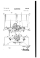
- Figure 1 is a top plan view of the device
- Figure 2 is a side elevational view of the infolding machine
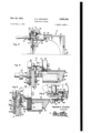
- Figure 3 is a vertical sectional view taken substantially on the plane 3--3 of Figure 1 showing the scoring roll engaging a strip;
- Figure 4 is a fragmentary vertical sectional view of the device taken substantially on the plane 4-4 of Figure 1 showing the edge of the strip being folded over after it is scored;
- Figure 5 is a fragmentary vertical sectional view of the device taken on the plane 5-5 of Figure 1 showing the infolded edge of the strip being pressed;
- Figure 6 is a fragmentary top detail view with the upper folding and pressing rollers removed.
- the platform l2 may conveniently be provided with legs l6 and a downwardly depending side wall I 8, which legs may be provided with laterally extending flanges 20 or the like by which the platform may be secured to a firm base.
- the infolding mechanism consists of a feed roll 22 which preferably is formed of resilient material, the feed roll having an axle 24, which axle is journaled at its inner end in the bearing 26, which bearing is secured to or formed as part of the undersurface of the platform I2.
- the outer end of the axle 24 being journaled in, and projecting through the side wall l8 as at 23.
- a slot 30 is provided in the platform l2 so as to permit the upper surface of the feed roll 22 to project slightly above the platform.
- a lower pressing roll 32 is also rotatably mounted on said platform, as by shaft 34.
- the shaft 34 is journaled, at its inner end in the bearing 36, not shown, the outer end being journaled in the side wall l8 as at 38 and projecting therethrough.
- a slot 40 similar to that prescribed for the feed roll 22 is also provided so that the pressing roll 32 may project slightly above the platform [2.
- the lower pressing roll may be knurled as at 42 so that the pressing roll will also aid in feeding a strip material 44, the knurls positively engaging the strip.
- a single longitudinal slot 46 in the platform l2 may be provided in order to simplify the molding process, the slot 46 providing a common aperture for purposes which will later become apparent.
- the slot 46 communicates the outer ends of the slots 30 and 40 and terminates adjacent the side wall I8.
- a substantially L-shaped rail 48 having a twisted portion 50 adjacent its rear end is secured to the platform l2 longitudinally of the slot 46, the portion 50 being formed by twisting the vertical le of the rail 48 one quarter turn clockwise.
- This rail 48 may be secured to the undersurface of the platform 12 adjacent the forward end of the slot 46 as by bolts 52 which are received in threaded bores in the platform.
- a plate 54 is provided which pl te h s it opposite edges adjacent the periphery of the feed roll 22 and the pressing roll 32.
- this plate may be provided with a laterally offset portion 55 which is welded or otherwise secured to the horizontal leg of the L-shaped rail 48, the other end resting on the platform I2 as at 56.
- an upper feed idler roll 58 is secured to or formed as part thereof.
- An arm 5% which is pivotally secured at one end as by bolt 62 to the side wall i8, is provided with a stub sha t 65 at its other end, which stub shaft rotatably receives the flanged idler roll 58, the arm Gil being so positioned as to support the idler roll 58 in vertical alignment with the feed roll 22.
- a pin 66 is secured to, and extends laterally of the arm G3, a Wire '68 being secured to the free end of the pin 56.
- An eye bolt 70, or the like is attached to the other end of the spring 98, the eye bolt lil extending through an aperture 1'2 in an anchor plate M, which plate is secured to the side wall i8. is provided for adjusting the tension of the Wire 68 and consequently varying the pressure exerted by the roll 58 on the roll 22.
- the other end of the arm [8 is provided with a stub shaft 82 on which is rotatably journaled an idler pressing roll 84.
- other end of the spring 88 is attached to an eye bolt 90 similar to the bolt ES, which bolt is secured to the plate i by a Wing nut 92.
- Forward and rear strip guides 5t and 96 respectively are attached to the platform l2 longitudinally thereof.
- Transverse slots 98 which receive the guide securing bolts Hit, are provided to permit lateral adjustment of the guides.
- the guides 94 and st preferably have a strip receiving recess I02 so that the strip will be laterally guided and at the same time be constrained from vertical movement relative to the guide.
- a common driving means is provided for the feed and pressing rolls, which means may conveniently comprise preferably identical gears I04 and IE6 which are respectively attached to the external projections of the axle 24 and the shaft 34.
- An idler gear M38 is rotatably secured to a stub shaft H0, so as to be constantly in mesh with the gears I54 and I56.
- a crank H2 is secured to one of the shafts. Obviously placement of the crank on the stub shaft Hi1 will cause the rolls to rotate reversely of the direction of rotation of the crank, attachment of the crank to the axle 24 or the shaft 34 causing rotation of the rolls in the same direction as the rotation of the crank.
- a strip of material 44 is placed in the forward guide 94 and fed to the feed roll 22.
- depresses the strip between the edge of the roll 22 and the rail 28, the rail 48 causing the edge of the strip to be bent substantially at right angles to the strip M.
- the twisted portion 56 completes the infolding of the edge and as can be seen from Figure 4, the presser roll 42 and the idler roll 84 press the infolded edge of the strip 44.
- the infolding device I0 will accommodate materials of varying grades and thickness in that the rolls are resiliently urged together to thereby automatically accommodate minor variations in the thickness.
- a folding machine comprising a support substantially vertically spaced, upper and lower feed rolls rotatably mounted on said support and having forward ends terminating in a common plane, one of said feed rolls having a bending flange on the forward end thereof intersecting the path of rotation of the other of said feed rolls, substantially vertically aligned upper and lower pressing rolls rotatably mounted on said support and spaced horizontally from said feed rolls, said pressing rolls bein longitudinally offset from said feed rolls, the bending flange being disposed intermediate the ends of the pressing rolls, infolding means attached to said support, said infolding means comprising an elongated rail mounted on said support in front of the forward ends of said feed rolls and extending adjacent and parallel to the bending flange, said rail terminating short of said pressing rolls and including a twisted portion between the feed and pressing rolls intersecting the plane of the bending flange, guide means on said support being laterally offset from said elongated rail, the elongated rail being disposed between the guide means and the bending flange and the feed
Landscapes
- Engineering & Computer Science (AREA)
- Mechanical Engineering (AREA)
- Casting Or Compression Moulding Of Plastics Or The Like (AREA)
Description
Feb. 24, 1953 R. E. ERICKSON 2,629,422
INSULATION CUFFER Filed May 11, 1950 2 SHEETS-SHEET 1 Fig.
Reynold E. Erickson Fig 2 INVENTOR.
Feb. 24, 1953 R. E. ERICKSON INSULATION CUF FER Filed May 11, 1950 2 SHEETS-SHEET 2 Reyna/d E. Erickson INVENTOR. @310. mm
an; E
Fly 4 Patented Feb. 24, 1953 UNITED STATES PATENT OFFICE INSULATION CUFFER n Reynold E. Erickson, Chico, Calif. Application May 11, 1950, Serial No. 161,365
This invention comprises novel and useful improvements in folding machines, and more particularly pertains to a device for infolding the edge of a strip.
An important object of this invention is to provide a strip infolding machine which can be used to infold strips of varying thickness and grades of material.
Another important object ofthis invention is to provide an infolding machine in accordance with the foregoing object in which the width of the infold can be readily varied.
Yet another object of this invention is to provide an infolding machine in accordance with the foregoing objects which is of simple construction yet durable and highly efficient for the purposes intended.
An important feature of this invention resides in the provision for upper and lower feed rolls and upper and lower pressing rolls which are laterally shiftable relative to each other, together with means yieldingly urging the upper and lower rolls of each set together.
An important featureof this invention resides in the provision for means for adjusting the pressure exerted by the means for urging the upper and lower rolls of each set together.
Another feature of this invention resides in the provision for an adjustable guide for a strip so that the width of infold on the strip can be varied.
These, together with various ancillary objects and features, are attained by this device, a preferred embodiment of which has been illustrated by Way of example only in the accompanying drawings wherein:
Figure 1 is a top plan view of the device;
Figure 2 is a side elevational view of the infolding machine;
Figure 3 is a vertical sectional view taken substantially on the plane 3--3 of Figure 1 showing the scoring roll engaging a strip;
Figure 4 is a fragmentary vertical sectional view of the device taken substantially on the plane 4-4 of Figure 1 showing the edge of the strip being folded over after it is scored;
Figure 5 is a fragmentary vertical sectional view of the device taken on the plane 5-5 of Figure 1 showing the infolded edge of the strip being pressed; and
Figure 6 is a fragmentary top detail view with the upper folding and pressing rollers removed.
Referring now more specifically to the accompanying drawings wherein like numerals designate similar parts throughout the various views,
6 Claims. (Cl. 153-28) it can be seen that the infolding machine, indicated generally by the numeral l0 consists of a platform I2 to which is attached an infolding mechanism l4.
The platform l2 may conveniently be provided with legs l6 and a downwardly depending side wall I 8, which legs may be provided with laterally extending flanges 20 or the like by which the platform may be secured to a firm base.
The infolding mechanism consists of a feed roll 22 which preferably is formed of resilient material, the feed roll having an axle 24, which axle is journaled at its inner end in the bearing 26, which bearing is secured to or formed as part of the undersurface of the platform I2. The outer end of the axle 24 being journaled in, and projecting through the side wall l8 as at 23. A slot 30 is provided in the platform l2 so as to permit the upper surface of the feed roll 22 to project slightly above the platform.
A lower pressing roll 32 is also rotatably mounted on said platform, as by shaft 34. The shaft 34 is journaled, at its inner end in the bearing 36, not shown, the outer end being journaled in the side wall l8 as at 38 and projecting therethrough. A slot 40, similar to that prescribed for the feed roll 22 is also provided so that the pressing roll 32 may project slightly above the platform [2. The lower pressing roll may be knurled as at 42 so that the pressing roll will also aid in feeding a strip material 44, the knurls positively engaging the strip.
If the platform I2 is to be of moulded or cast material, a single longitudinal slot 46 in the platform l2 may be provided in order to simplify the molding process, the slot 46 providing a common aperture for purposes which will later become apparent. As can be ascertained from a consideration of Figure 6, the slot 46 communicates the outer ends of the slots 30 and 40 and terminates adjacent the side wall I8.
A substantially L-shaped rail 48 having a twisted portion 50 adjacent its rear end is secured to the platform l2 longitudinally of the slot 46, the portion 50 being formed by twisting the vertical le of the rail 48 one quarter turn clockwise. This rail 48 may be secured to the undersurface of the platform 12 adjacent the forward end of the slot 46 as by bolts 52 which are received in threaded bores in the platform. In order to prevent the strip of material from underpassing the lower feed roll 32; a plate 54 is provided which pl te h s it opposite edges adjacent the periphery of the feed roll 22 and the pressing roll 32. For convenience in mounting, this plate may be provided with a laterally offset portion 55 which is welded or otherwise secured to the horizontal leg of the L-shaped rail 48, the other end resting on the platform I2 as at 56.
Adjustably mounted relative to the feed roll 22, is an upper feed idler roll 58, a bending flange 6! being secured to or formed as part thereof. An arm 5%, which is pivotally secured at one end as by bolt 62 to the side wall i8, is provided with a stub sha t 65 at its other end, which stub shaft rotatably receives the flanged idler roll 58, the arm Gil being so positioned as to support the idler roll 58 in vertical alignment with the feed roll 22. A pin 66 is secured to, and extends laterally of the arm G3, a Wire '68 being secured to the free end of the pin 56. An eye bolt 70, or the like is attached to the other end of the spring 98, the eye bolt lil extending through an aperture 1'2 in an anchor plate M, which plate is secured to the side wall i8. is provided for adjusting the tension of the Wire 68 and consequently varying the pressure exerted by the roll 58 on the roll 22.
An arm :8, similar to the arm 65, is also pivoted as by bolt 83 to the side wall H3. The other end of the arm [8 is provided with a stub shaft 82 on which is rotatably journaled an idler pressing roll 84. A pin, 85, having one end secured to the arm 78, the other end having a spring 88 attached thereto, is provided. other end of the spring 88 is attached to an eye bolt 90 similar to the bolt ES, which bolt is secured to the plate i by a Wing nut 92.
Forward and rear strip guides 5t and 96 respectively are attached to the platform l2 longitudinally thereof. Transverse slots 98, which receive the guide securing bolts Hit, are provided to permit lateral adjustment of the guides. The guides 94 and st preferably have a strip receiving recess I02 so that the strip will be laterally guided and at the same time be constrained from vertical movement relative to the guide.
A common driving means is provided for the feed and pressing rolls, which means may conveniently comprise preferably identical gears I04 and IE6 which are respectively attached to the external projections of the axle 24 and the shaft 34. An idler gear M38 is rotatably secured to a stub shaft H0, so as to be constantly in mesh with the gears I54 and I56. such as a crank H2 is secured to one of the shafts. Obviously placement of the crank on the stub shaft Hi1 will cause the rolls to rotate reversely of the direction of rotation of the crank, attachment of the crank to the axle 24 or the shaft 34 causing rotation of the rolls in the same direction as the rotation of the crank.
In operation a strip of material 44 is placed in the forward guide 94 and fed to the feed roll 22. As can be readily ascertained from Figure 3, the bending flange 6| depresses the strip between the edge of the roll 22 and the rail 28, the rail 48 causing the edge of the strip to be bent substantially at right angles to the strip M. The twisted portion 56 completes the infolding of the edge and as can be seen from Figure 4, the presser roll 42 and the idler roll 84 press the infolded edge of the strip 44.
Obviously the width of the infolded edge can be readily varied by adjustment of the guide 84.
It is also believed apparent that the infolding device I0 will accommodate materials of varying grades and thickness in that the rolls are resiliently urged together to thereby automatically accommodate minor variations in the thickness.
A thumb screw 76 The A driving means From the foregoing the construction and operation of the device will be readily understood, and further discussion is accordingly be-' lieved to be unnecessary. However, since numerous modifications will readily occur to those skilled in the art after a consideration of the foregoing specification and accompanying drawings, it is not desired to limit the invention to that shown and described, but all suitable modifications may be resorted to falling within the scope of the appended claims.
Having described the invention, claimed as new is:
1. A folding machine comprising a support substantially vertically spaced, upper and lower feed rolls rotatably mounted on said support and having forward ends terminating in a common plane, one of said feed rolls having a bending flange on the forward end thereof intersecting the path of rotation of the other of said feed rolls, substantially vertically aligned upper and lower pressing rolls rotatably mounted on said support and spaced horizontally from said feed rolls, said pressing rolls bein longitudinally offset from said feed rolls, the bending flange being disposed intermediate the ends of the pressing rolls, infolding means attached to said support, said infolding means comprising an elongated rail mounted on said support in front of the forward ends of said feed rolls and extending adjacent and parallel to the bending flange, said rail terminating short of said pressing rolls and including a twisted portion between the feed and pressing rolls intersecting the plane of the bending flange, guide means on said support being laterally offset from said elongated rail, the elongated rail being disposed between the guide means and the bending flange and the feed rolls being disposed between the guide means and the pressing rolls and driving means for said feed and pressing rolls.
2. The combination of claim 1 wherein said guide means is laterally adjustable relative to said support and said infolding means.
3. The combination of claim 1 wherein said bending flange is secured to said upper feed roll so as to lie between said lower feed roll and said rail-like portion and have its lower edge lie below the upper surfaces of said rail-like portion and said lower feed roll.
4. The combination of claim 1 wherein said upper feed roll and said upper pressing roll are pivotally attached to said support.
5. The combination of claim l including resilient means yieldingly urging said upper feed roll and said upper pressing roll into engagement with said lower feed roll and said lower pressing roll respectively.
6. The combination of claim 5 including means for adjusting said resilient means.
What is REYN OLD E. ERICKSON.
REFERENCES CITED The following references are of record in the file of this patent:
UNITED STATES PATENTS Germany Apr.- 22, 1931
Priority Applications (1)
| Application Number | Priority Date | Filing Date | Title |
|---|---|---|---|
| US161365A US2629422A (en) | 1950-05-11 | 1950-05-11 | Insulation cuffer |
Applications Claiming Priority (1)
| Application Number | Priority Date | Filing Date | Title |
|---|---|---|---|
| US161365A US2629422A (en) | 1950-05-11 | 1950-05-11 | Insulation cuffer |
Publications (1)
| Publication Number | Publication Date |
|---|---|
| US2629422A true US2629422A (en) | 1953-02-24 |
Family
ID=22580900
Family Applications (1)
| Application Number | Title | Priority Date | Filing Date |
|---|---|---|---|
| US161365A Expired - Lifetime US2629422A (en) | 1950-05-11 | 1950-05-11 | Insulation cuffer |
Country Status (1)
| Country | Link |
|---|---|
| US (1) | US2629422A (en) |
Cited By (1)
| Publication number | Priority date | Publication date | Assignee | Title |
|---|---|---|---|---|
| US4558581A (en) * | 1983-09-16 | 1985-12-17 | At&T Technologies, Inc. | Guiding an advancing strip |
Citations (3)
| Publication number | Priority date | Publication date | Assignee | Title |
|---|---|---|---|---|
| US790797A (en) * | 1904-01-16 | 1905-05-23 | James R Little | Creasing and folding machine. |
| DE523353C (en) * | 1927-12-10 | 1931-04-22 | Jaklin Hans | Process for the production of building supports folded in an I-shape from sheet metal or strip iron |
| US2194114A (en) * | 1937-12-02 | 1940-03-19 | Embree Herbert | Flanging machine |
-
1950
- 1950-05-11 US US161365A patent/US2629422A/en not_active Expired - Lifetime
Patent Citations (3)
| Publication number | Priority date | Publication date | Assignee | Title |
|---|---|---|---|---|
| US790797A (en) * | 1904-01-16 | 1905-05-23 | James R Little | Creasing and folding machine. |
| DE523353C (en) * | 1927-12-10 | 1931-04-22 | Jaklin Hans | Process for the production of building supports folded in an I-shape from sheet metal or strip iron |
| US2194114A (en) * | 1937-12-02 | 1940-03-19 | Embree Herbert | Flanging machine |
Cited By (1)
| Publication number | Priority date | Publication date | Assignee | Title |
|---|---|---|---|---|
| US4558581A (en) * | 1983-09-16 | 1985-12-17 | At&T Technologies, Inc. | Guiding an advancing strip |
Similar Documents
| Publication | Publication Date | Title |
|---|---|---|
| US2938723A (en) | Side guide register for sheet feeders | |
| US3567216A (en) | Automatic levelling device for a feeding unit on an offset printing machine or the like | |
| CN209981006U (en) | A bulk capacitor clipping device | |
| US2629422A (en) | Insulation cuffer | |
| US2132344A (en) | Bobbin stripper | |
| US2155895A (en) | Automatic feeding device | |
| US2216453A (en) | Stapling machine | |
| US2219892A (en) | Sheet feeding mechanism | |
| CN219927075U (en) | Compressing device of automatic carton binding machine | |
| US2449776A (en) | Unit strip assembly method and apparatus | |
| US2584855A (en) | Box blank folding machine | |
| US1805907A (en) | Veneer taping machine | |
| US2126138A (en) | Folding machine | |
| US2272323A (en) | Envelope opening machine | |
| US1686466A (en) | Bead-covering machine | |
| US1627667A (en) | Machine for making corner mounts | |
| US1126292A (en) | Veneer jointing and taping machine. | |
| US1110380A (en) | Moistening attachment for corner-staying machines. | |
| US2894355A (en) | Endless paper roll type drafting board | |
| US1932506A (en) | Feed regulator for stripping machines | |
| US2546172A (en) | L-type binding guide | |
| US1897484A (en) | Mechanism for feeding blanks | |
| US1302153A (en) | Cigar-bunch-making machine. | |
| US2047993A (en) | Machine for coating printers' rollers | |
| US1479898A (en) | Caramel-forming machine |