US2629291A - Machine tool - Google Patents
Machine tool Download PDFInfo
- Publication number
- US2629291A US2629291A US757256A US75725647A US2629291A US 2629291 A US2629291 A US 2629291A US 757256 A US757256 A US 757256A US 75725647 A US75725647 A US 75725647A US 2629291 A US2629291 A US 2629291A
- Authority
- US
- United States
- Prior art keywords
- gear
- shaft
- spindle
- tool
- sleeve
- Prior art date
- Legal status (The legal status is an assumption and is not a legal conclusion. Google has not performed a legal analysis and makes no representation as to the accuracy of the status listed.)
- Expired - Lifetime
Links
- 230000007246 mechanism Effects 0.000 description 23
- 230000001976 improved effect Effects 0.000 description 11
- 239000012530 fluid Substances 0.000 description 9
- 238000010276 construction Methods 0.000 description 6
- 238000005520 cutting process Methods 0.000 description 6
- 238000006073 displacement reaction Methods 0.000 description 6
- 230000006835 compression Effects 0.000 description 5
- 238000007906 compression Methods 0.000 description 5
- 238000003754 machining Methods 0.000 description 5
- 230000009471 action Effects 0.000 description 4
- 238000010586 diagram Methods 0.000 description 4
- 238000004891 communication Methods 0.000 description 3
- 230000000694 effects Effects 0.000 description 3
- 230000002441 reversible effect Effects 0.000 description 2
- 101150067539 AMBP gene Proteins 0.000 description 1
- 241000606643 Anaplasma centrale Species 0.000 description 1
- 240000002317 Camassia leichtlinii Species 0.000 description 1
- 235000000459 Camassia leichtlinii Nutrition 0.000 description 1
- 238000007599 discharging Methods 0.000 description 1
- 239000002783 friction material Substances 0.000 description 1
- 230000002452 interceptive effect Effects 0.000 description 1
- 230000001788 irregular Effects 0.000 description 1
- 230000003340 mental effect Effects 0.000 description 1
- 238000000034 method Methods 0.000 description 1
- 238000003801 milling Methods 0.000 description 1
- 230000004048 modification Effects 0.000 description 1
- 238000012986 modification Methods 0.000 description 1
- 230000009467 reduction Effects 0.000 description 1
- 239000011435 rock Substances 0.000 description 1
- 230000000153 supplemental effect Effects 0.000 description 1
- 230000003245 working effect Effects 0.000 description 1
Images


Classifications
-
- B—PERFORMING OPERATIONS; TRANSPORTING
- B23—MACHINE TOOLS; METAL-WORKING NOT OTHERWISE PROVIDED FOR
- B23F—MAKING GEARS OR TOOTHED RACKS
- B23F5/00—Making straight gear teeth involving moving a tool relatively to a workpiece with a rolling-off or an enveloping motion with respect to the gear teeth to be made
- B23F5/20—Making straight gear teeth involving moving a tool relatively to a workpiece with a rolling-off or an enveloping motion with respect to the gear teeth to be made by milling
- B23F5/205—Making straight gear teeth involving moving a tool relatively to a workpiece with a rolling-off or an enveloping motion with respect to the gear teeth to be made by milling with plural tools
-
- B—PERFORMING OPERATIONS; TRANSPORTING
- B23—MACHINE TOOLS; METAL-WORKING NOT OTHERWISE PROVIDED FOR
- B23F—MAKING GEARS OR TOOTHED RACKS
- B23F5/00—Making straight gear teeth involving moving a tool relatively to a workpiece with a rolling-off or an enveloping motion with respect to the gear teeth to be made
- B23F5/20—Making straight gear teeth involving moving a tool relatively to a workpiece with a rolling-off or an enveloping motion with respect to the gear teeth to be made by milling
- B23F5/22—Making straight gear teeth involving moving a tool relatively to a workpiece with a rolling-off or an enveloping motion with respect to the gear teeth to be made by milling the tool being a hob for making spur gears
-
- Y—GENERAL TAGGING OF NEW TECHNOLOGICAL DEVELOPMENTS; GENERAL TAGGING OF CROSS-SECTIONAL TECHNOLOGIES SPANNING OVER SEVERAL SECTIONS OF THE IPC; TECHNICAL SUBJECTS COVERED BY FORMER USPC CROSS-REFERENCE ART COLLECTIONS [XRACs] AND DIGESTS
- Y10—TECHNICAL SUBJECTS COVERED BY FORMER USPC
- Y10T—TECHNICAL SUBJECTS COVERED BY FORMER US CLASSIFICATION
- Y10T409/00—Gear cutting, milling, or planing
- Y10T409/10—Gear cutting
- Y10T409/101431—Gear tooth shape generating
- Y10T409/10159—Hobbing
- Y10T409/102226—Hobbing with control means energized in response to activator stimulated by condition sensor
-
- Y—GENERAL TAGGING OF NEW TECHNOLOGICAL DEVELOPMENTS; GENERAL TAGGING OF CROSS-SECTIONAL TECHNOLOGIES SPANNING OVER SEVERAL SECTIONS OF THE IPC; TECHNICAL SUBJECTS COVERED BY FORMER USPC CROSS-REFERENCE ART COLLECTIONS [XRACs] AND DIGESTS
- Y10—TECHNICAL SUBJECTS COVERED BY FORMER USPC
- Y10T—TECHNICAL SUBJECTS COVERED BY FORMER US CLASSIFICATION
- Y10T409/00—Gear cutting, milling, or planing
- Y10T409/10—Gear cutting
- Y10T409/101431—Gear tooth shape generating
- Y10T409/10159—Hobbing
- Y10T409/102385—Plural hobs
-
- Y—GENERAL TAGGING OF NEW TECHNOLOGICAL DEVELOPMENTS; GENERAL TAGGING OF CROSS-SECTIONAL TECHNOLOGIES SPANNING OVER SEVERAL SECTIONS OF THE IPC; TECHNICAL SUBJECTS COVERED BY FORMER USPC CROSS-REFERENCE ART COLLECTIONS [XRACs] AND DIGESTS
- Y10—TECHNICAL SUBJECTS COVERED BY FORMER USPC
- Y10T—TECHNICAL SUBJECTS COVERED BY FORMER US CLASSIFICATION
- Y10T409/00—Gear cutting, milling, or planing
- Y10T409/10—Gear cutting
- Y10T409/101431—Gear tooth shape generating
- Y10T409/10159—Hobbing
- Y10T409/102544—Hobbing including infeed means
- Y10T409/102703—Hobbing including infeed means to infeed along axis of work rotation
Definitions
- the present invention relates to machine tools and more particularly to rotary gear cutting or bobbing machines of the turret type.
- An object of the present invention is the provision or an improved hobbing machine of the turret type which operates in a more efficient and improved manner than prior art machines.
- Another object of the invention is the provision of an improved machine tool of the rotary turret type comprising a plurality of tool spindles each cooperating with a separate work support to form a plurality of operational units for effecting a hobbing or other machining operations, each unit being provided with improved electrical controls whereby each unit may be operated independently of the others or in timed relationship therewith.
- a further object of the invention is the provision of an improved machine tool, comprising relatively movable tool and work supports and means for producing rotation of the work support in timed relationship with the rotation of the tool, in which the means for effecting rotation of the work support acts on the opposite side of the axis of the work support from the Iposi-tion occupied b-y the tool, thereby producing a balanced drive of the work support.
- a still further object of the invention is to provide an impro-ved machine tool of the rotary turret type having a plurality of relatively movable tool spindles and work supports, in which the work supporting means comprise iiuid operated mechanism for Vpositioning and holding the work during a machining operation.
- Another object of the invention is to provide an improved machine tool of the rotary turret type, having a plurality of relatively movable tool and work spindles forming a plurality o-f operational uni-ts, with a common source o-f power for operating all of said spindles and with a clutch for each unit interposed between the common source of power and the spindles of each unit, each unit further comprising uid pressure actuated means for selectively operating the clutch of the unit.
- Still another object of the invention is to provide an improved machine tool of the type mentioned in the two next preceding objects and in which the fluid operated means for holding the work and operating the clutches are automatically actuated during the working cycle of the machine.
- An additional object of the invention is to provide an improved hobbingmachine with novel electrical controls whereby the machine can be readily adapted to operate in accordance With ⁇ either the conventional or climb methods of hobbing and With or without automatic clean up of the work following a hobbing operation.
- the invention further resides in certain novel features, Idetails of construction, and combinations and arrangements oi parts, and further objects and advantages thereof will be apparent to those skilledin the art to which the invention pertains from the following description of the present preferred embodiment and one modification thereof, described with reference to the accompanying drawings in which similar reference characters represent corresponding parts throughout the several views and in which:
- Fig. 1 is a perspective view of a rotatable turret type hobbing machine embodying the present preferred for-m of the invention, certain portions being broken away and others omitted for the purpose of clarity;
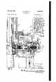
- Fig. 2 is a fragmentary view of the machine shown in Fig. 1, the view being partly in section and parftlyin elevation with the section being taken approximately on the centerline of the machine and with the illustrated tool or hob head turned to a horizontal position;
- Fig. 3 is an enlarged view of a portion of Fig. 2 with additional parts broken away to reveal the drive for the tool or hob and the drive for feeding and rotating the work support of one unit of the machine;
- Fig. 4 is a vertical sectional view through the lower portion of the work head illustrated in Fig. 2, the view being taken substantially on the lines 4-4 of Figs. 2 and 7;
- Fig. 5 is a side view, partly in section and partly in elevation, of the rapid traverse mechanism for a single unit of the machine, the view being taken substantially on the line 55 of Fig. 6;
- Fig. 6 is a top view of the rapid traverse mechanism illustrated in Fig. 5 with portions broken Iaway to more clearly reveal the construction;
- Fig. 7 is a sectional view through the lower portion of the work head, the view being taken substantially on the irregular section indicating 3 line 1-1 of Fig. 4, with certain parts broken -away to more clearly illustrate the gearing connections;
- Fig. 8 is a longitudinal sectional View through one of the tool or hob heads with certain members shown in elevation;
- Fig. 9 is a sectional view on the line 9 9 of Fig. 8;
- Fig. 10 is a fragmentary sectional View through one of the tailstock supporting means taken substantially on the line Illl of Fig. 1;
- Fig. 11 is a longitudinal sectional view through one of the improved uid operated tailstock mechanisms and a portion of the tailstock supporting means;
- Fig. 12 is a bottom elevational View of one of the tailstock mechanisms, only a portion of the tailstock supporting means illustrated in Fig. being shown;
- Fig. 13 is a fragmentary front elevational View of the top portion of one of the work heads of the machine illustrated in Fig. 1 showing certain of the switches operated by movement of the Work head;
- Fig. 14 is a fragmentary side view of the top portion of one of the work heads of the machine, the view being partly in elevation and partly in section and representing the righthand side of Fig. 13;
- Fig. 15 is a fragmentary side elevational View of a portion of the interior of the machine adjacent the top thereof illustrating the stationary cam for actuating a switch mounted on the back of each unit of the machine;
- Fig. 16 is a fragmentary View, partly in side elevation and partly in section, illustrating the air distributing means and one set of collector rings mounted at the top of the machine;
- Fig. 17 is a fragmentary front elevational View of one of the fluid pressure control means for controlling actuation'of the clutch illustrated in Figs. 2 and 3;
- Fig. 18 is a fragmentary top plan View of a portion of the housing for the collector rings illustrated in Figs. 2 and 3, the cover plate for the brushes being removed;
- Fig. 19 is a simplified wiring diagram of a portion of the electrical circuit for the machine illustrated in Figs. 1-17, the diagram being of the cross-the-line type employing the symbols conventionally utilized by the machine tool industry;
- Fig. 19A is a schematic representation of the same electric circuit as illustrated in Fig. 19 but drawn in a different style;
- Fig. 20 is a View similar to Fig. 3 but showing a modied form of clutch and clutch actuating means
- Fig. 21 is a simplified wiring diagram of a portion of the electrical circuit for a modined form of the machine of this invention utilizing the clutch and clutch actuating means illustrated in Fig. 20, the diagram being of the cross-the-line type employing the symbols conventionally uti- I lized by the machine tool industry;
- Fig. 21A is a schematic representation of the same electric circuit as illustrated in Fig. 21 but drawn in a different style.
- a rotatable turret type bobbing machine somewhat similar to that illustrated in U. S. Patent No. 2,292,260 and hence only those parts of the machine are here illustrated and described which The general nature of the machine is illustrated in Fig. 1 and may be briefly characterized as follows:
- the machine is supported by a stationary frame A on which a turret B is mounted for rotation in the direction indicated by the arrow R.
- a turret B At spaced points about the turret are mounted a plurality of identical tool or hob heads C and adjacent each tool head the turret carries a work head D, the latter being slidably supported for vertical movement relative to the corresponding tool head.
- Each tool head is provided with mechanism for supporting and rotating a hob or other tool, the tool being adapted to be rotated about an axis extending transversely of the vertical movement of the adjacent work head.
- each tool head C includes mechanism for producing a relatively slow axial movement of the hob or other tool while the latter is rotating.
- Each work head includes a means E for supporting and rotating a workpiece about a substantially vertical axis, and mechanism F for producing a feeding movement of the Work head vertically during a cutting operation. This rotation of the workpiece and the feeding movement thereof is in timed relationship to the rotation of the hob or other tool.
- the machine also includes a rapid traverse mechanism G for each work head to move the latter at a rapid rate to bring the work into cutting relationship with the hob or other tool and to return the work head to its initial position after the cutting operation has been completed.
- Each tool or hob head, work head, work gripping means and rapid traverse mechanism which are associated together form an operational or hobbing unit and are, at times, so referred to in the subsequent description and the subjoined claims.
- the turret thereof In operating the machine, the turret thereof is rotated so that the tool and work heads successively pass a definite position known ⁇ as the loading station where workpieces may be inserted and removed, the hobbing or other machining operation being effected as the turret continues to rotate and is completed by the time a given work head has returned to the loading station.
- the machine is capable of performing a hobbing or other machining operation either while the work heads are moving vertically upward or downward by virtue of operation of suitable electric switches, and the operation of any unit may be interrupted without interfering with the operation of the other units of the machine.
- the frame A comprises a bas-e 20 and a central, vertically extending column 2
- the turret B is rotatably supported upon the column and base by bearings 22, 23, and 24. Rotation of the turret B is effected by means o-f a motor 25 which operates through a suit-able reduction gearing 26 to rotate a worm .21
- a flange member 29 large diameter and may be integrafl with or attached to a flange member 29.
- the member 29 is secured by bolts, or other suitable means, to the lower part of a vertically extending annular member 30, which forms the main frame of the turret B.
- Each of the tool heads C comprises a tool or hob spindle 3
- Each spindle member 32 is adjustable, relative to its head member 33 about an axis normal to the axis of th-e hob spindle 3
- the head members 33 are slidably supported by horizontal ways 34 on the turret member 38 and the head members are adjustable therealong, radially of the axis about which the turret rotates, by means of screws 35 which engage a portion of the head members and are threaded into tapped holes in the turret member 30.
- Each of the work heads D is provided with a workho-lding and rotating means E which includes a Work spindle 36 (see Fig. 4) rotatably supported in the lower portion 31 of the work head by antifriction bearings 38, 39a and 39b.
- each spindle is provided with a chuck and each work head is further provided with a tail slide 40, slidably supported by ways 4
- the head members D are slidably supported yon vertical ways 44, provided on the turret member 30, and on vertical ways 45, provided on a cap member 46 which is integral with or secured to the top of the turret member 38 in any suitable manner.
- the work head members D are moved vertically along the Ways 44 and 45 by mechanism to be hereinafter described.
- and 36, respectively, are ro-tated in predetermined timed relationship by a motor 41, hereinafter referred to as the cut motor, which is supported upon an adjustable platform 48 on top of the column 2
- This motor is operatively connected to a shaft 49 through a flexible drive 58, the shaft 49 being connected by suitable gearing mechanism, contained Within the housing forming a part of the column 2
- a bevel gear 54 is attached to the lower end of the sleeve 52, by means of .bolts or the like, and the gear 54 meshes with a plurality of spaced bevel pinions 55, there being one bevel pinion 55 for each hobbing unit.
- Each pinion 55 is keyed to a, short shaft 56 (see Fig. 3) which is rotatably supported by bearings 51 and 58 in the rear portion of a two-part housing 59 attached to the member 30 and cap portion 46 of the turret B adjacent the edges of an opening therethrough.
- the drives for the various hobbing units from the gear 54 through the gears 55 are duplicates and, therefore, only one will be described in detail.
- the forward portion of the housing 59 extends int-o the hollow interior of the head member 33 and this portion of the housing is provided with an internal shoulder or flange 68 to the rear of which is connected a. collar member 6
- a shaft 62 is journalled in the collar member 6
- This clutch is of conventional design and compri-ses a driving u members 84, connected to the shaft 56, anda.
- driven member 65 which is connected to the shaft 62.
- the cooperating faces of the members 64 and 65 are provided with friction material 66 and 61, respectively, and are normally forced into engagement by a plurality of spaced compression coil springs 68 exerting force between the rear of the driven member 65 and a housing member 69 connected with the driving member.
- the rear face of the driven member 65 is provided with a plurality of integral bosses, only one of which is shown, in each of which is mounted an axially extending rod 18.
- Pivoted to each rod 10 is a radially extending actuating lever 1
- extend adjacent the shaft 62 and are adapted to be rocked in a counter-clockwise direction by an annular member 12 which is rotatably supported upon a sleeve 13 slidably supported upon the collar 6
- the sleeve 13 is straddled by the bifurcated lower end of an actuating member or lever 14, the forward faces of the bifurcated portion bearing against a cooperating surface on the sleeve 13.
- the lever 14 is pivoted intermediate its ends to bracket member 15 Which is mounted in an opening in the forward portion of the housing 59.
- lever 14 is pivotal'ly connected to a rod 16 which has an adjustable connection 11 with a piston rod 18.
- the piston rod. 18 extends into a cylinder 19 which is supported upon the cap member 46 of the turret by means of a plate having a depending bracket 8
- the inner end of the piston rod 18 is provided with a piston 82 which is adapted to be actuated to the right, as shown in Fig. 3, by fluid pressure a-dmitted to the rear end of the cylinder through a flexible pipe or hose 83, the forward portion of the cylinder being provided with an exhaust port, not shown, communicating the area in front of the piston with the atmosphere.
- a two-way valve 84 (see Figs. 1 and 17)'mounted upon the cap member 46 of the turret B.
- the pipe or hose 83 is connected to this valve 84 which is also provided with a fluid pressure supply pipe or hose 85 and an exhaust port 86, the latter having an adjustable orifice, such as a needle valve or the like, controlled by an adjusting screw 81.
- the movable member of the valve is connected by an actuating member or rod 88 to the armature of'an electrically operated solenoid 89, the valve being so formed that when the solenoid is energized communication is established between the fluid supply pipe or hose 85 and the pipe or hose 83 thus supplying uid pressure to the cylinder 19. Consequently, the piston 82 is forced to the right, as viewed in Fig. 3, rocking the lever 14 clockwise. This causes the sleeve 13 and annular member 12 to move axially to the left rocking the levers 1
- a bevel gear ill provided with an integral sleeve 92, is keyed to the shaft t2 intermediate the ends of the latter.
- the sleeve d2 is journalled by bearings 93 in the shoulder t of forward portion of the housing 59, the sleeve 92, and hence the gear 9
- the outer end of the'shaft t2 is splinedand provided with a bevel gear S which is slidably keyed to the shaft.
- rihe gear t5 is provided with an integral sleeve portion et which is rotatably supported in a member 9i by bearings at, the gear being held against longitudinal displacement relative to its bearings by a nut te threaded upon the sleeve portion Sie and the member 91 being attached to the spindle member 32.
- the outer face of the gear t5 is preferably provided with a cylindrical member which surrounds the outer end of shaft 52 to protect the latter.
- meshes with a bevel gear
- 62 forms a part of the work spindle rotating and feeding mechanism, which will be subsequently described in detail.
- the gear et is in mesh with another bevel gear iill mounted upon a shaft itil and forming a part of the drive for rotating and axially moving the tool or hob spindle 3
- the lower end of shaft it?. is splined and passes through a helical gear
- rlhe gear IGS is positioned within a housing
- 62 extends into a bore of the; housing
- 65 meshes with another helical gear i'l mounted upon a stub shaft
- the gear is also in mesh with a. helical gear I5 which is keyed to one end of a shaft Ht, the latter being rotatably supported by antifriction bearings
- the other end of the shaft carries a spur gear H9 for rotation therewith, and the gear H9 meshes with a Spui' gear
- is also provided with a spur gear
- 25 carries a worm
- 25 is provided with a pinion
- 33 also supports' a gear
- 35 meshes with a gear
- 42 comprises a cylindrical sleeve-like extension of the worm wheel
- rf'he sleevelike portion of the feed nut is journalled in a suitable bore-like opening within the portion 31 of the work head member by anti-friction bearings
- the bore in which the feed nut and screw are located may be closed by a suitable cap
- 02 is splined so that the gear
- the rotation of the work spindle 36 and the vertical movement thereof are in predetermined timed relationship and may be simultaneously started and stopped by the operation of the single clutch 63.
- This vertical movement of the work head and work spindle is that which is commonly known as a feeding movement and is eifected at a relatively slow rate while the hob or other tool supported upon the spindle 3
- Each work head D may be rapidly moved in a vertical direction by means of a separate rapid traverse mechanism G (see Figs. 5 and 6) which includes a motor
- cooperates with a worm wheel
- 48 is rotated, the feed screw
- 48 is preferably reversible and its shaft
- the vertical movement of the work heads is selectively effected at either the feed rate by motor 41, or at the rapid traverse rate by motors
- the spindle supporting member 32 is provided with an outboard bearing support
- 56 is provided with a non-rotatable sleeve
- 51 is provided with spaced antifriction bearings
- bothrotates and slides with the spindle'l 3
- 68 containing the mechanism for rotating and axially moving the tool or hob spindle 3
- This mechanism includes a gear
- This gear, and hence the spindle are driven by a gear
- 69 has a cylindrical sleeve-like extension
- 14 extend through the sleeve extension
- is a sleeve nut and sleeve nut, after the former has been screwed upon the latter, to prevent relative rotation between these parts when assembled.
- 18 which threada-bly engages the threads on the portion
- 18 extends beyond the end of the sleeve 11 and has an annular member
- 18 has a polygonally shaped axial opening
- Thisl stud extends beyond the sleeve nut
- 11 are rotatably supported by antifriction bearings
- the outer .surface of this .segmental plate is substantially coplanar With the outer surface of the .plate
- 9'3fis 'recesse'das by milling orlike operartion, .and tted therein is a langed'p'ortion
- 96 is disposed between one end 'of the arcuate opening
- a shaft ⁇ I 98 passes "through the arcuate 'openfi'n'g
- the gear 20e is inmesh Witha gear 205 Which ⁇ is one ofa pair of planetary gears-ro-v tatably supported upona short. shaft or bolt296, the latter being adjustably connected in a slot 1201 in the gear vsupporting plate I9I to permit i .Y properalignment'of the gears. Integral With,'or v"connected to, the 'gear 205" is'a smaller gear Vv2 08 v3 and 8).
- yRotation of the gear 222 causes the sleeve l
- 82, ⁇ the annular member is Jalsorotated With consequentrotation ofthe sleeve nut
- 15 is provided to'take up -any play between the sleevenut
- 15 remains stationary during'this ad- ⁇ justmexit since it is connected with the sleeve
- the several gears in the planetary system may have any desired ratios but are ⁇ preferably so chosen that the axial feed of the hob spindle is relatively slow.
- the rate is such as to produce complete axial movement during an interval of one work shift such as eight hours or the like.
- the hob or similar tool is so operated that the wear thereupon is substantially uniformly distributed over the entire surface of the hob.
- the hob spindle and hob are returned to their initial positions by rst rotating the handle 20
- a housing 223 for the electrical switch mechanisms Extending outwardly from the bearing support
- the switch 224 employed for this purpose is of the type known as a "microswitch having a double set of contacts, however, two separate microswitches each having a single set of contacts may be employed.
- the switch 224- is provided This, however, does not inter- *14 with an operating bar 225 extending substantially parallel with the outer surface of the bearing support
- is provided with a transverse bore in which is disposed a two-piece pin 228, the two portions of which are separated by a compression spring 229. This spring urges the two portions of the pin outwardly of the bore in the spindle so as to extend through an axial slot 230 provided in the sleeve
- the outer ends of this pin are positioned within a circular groove or recess on the inner face of a switch operating ring 23
- the construction is such that, when the spindle 9
- engages the actuating pin 22S, causing the latter to move outwardly thereby moving the operating bar 225.
- Each of the work heads D of the machine is provided with a fluid operated work holding means E for securing a work-piece to the work spindle.
- this means comprises an internal chuck 232 secured to the ⁇ upper end of spindle 36 for rotation therewith.
- the body of this chuck and the spindle 3a are provided with aligned bores through which a chuck actuating rod 233 extends, the upper end of the rod being provided with an enlarged portion having a substantially conical surface 234 slidable within a counterbore provided at the upper end of the chuck.
- Extending radially outwarcl through the side walls of the upper portion of the chuck are a plurality of work gripping fingers 235, the ngers being slidable radially and having inclined camming surfaces on their inner ends for cooperation with the conical surface 23d.
- the construction is such that, when the rod 233 is moved downwardly within the chuck 232, the fingers 235 are forced radially outwardly to engage the workpiece W and securely hold the latter.
- Movement of the rod 233 is effected, in accordance with this invention, by a uid operated means which comprises a cylinder 233 attached to the lower portion 31 of the work head D vby a suitable plate or bracket 231.
- the lower end of the rod 233 extends within the cylinder 239 and is provided therein with a piston, not shown which is adapted to be moved vertically in either direction by fluid under pressure supplied through pipes or hoses 238 and 239, which are connected to a source of fiuid under pressure in a manner hereinafter described.
Landscapes
- Engineering & Computer Science (AREA)
- Mechanical Engineering (AREA)
- Gear Processing (AREA)
Description
Feb. 24, 1953 O. E. STAPLES MACHINE TOOL Filed June 26, 1947 13 Sheets-Sheet l H rra/PNE Ys Feb. 24, 1953 Filed June 26. 194'? O. E. STAPLES MACHINE TOOL 15 Sheets-Sheet 2 20 26 BY icl-6.2
35@ 29 y r. ZW
Nb l l 35:; .75 aff 45 296 "is: 312 r 5%5 377 46 Br) 376 575 305 40 0 o 240 42 U5 3 79 l NJ |T= L Cm V 321 "d, "4I
l: m Inl 2 i r-J `4 ifV P y I /37 444 i I l w 24 l zza 2.9 G 2f INVENToR.
077.6* .STAPLES ,4r ron/vaya O. E. STAPLES MACHINE TOOL l5 Sheets-Sheet 3 Filed June 26, 1947 5 m 4 d M 1 ,.lGo /M 3 ON 9 huur lao ao www am 2 11| s M6 /f mw 3 i om my wd i www ,M/ 9 JW 7 H 0 qu w M 5 0 m 3 l 2 M5 l Il :j 5 3 a WH l I INVENTOR. 07-/5 E. STAPLs BY WWWW/w HFTae/vsys 13 Sheets-Sheet 4 Feb. 24, 1953 o. E. STAPLES MACHINE TOOL Filed June 26, 1947 O. E. STAPLES Feb. 24, 1953 MACHINE TOOL l5 Sheets-SheetA 5 Filed June 26, 1947 INVENTOR. 077s E. 524/1453 BY W, www im Hr ran/vaya Feb. 24, 1953 o. E. STAPLES 2,629,291
MACHINE Toor.
Filed June 2e, 1947 15 sheets-sheet e INVENTOR. r/s E. 5774/155 wam rromvsys Feb. 24,V 1953 o. E. STAPLES 2,629,291
,MACHINE Toor.
Filed June 26, 1947 15 Sheets-Sheet '7 765 172 g Il 170 '/9/ 205 j 1 .e
1&9 2W ,ZW 160 I 201 u iig 31 167 7a3? 177 156 2 7 zag- 174 77? 1 www z i 167 1 765 161 1% y 173 52 Feb. 24, 1953 o. E. STAPLES 2,629,291
MACHINE TOOL Filed June 26, 1947 15 Sheets-Sheet 8 fie. 77
INVENTOR. Or/s E. tvwuss O. E. STAPLES Feb. 24, 1953 MACHINE TOOL Filed .Jane 2e, 1947 13 Sheets-Sheet 9 M7 W71 Zw@ A Trae/vaya 56.20 www o. E. STAPLES 2,629,291
MACHINE TooL 13 Sheets-Sheet 10 Feb. 24, 1953 Filed June 26, 1947 mbv In EN v 5M me@ NNI .It mi NWS s.
57 Hrrae/vfys IN VEN T 0R.` 077.5 I .Samus Feb. 24, 1953 Filed June 26, 1947 O. E. STAPLES MACHINE TOOL Sheets-Sheet ll INVENTOR.
www, qm
Arme/Veys 0175 E. .S7-Pas O. E. STAPLES MACHINE TOOL Feb. 24, 1953 INVE/yToR.
Filed June 26, 1947 MQW Mahn {UMHIWI Fs www l B usw.
4 rma/ve ys Patented Feb. 24, 1953 MACHINE TOOL Otis E. Staples, Euclid, Ohio, assignor to The Cleveland Hobbing Machine Company, Euclid, Ohio, a corporation of Ohio Application June 26, 1947, Serial N0. 757,256
51 Claims.
The present invention relates to machine tools and more particularly to rotary gear cutting or bobbing machines of the turret type.
An object of the present invention is the provision or an improved hobbing machine of the turret type which operates in a more efficient and improved manner than prior art machines.
Another object of the invention is the provision of an improved machine tool of the rotary turret type comprising a plurality of tool spindles each cooperating with a separate work support to form a plurality of operational units for effecting a hobbing or other machining operations, each unit being provided with improved electrical controls whereby each unit may be operated independently of the others or in timed relationship therewith.
A further object of the invention is the provision of an improved machine tool, comprising relatively movable tool and work supports and means for producing rotation of the work support in timed relationship with the rotation of the tool, in which the means for effecting rotation of the work support acts on the opposite side of the axis of the work support from the Iposi-tion occupied b-y the tool, thereby producing a balanced drive of the work support.
A still further object of the invention is to provide an impro-ved machine tool of the rotary turret type having a plurality of relatively movable tool spindles and work supports, in which the work supporting means comprise iiuid operated mechanism for Vpositioning and holding the work during a machining operation.
Another object of the invention is to provide an improved machine tool of the rotary turret type, having a plurality of relatively movable tool and work spindles forming a plurality o-f operational uni-ts, with a common source o-f power for operating all of said spindles and with a clutch for each unit interposed between the common source of power and the spindles of each unit, each unit further comprising uid pressure actuated means for selectively operating the clutch of the unit.
Still another object of the invention is to provide an improved machine tool of the type mentioned in the two next preceding objects and in which the fluid operated means for holding the work and operating the clutches are automatically actuated during the working cycle of the machine.
It is also an object of the invention to provide an improved hobbing machine of the rotary turret type. having a plurality of hobs and cooperating work supports which are movable transversely of the axes of the hobs, with means for continuously moving of the hobs axially a small amount during the hobbing operation, the last-mentioned means further comprising mechanism to terminate operation of a hob and its associated work suppor-t when the hob has reached one extreme position thereof.
An additional object of the invention is to provide an improved hobbingmachine with novel electrical controls whereby the machine can be readily adapted to operate in accordance With `either the conventional or climb methods of hobbing and With or without automatic clean up of the work following a hobbing operation. The invention further resides in certain novel features, Idetails of construction, and combinations and arrangements oi parts, and further objects and advantages thereof will be apparent to those skilledin the art to which the invention pertains from the following description of the present preferred embodiment and one modification thereof, described with reference to the accompanying drawings in which similar reference characters represent corresponding parts throughout the several views and in which:
Fig. 1 is a perspective view of a rotatable turret type hobbing machine embodying the present preferred for-m of the invention, certain portions being broken away and others omitted for the purpose of clarity;
Fig. 2 is a fragmentary view of the machine shown in Fig. 1, the view being partly in section and parftlyin elevation with the section being taken approximately on the centerline of the machine and with the illustrated tool or hob head turned to a horizontal position;
Fig. 3 is an enlarged view of a portion of Fig. 2 with additional parts broken away to reveal the drive for the tool or hob and the drive for feeding and rotating the work support of one unit of the machine;
Fig. 4 is a vertical sectional view through the lower portion of the work head illustrated in Fig. 2, the view being taken substantially on the lines 4-4 of Figs. 2 and 7;
Fig. 5 is a side view, partly in section and partly in elevation, of the rapid traverse mechanism for a single unit of the machine, the view being taken substantially on the line 55 of Fig. 6;
Fig. 6 is a top view of the rapid traverse mechanism illustrated in Fig. 5 with portions broken Iaway to more clearly reveal the construction;
Fig. 7 is a sectional view through the lower portion of the work head, the view being taken substantially on the irregular section indicating 3 line 1-1 of Fig. 4, with certain parts broken -away to more clearly illustrate the gearing connections;
Fig. 8 is a longitudinal sectional View through one of the tool or hob heads with certain members shown in elevation;
Fig. 9 is a sectional view on the line 9 9 of Fig. 8;
Fig. 10 is a fragmentary sectional View through one of the tailstock supporting means taken substantially on the line Illl of Fig. 1;
Fig. 11 is a longitudinal sectional view through one of the improved uid operated tailstock mechanisms and a portion of the tailstock supporting means;
Fig. 12 is a bottom elevational View of one of the tailstock mechanisms, only a portion of the tailstock supporting means illustrated in Fig. being shown;
Fig. 13 is a fragmentary front elevational View of the top portion of one of the work heads of the machine illustrated in Fig. 1 showing certain of the switches operated by movement of the Work head;
Fig. 14 is a fragmentary side view of the top portion of one of the work heads of the machine, the view being partly in elevation and partly in section and representing the righthand side of Fig. 13;
Fig. 15 is a fragmentary side elevational View of a portion of the interior of the machine adjacent the top thereof illustrating the stationary cam for actuating a switch mounted on the back of each unit of the machine;
Fig. 16 is a fragmentary View, partly in side elevation and partly in section, illustrating the air distributing means and one set of collector rings mounted at the top of the machine;
Fig. 17 is a fragmentary front elevational View of one of the fluid pressure control means for controlling actuation'of the clutch illustrated in Figs. 2 and 3;
Fig. 18 is a fragmentary top plan View of a portion of the housing for the collector rings illustrated in Figs. 2 and 3, the cover plate for the brushes being removed;
Fig. 19 is a simplified wiring diagram of a portion of the electrical circuit for the machine illustrated in Figs. 1-17, the diagram being of the cross-the-line type employing the symbols conventionally utilized by the machine tool industry;
Fig. 19A is a schematic representation of the same electric circuit as illustrated in Fig. 19 but drawn in a different style;
Fig. 20 is a View similar to Fig. 3 but showing a modied form of clutch and clutch actuating means;
Fig. 21 is a simplified wiring diagram of a portion of the electrical circuit for a modined form of the machine of this invention utilizing the clutch and clutch actuating means illustrated in Fig. 20, the diagram being of the cross-the-line type employing the symbols conventionally uti- I lized by the machine tool industry;
Fig. 21A is a schematic representation of the same electric circuit as illustrated in Fig. 21 but drawn in a different style.
The invention is illustrated as embodied in a rotatable turret type bobbing machine somewhat similar to that illustrated in U. S. Patent No. 2,292,260 and hence only those parts of the machine are here illustrated and described which The general nature of the machine is illustrated in Fig. 1 and may be briefly characterized as follows:
The machine is supported by a stationary frame A on which a turret B is mounted for rotation in the direction indicated by the arrow R. At spaced points about the turret are mounted a plurality of identical tool or hob heads C and adjacent each tool head the turret carries a work head D, the latter being slidably supported for vertical movement relative to the corresponding tool head. Each tool head is provided with mechanism for supporting and rotating a hob or other tool, the tool being adapted to be rotated about an axis extending transversely of the vertical movement of the adjacent work head. In addition, each tool head C includes mechanism for producing a relatively slow axial movement of the hob or other tool while the latter is rotating. Each work head includes a means E for supporting and rotating a workpiece about a substantially vertical axis, and mechanism F for producing a feeding movement of the Work head vertically during a cutting operation. This rotation of the workpiece and the feeding movement thereof is in timed relationship to the rotation of the hob or other tool. The machine also includes a rapid traverse mechanism G for each work head to move the latter at a rapid rate to bring the work into cutting relationship with the hob or other tool and to return the work head to its initial position after the cutting operation has been completed. Each tool or hob head, work head, work gripping means and rapid traverse mechanism which are associated together form an operational or hobbing unit and are, at times, so referred to in the subsequent description and the subjoined claims.
In operating the machine, the turret thereof is rotated so that the tool and work heads successively pass a definite position known` as the loading station where workpieces may be inserted and removed, the hobbing or other machining operation being effected as the turret continues to rotate and is completed by the time a given work head has returned to the loading station. As will hereinafter appear, the machine is capable of performing a hobbing or other machining operation either while the work heads are moving vertically upward or downward by virtue of operation of suitable electric switches, and the operation of any unit may be interrupted without interfering with the operation of the other units of the machine. The manner in which each of the above mentioned operations is effected, and other features of the machine will hereinafter become apparent from the following detailed description.
Referring now to Figs. 1 and 2, it will be seen that the frame A comprises a bas-e 20 and a central, vertically extending column 2| uniting with the base and forming the main support for the machine. The turret B is rotatably supported upon the column and base by bearings 22, 23, and 24. Rotation of the turret B is effected by means o-f a motor 25 which operates through a suit-able reduction gearing 26 to rotate a worm .21
, and thereby drive the worm wheel 28, which is of are necessary to convey ya complete understand- Y ing of the invention to those skilled in the art.
large diameter and may be integrafl with or attached to a flange member 29. The member 29 is secured by bolts, or other suitable means, to the lower part of a vertically extending annular member 30, which forms the main frame of the turret B.
i conventional clamping plates and bolts.
of a friction plate clutch 83.
v Each of the tool heads C comprises a tool or hob spindle 3| rotatably supported upon a spindle member 32, which is in turn carried by a slidable head member 33 (see also Fig. 3). Each spindle member 32 is adjustable, relative to its head member 33 about an axis normal to the axis of th-e hob spindle 3| and is secured to the head member 33 in any adjusted position by bolts 32a, the hea-ds olf which engage within circular T- shaped openings 32b in the front face of the mem-ber 33. The head members 33 are slidably supported by horizontal ways 34 on the turret member 38 and the head members are adjustable therealong, radially of the axis about which the turret rotates, by means of screws 35 which engage a portion of the head members and are threaded into tapped holes in the turret member 30.
Each of the work heads D is provided with a workho-lding and rotating means E which includes a Work spindle 36 (see Fig. 4) rotatably supported in the lower portion 31 of the work head by antifriction bearings 38, 39a and 39b. The upper end of each spindle is provided with a chuck and each work head is further provided with a tail slide 40, slidably supported by ways 4| on the vertical portion 42 of the work head D, the several slides 48 each being held in any adjusted .position on the ways by suitable clamping means 43 which are illustrated as comprising The head members D are slidably supported yon vertical ways 44, provided on the turret member 30, and on vertical ways 45, provided on a cap member 46 which is integral with or secured to the top of the turret member 38 in any suitable manner. The work head members D are moved vertically along the Ways 44 and 45 by mechanism to be hereinafter described.
The tool and work spindles 3| and 36, respectively, are ro-tated in predetermined timed relationship by a motor 41, hereinafter referred to as the cut motor, which is supported upon an adjustable platform 48 on top of the column 2|. This motor is operatively connected to a shaft 49 through a flexible drive 58, the shaft 49 being connected by suitable gearing mechanism, contained Within the housing forming a part of the column 2|, to a sleeve 52 which is rotatably supported by bearings 53 on the vertical column 2|. A bevel gear 54 is attached to the lower end of the sleeve 52, by means of .bolts or the like, and the gear 54 meshes with a plurality of spaced bevel pinions 55, there being one bevel pinion 55 for each hobbing unit. Each pinion 55 is keyed to a, short shaft 56 (see Fig. 3) which is rotatably supported by bearings 51 and 58 in the rear portion of a two-part housing 59 attached to the member 30 and cap portion 46 of the turret B adjacent the edges of an opening therethrough. The drives for the various hobbing units from the gear 54 through the gears 55 are duplicates and, therefore, only one will be described in detail.
As shown in Fig. 3, the forward portion of the housing 59 extends int-o the hollow interior of the head member 33 and this portion of the housing is provided with an internal shoulder or flange 68 to the rear of which is connected a. collar member 6|. A shaft 62 is journalled in the collar member 6| and extends forwardly and rearwardly therebeyond, this shaft being selectively, operatively connected with the shaft 56 by means This clutch is of conventional design and compri-ses a driving u members 84, connected to the shaft 56, anda.
driven member 65 which is connected to the shaft 62. The cooperating faces of the members 64 and 65 are provided with friction material 66 and 61, respectively, and are normally forced into engagement by a plurality of spaced compression coil springs 68 exerting force between the rear of the driven member 65 and a housing member 69 connected with the driving member.
The rear face of the driven member 65 is provided with a plurality of integral bosses, only one of which is shown, in each of which is mounted an axially extending rod 18. Pivoted to each rod 10 is a radially extending actuating lever 1| which is urged to the illustrated position by the springs 68 since the lower portion of each lever engages a cam surface in a recess provided in. each of the integral bosses on the rear of the driven member. This action may be assisted, if desired, by providing each lever 1| with a supplemental spring, not shown. The upper portions of the levers 1| extend adjacent the shaft 62 and are adapted to be rocked in a counter-clockwise direction by an annular member 12 which is rotatably supported upon a sleeve 13 slidably supported upon the collar 6|. The sleeve 13 is straddled by the bifurcated lower end of an actuating member or lever 14, the forward faces of the bifurcated portion bearing against a cooperating surface on the sleeve 13. The lever 14 is pivoted intermediate its ends to bracket member 15 Which is mounted in an opening in the forward portion of the housing 59.
The upper end of lever 14 is pivotal'ly connected to a rod 16 which has an adjustable connection 11 with a piston rod 18. The piston rod. 18 extends into a cylinder 19 which is supported upon the cap member 46 of the turret by means of a plate having a depending bracket 8|l. The inner end of the piston rod 18 is provided with a piston 82 which is adapted to be actuated to the right, as shown in Fig. 3, by fluid pressure a-dmitted to the rear end of the cylinder through a flexible pipe or hose 83, the forward portion of the cylinder being provided with an exhaust port, not shown, communicating the area in front of the piston with the atmosphere.
The flow of fluid under pressure to the cylinder 19 is controlled by a two-way valve 84 (see Figs. 1 and 17)'mounted upon the cap member 46 of the turret B. As shown in Fig. 17, the pipe or hose 83 is connected to this valve 84 which is also provided with a fluid pressure supply pipe or hose 85 and an exhaust port 86, the latter having an adjustable orifice, such as a needle valve or the like, controlled by an adjusting screw 81. The movable member of the valve is connected by an actuating member or rod 88 to the armature of'an electrically operated solenoid 89, the valve being so formed that when the solenoid is energized communication is established between the fluid supply pipe or hose 85 and the pipe or hose 83 thus supplying uid pressure to the cylinder 19. Consequently, the piston 82 is forced to the right, as viewed in Fig. 3, rocking the lever 14 clockwise. This causes the sleeve 13 and annular member 12 to move axially to the left rocking the levers 1|, and the lower ends of the latter force the driven member 65 to the right, against the action of the springs 68, disengaging the clutch.
When the solenoid 89 is deenergized the movable member of the valve 84 is actuated to interrupt the communication between pipes or hoses 85 and 83 and to establish communication between the pipe or hose 83 and the exhaust port 86. Hence the springs 68 of the clutch act through the kdriven member |55, levers 1|, annuilar member 12 and sleeve 13 to rock the lever 14 in a counter-clockwise direction, this action being assisted by a compression spring Q mounted upon the bracket 15 and bearing against the lever 14 above its pivot. The counter-clockwise movement of the lever 1e moves the piston 32 to the left, as viewed in Fig. 3, thus discharging the fluid in the cylinder 'i9 through the pipe or hose B3, valve 84 and the exhaust port t6. The adjustable orifice in the port 8S controls the rate of discharge of the iiuid and hence the rate of engagement of the driven member 65 of the clutch with the driving member et, under the action of the springs 68, thus preventing grabbing. The manner in which the solenoid '59 is energized and deenergized during the working cycle of the machine to effect operation of the clutch |33 will be hereinafter described.
A bevel gear ill, provided with an integral sleeve 92, is keyed to the shaft t2 intermediate the ends of the latter. The sleeve d2 is journalled by bearings 93 in the shoulder t of forward portion of the housing 59, the sleeve 92, and hence the gear 9|, being held against axial displacement by a nut eli threaded upon a reduced end of the sleeve and engaging the adjacent end of the inner race for the bearings 93.
The outer end of the'shaft t2 is splinedand provided with a bevel gear S which is slidably keyed to the shaft. rihe gear t5 is provided with an integral sleeve portion et which is rotatably supported in a member 9i by bearings at, the gear being held against longitudinal displacement relative to its bearings by a nut te threaded upon the sleeve portion Sie and the member 91 being attached to the spindle member 32. The outer face of the gear t5 is preferably provided with a cylindrical member which surrounds the outer end of shaft 52 to protect the latter.
The bevel gear 9| meshes with a bevel gear ||Jl connected with the upper end of a vertical shaft |92, the latter being journalled by bearings ||l3 in an opening in the lower side of the forward portion of the housing 5t. This shaft |62 forms a part of the work spindle rotating and feeding mechanism, which will be subsequently described in detail. The gear et is in mesh with another bevel gear iill mounted upon a shaft itil and forming a part of the drive for rotating and axially moving the tool or hob spindle 3|. It will be apparent therefore, that when the clutch '63 is engaged, the shaft S2 will be rotated by the cut motor 4'! through the gears 54, 55, shaft 5t, and clutch t3 thus driving the shaft |02 for rotating and feeding the work spindle, as hereinafter described, the shaft it also being rotated for rotating and axially moving the tool spindle. Conversely, disengagement of the clutch 63 interrupts rotationv of the shaft 62 simultaneously stopping the mechanisms driven thereby.
As shown in Fig. fl, the lower end of shaft it?. is splined and passes through a helical gear |G| which is keyed to the splined portion of the shaft ||l2 t0 be rotated thereby, the splining permitting the gear to be slid axially along the shaft. rlhe gear IGS is positioned within a housing |91, attached to the lower portion 31 of the work head D, the gear being prevented from axial displacement relative to the housing by means of a nut and washer assembly itt which engages one side of the inner race for the antifriction bearings |09 in which the shaft N2 is journalled, the other side of the inner race of these bearings `being in engagementwth a shoulder formed by a sleeve-like portion of the gear |06; The lower end of the shaft |62 extends into a bore of the; housing ||i1 and is journalled by antifriction bearings v||l'|, which are positioned between a cylindrical sleeve extension of the gear |06 and the enlarged upper end of the aforementioned bore in the housing |01.
The helical gear |65 meshes with another helical gear i'l mounted upon a stub shaft ||2, the latter being journalled in a portion of the housing |91 by means of antifriction bearings H3, ||4 (see Fig. 7). -The gear is also in mesh with a. helical gear I5 which is keyed to one end of a shaft Ht, the latter being rotatably supported by antifriction bearings ||1, IIB in the housing |01 and in the portion 31 of the work head, respectively. The other end of the shaft carries a spur gear H9 for rotation therewith, and the gear H9 meshes with a Spui' gear |29 rotatably mounted upon a stub shaft |2|, the latter being supported by a bracket |22 connected with the portion 31 of the work head. The shaft |2| is also provided with a spur gear |23, connected to rotate with the spur gear |20, and the gear |23 meshes with a spur gear |24 keyed to onev end of a worm shaft |25, the latter being journalled by suitable antifriction bearings |25 and |2'| in a sleeve-like support |28 mounted in the portion 31 of the work head D. Intermediate its ends, and within the interior of the portion 31 of the work head, the shaft |25 carries a worm |29 which meshes with a worm wheel |39 secured to the work spindle 36. Therefore, when the clutch G3 is engaged, the motor 41 will effect rotation of shaft |02 thereby rotating the work spindle 36 through the gears |06, I||, ||5, H9, |23, |23, Hill, worm |29 and worm wheel |33.
The end of the worm shaft |25, opposite to the end on which is attached the gear |24, is provided with a pinion |3| which meshes with a gear |32 rotatably mounted upon a stub shaft |33, the latter being supported by a bracket 34 connected to portion 31 of the work head. The shaft |33 also supports' a gear |35 which is mounted to rotate `with the gear |32. The gear |35 meshes with a gear |35 which is keyed to' a shaft |31, this shaft being journalled by antifrictionbearings |38 and |39 in the portion 31 of the work head D. The inner end of the shaft |31 is pro,- vided with a worm Mil, which drives a worm wheel ifii forming a part of a feed nut |42. As shown in Fig. Ll, the feed nut |42 comprises a cylindrical sleeve-like extension of the worm wheel |4| and is internally threaded to cooperate with the threads on a feed screw or shaft |43. rf'he sleevelike portion of the feed nut is journalled in a suitable bore-like opening within the portion 31 of the work head member by anti-friction bearings |44 and |45, the nut being held against axial displacement relative to its bearings by means of a nut |46 in a well known manner. The bore in which the feed nut and screw are located may be closed by a suitable cap |41 to prevent the entrance of dirt, chips or the like.
Y The construction is such that when the clutch e3 is engaged, the motor 41 will drive the shaft |92 thereby rotating the worm shaft |25, in the manner previously described, and this rotation of the shaft |25 operates through the gears |3| |32, |35, |3t, worm |40, and worm wheel IM: forming a part of the feed nut |42. to cause the latter to rotate relative to the feed screw or shaft |43. Since the feed nut |42 is supported against axial movement, this rotation causes the said nut,
Vand hence the entire work head, to move vertically as the nut threads along the screw or shaft l end of the spindle 3|.
|43. As previously mentioned, the lower end of the shaft |02 is splined so that the gear |06 may move therealong during this operation. Moreover, the rotation of the work spindle 36 and the vertical movement thereof, are in predetermined timed relationship and may be simultaneously started and stopped by the operation of the single clutch 63. This vertical movement of the work head and work spindle is that which is commonly known as a feeding movement and is eifected at a relatively slow rate while the hob or other tool supported upon the spindle 3| performs a cutting or hobbing operation upon the work carried by the work spindle 36.
Each work head D may be rapidly moved in a vertical direction by means of a separate rapid traverse mechanism G (see Figs. 5 and 6) which includes a motor |48, the shaft |49 of which is connected to a worm shaft |50 upon which is mounted a worm |5|. The worm |5| cooperates with a worm wheel |52 connected for rotation with the lower end of the feed screw or shaft |43, the lower end of the latter being supported by suitable antifriction bearings |53 and |54 in the housing for the rapid traverse mechanism G. Hence, when the motor |48 is rotated, the feed screw |43 is rotated relative to the feed nut |42, thereby causing vertical movement of the Work head D ata relatively rapid rate, hereinafter referred to as rapid traverse. The motor |48 is preferably reversible and its shaft |49, or the worm shaft |50 connected thereto, is provided with an electrically operated brake |55 which is spring actuated to normally engage the shaft for preventing rotation of the latter and of the feed screw |43, the brake being provided with an electromagnet which releases the brake when energized. It will be observed that there is a separate rapid traverse motor |48 for each of the work heads carried by the machine so that the rapid traverse movement of each work head is independent of that of all the others. The vertical movement of the work heads is selectively effected at either the feed rate by motor 41, or at the rapid traverse rate by motors |48, as determined by actuation of switches in an `electrical circuit hereinafter described.
Referring now to Fig. 8, it will be seen that the spindle supporting member 32 is provided with an outboard bearing support |56 and an inboard bearing support |51, the latter preferably being integral with the member 32. `The bearing support |56 is provided with a non-rotatable sleeve |51 is provided with spaced antifriction bearings |59 and |60, the spindlel being journalled in the bearings for rotation and axial sliding by means of sleeves`|6| and |62. The sleeve |6| bothrotates and slides with the spindle'l 3| relai indicated by dot-dash lines in Fig. 8, the sleeve |6| engaging the other side face of the tool, with the tool and sleeve being held against longitudinal displacement relative to the spindle by means of a nut |65 provided upon the threaded outer In the event the longitudinal extent of the tool T is less than the distance between the inner end of sleeve |6| and the shoulder |54, as is the situation illustrated in Fig. 8, one or more spacing collars or washers l |66 may be employedas shown. A keyway |81 is provided in the spindle 3| by means of which the tool is keyed to the spindle to prevent relative rotation therebetween.
Attached to the spindle supporting member 32, and to the bearing support |51, is a housing |68 containing the mechanism for rotating and axially moving the tool or hob spindle 3|. This mechanism includes a gear |69, disposed within the housing |68, and slidably keyed or otherwise attached for rotation with the spindle 3| and for axial movement therebetween. This gear, and hence the spindle, are driven by a gear |10 which is xed upon the outer end of the shaft |05 for rotation with the bevel gear |04 (see Fig. 3) when the clutch 63 connects shaft 62 for rotation by shaft 56. The gear |69 has a cylindrical sleeve-like extension |1|, extending through an opening in an inner wall |12 of the housing |68, and the spindle 3| has a threaded portion |13 of reduced diameter extending beyond the outer end of this sleeve extension |1| of the gear |69. Screws |14 extend through the sleeve extension |1| of gear |69 and are threaded into the flange or shoulder |63 of the sleeve |62 thus connecting these members for rotation together.
Threaded upon the inner end of the threaded .portion |13 of the tool spindle 3| is a sleeve nut and sleeve nut, after the former has been screwed upon the latter, to prevent relative rotation between these parts when assembled. Within the sleeve 11 is disposed a sleeve nut |18 which threada-bly engages the threads on the portion |13 of the spindle, the outer end of this sleeve nut having a portion of reduced diameter forming an external shoulder which cooperates with an internal shoulder in the outer end of sleeve |11.
The sleeve nut |18 extends beyond the end of the sleeve 11 and has an annular member |19 keyed thereto, the inner face of the latter being serrated to cooperate with the serrations on the outer end of sleeve |11. The outerend portion of the nut |18 has a polygonally shaped axial opening |80 in which is disposed a correspond- `ingly shaped inner end of a stud |8|. Thisl stud extends beyond the sleeve nut |18 and the annular member |19 and is preferably threaded 4intermediate its ends to receive a lock nut |82 cap member |85 engages the ange on the sleeve nut |15 thus preventing axial displacement of the latter while permitting relative rotation therebetween. The threaded portion 13 of the tool spindle, sleeve nut |18, and sleeve |11 are rotatably supported by antifriction bearings |88 in a Vcover plate |89` removably mounted upon the i-:i outer-endof'the lhousing "|68 by means of screws |90.
.An annular gear supporting plate |9I, vhaving a .central opening 4for rotatably receiving the'cap member |85, is disposed within the housing '|58 f .between the .wall v|12 and the cover plate |89. 'This gear .supporting .plate is fastened, .as by rmeans of one ormore studbolts |92, to the inner Wall |12 in thel housing, thereby securing the plate against rotation While permittingits easy -removaL 'The lower portion of the plate |9| '.lhasanarcuate opening |93 therethroughwithin Va portion of Which is positioned a segmental plate member |94. 'The outer .surface of this .segmental plate is substantially coplanar With the outer surface of the .plate |91 and has 'a Width slightly less .than the Width ofthe opening .|93 soas tof have a-sliding t therein. Theininer surface-.of theplate I9|,.adjacent"the 'opening |9'3fis 'recesse'das by milling orlike operartion, .and tted therein is a langed'p'ortion |95 of the segmental `plate |94. A compression spring |96 is disposed between one end 'of the arcuate opening |93 Vandthe adjacent end'of the segmental plate |94 and a 4bolt |91 is threaded intoa threaded boreprovided inthe other end of fthe 'segmentalplate A shaft `I 98 passes "through the arcuate 'openfi'n'g |93 'adjacent the head ofthe bolt |9'l,the 'inner'end'of thetshaft being journall'ed in'a vbore `Vprovided in the'wall |1.2of"the"housing |53. 'The Youter end of this "shaft is 'journalled in 'a boss |99 formed integrally'with' the cover'plate |89for "the .gear housing |68. Within the conines of the'arcuate-openingi93 the shaft |99 is provided with 'a vcam 200, .herein illustrated `as a .circular member .having ia flattened side. y"llhiscam en- .gages the head of the -bolt `|91Jand is 'keyed'.to
the shaft|98 to rotatetherevvith. The outer end 'ofthe shaft |99'.is..'p'rovided withja'suita'ble handle 120 I .'for rocking the shaft and'cam to .bring fthe flattened face fof the latterinto `engagement 'Withthehead ofthe bolt |91. When the cam is so positionedgthespring :|96 `rnoves'the .seg-
mental A.plate |94 in a clockwise direction, as
vievved in Fig. 9, for "thepurposeiof disengaging fthe gearing 'for axially moving the hob spindle,
Whichis about to'beldescribed. VWli'en the handle `l20| is^rocked to 'position the camas shown,`the
l spring |96 is compressed and the'ge'aringis engaged. A pair 'of projecting rods vor studs`202 and 203 (seelig, 1) .are provided Von the cover "plate |89, one 'on each .side Tof 'the handle, `to
"limitthe 'movement'of the latter and define these twojpositions of the cam. Wearbetvveenthe cam andbolt head'are'compensated orby ad- ,"justing theposition of `the *bolt |91vvithin'its threaded 'bore in thefsegmental plate |94.
'To effect rvaxialmovementof thehob or vtool 'spindle 3|, an epicyclic gearing, preferably ofthe planetary type, Vis employedso that the -axial movement of the hob or other tool may lbe'effected 'by the same mechanismwhichlrota'tes 'the'tooL .but 'at a very slow rate vwith respect thereto. A"Ihisgearingcomprises 'a sun gear 294 vvhichis i mounted upon `a reduced diameter'portion of cap member |85 and keyed or'otherwiseconnected thereto for rotation therewith when the gear |99 is'driven. -The gear 20e is inmesh Witha gear 205 Which` is one ofa pair of planetary gears-ro-v tatably supported upona short. shaft or bolt296, the latter being adjustably connected in a slot 1201 in the gear vsupporting plate I9I to permit i .Y properalignment'of the gears. Integral With,'or v"connected to, the 'gear 205" is'a smaller gear Vv2 08 v3 and 8).
portion |13 of the spindle.
Vwhich meshes ywith a gearf2'0`9 `rotatalysupported vupon ashort shaft or belt 2| 0 connected in a slot H2| I in plate |91. I'll`l'1egear 209 'is also inmesh with a gear 2|2, vwhich isthe smaller of vtwo integral gears, supported by means of a short shaft or bolt 2 |3 ina slotl2|4 provided in the plate |9I. lThe larger gear 2|5, which is integral with the .'gea1'.2|2,meshes with a gear 2|6rotatably sup- .the;s1eeve.nut |18 cooperating Withthe threaded portionl13of thehob ortool spindle 3 I.
The construction .just `described. is such .that vvhentheclutch 53is. engaged yto provide rotation of ythe shaftrZVgear-Irand shaft |05, the gear |10 on the latter ,drives .the gear |69 (see Figs. Rotationof the gear |59 rotates the spindle 3| .and consequently the hob or tool T is .rotated in .timed .relationship with the rotation of the Work spindle Stand with the feeding movement .of the latter, `imparted by -shaft El2,..since all Athese elements aredriven from .the common Shaft 62. When the-hob or toolspindlel is rotated during the cutting or hobbingoperation,.the
said spindle and the tool 4thereon are also axially moved'at a very slow rate by operation of the planetary gearing mechanism just described. That it to'say, rotation of the gear |69 rotates the'gear 204, since the latter is keyed tothecap .member .Whichis in turn connected to the gear |69,-and theAgear 204 in turn drivesgears 120.5 and209 (see Figs. 8 and 9).
.drives gear '.2I-21through .the idler gear :209 with The latter gear consequent rotation .of .the gear 2I5, since the .la-tter is integraler connected .to the .gear .2I2.
The gear 2|5 Idrives'the integral gears -2|6 rand 2|9, the latter driving the second sun gear 222 through the idler `gearr220. yRotation of the gear 222 causes the sleeve l|11 to rotate, since lthese members :are keyed together. The serrations on the outer end of the sleeve |11 .being held in engagement with the vserrations on the annular member |19 by the nut |82,`the annular member is Jalsorotated With consequentrotation ofthe sleeve nut |13 whichiskeyed with the annular fmember. "I'hesleeve nut`|15 isalso rotated since .the l.sleeve YI11zis connected .thereto by .the1pin |11a. 'This .rotationof "the sleeve 'nuts |15and |18xcauses the spindle 3| tobe slowlya'dvancedin .'anaXiaLdiIecticm by virtue'of the cooperationiof :the internal threads on the nuts with the threaded lportieri |13 of the spindle, `the `spindle sliding Withinsleeve |62 and the sleeve IBI sliding Within the bearing |58.
The sleeve nut |15 is provided to'take up -any play between the sleevenut |18 and the threaded This is'effected by loosening the locknut |82 sufficiently to disengage the serrations on' thefannular member |19 from the serrations on the end ofV sleeve |11. A wrench or other tool'is then applied to the outer end |84 of the stud |8| and the latter is rotated slightly thus rotating the nut |18 relative to the sleeve |11.
The nut |15 remains stationary during'this ad- `justmexit since it is connected with the sleeve |11 and hence the spindle is held stationary so that the nut |18 is rotated relative to the spindle s'ufrticie'ntly l'to take up the play therebetween.
13 After this adjustment is effected the annular member is reengaged with the sleeve |11 and the lock nut |32 tightened thus reestablishing the driving relationship between the sleeve |11 and lthe sleeve nut |18.
The several gears in the planetary system may have any desired ratios but are `preferably so chosen that the axial feed of the hob spindle is relatively slow. In the illustrated embodiment the rate is such as to produce complete axial movement during an interval of one work shift such as eight hours or the like. Hence, the hob or similar tool is so operated that the wear thereupon is substantially uniformly distributed over the entire surface of the hob. When the hob has been advanced its maximum amount in an axial direction, operation of that unit of lthe machine is automatically interrupted, after its work ing cycle is completed, in a manner hereinafter described, and the operator is advised thereof by the lighting of an electrical signal light L (see Figs. 1 and 19). fere with the operation of the other units of the machine and hence the return of the hob to its initial position can be effected when it is convenient.
The hob spindle and hob are returned to their initial positions by rst rotating the handle 20| to position-the flattened portion of the cam 29D in engagement .with the head of the bolt |91.
The compression spring |96 will then move the segmental plate |94 within the opening |93 an amount sufficient to permit the gear 220 to be disengaged from the gear 2|9, the gear 220, however, remaining in continuous mesh with the gear 222. This disconnects the planetary gearing from the spindle advancing mechanism, and,
by application of a wrench or similar tool to the nut-like portion |84 of stud IBI, the latter may be rotated thus threading the portion |13 of spindle 3| through the nuts |15 and |18 and thereby returning the spindle and its hob to their initial positions, which will be evidenced by extinguishing of the signal light L. The hob or tool T is replaced and the wrench or other tool is removed from the nut-like portion |84 of stud |8|. The handle 29| is then rotated in a reverse direction to again position the cam 203 with its rounded portion in engagement with the head of bolt |91, as shown in Fig. 9, thus reengaging the gear 229 with the gear 2|9, the alignment of the gears being maintained by the continuous-meshing of the gear 220 with the gear 222 and by the cooperating arcuate shapes of the opening |93 and the sides of the segmental plate |94. The planetary gearing is thus reengaged to again slowly advance the hob when this unit of the machine is once more placed in operation. As previously mentioned, the rods or studs 202 and 203 upon the outer surface of the cover plate |89 limit the movement of the handle 29 I, thereby insuring proper positioning of the cam 299 in either of its two aforementioned positions.
Extending outwardly from the bearing support |51 of the hob shifting mechanism is a housing 223 for the electrical switch mechanisms, which is actuated by the axial movement of the hob spindle to its extreme positions, for controlling operation of the spindle and of the previously mentioned signal light. Preferably, the switch 224 employed for this purpose is of the type known as a "microswitch having a double set of contacts, however, two separate microswitches each having a single set of contacts may be employed. `The switch 224- is provided This, however, does not inter- *14 with an operating bar 225 extending substantially parallel with the outer surface of the bearing support |51 and cooperating with actuating pins 229 and 221 suitably mounted in bores extending through the bearing housing |51 adjacent the inner faces of the bearings |59 and |99, respectively. The tool or hob spindle 3| is provided with a transverse bore in which is disposed a two-piece pin 228, the two portions of which are separated by a compression spring 229. This spring urges the two portions of the pin outwardly of the bore in the spindle so as to extend through an axial slot 230 provided in the sleeve |92. The outer ends of this pin are positioned within a circular groove or recess on the inner face of a switch operating ring 23|, the latter being slidably mounted on the outer surface of the sleeve |52 intermediate the bearings |59 and |69.
The construction is such that, when the spindle 9| is at its starting or retracted position, as illustrated in Fig. 8, the switch operating ring 23| engages the actuating pin 221 thereby moving the switch operating bar 225 in a manner which operates the switch 224 to extinguish the signal light L and prepare the electrical circuit, hereinafter described, of that operational unit of the machine for a new operation.
When the spindle 3| has been moved to its extreme advanced position, i. e., to the left as shown in Fig. 8, the switch operating ring 23| engages the actuating pin 22S, causing the latter to move outwardly thereby moving the operating bar 225. This operates the switch 224 in a manner to light the signal light L and open a portion of the electrical circuit for the correspending hobbing unit of the machine to prevent the starting of the unit upon a new machining cycle until the spindle has been returned to its initial position, as above described.
Each of the work heads D of the machine is provided with a fluid operated work holding means E for securing a work-piece to the work spindle. In the illustrated machine, this means comprises an internal chuck 232 secured to the `upper end of spindle 36 for rotation therewith.
As shown in Fig. 4, the body of this chuck and the spindle 3a are provided with aligned bores through which a chuck actuating rod 233 extends, the upper end of the rod being provided with an enlarged portion having a substantially conical surface 234 slidable within a counterbore provided at the upper end of the chuck. Extending radially outwarcl through the side walls of the upper portion of the chuck are a plurality of work gripping fingers 235, the ngers being slidable radially and having inclined camming surfaces on their inner ends for cooperation with the conical surface 23d. The construction is such that, when the rod 233 is moved downwardly within the chuck 232, the fingers 235 are forced radially outwardly to engage the workpiece W and securely hold the latter.
Movement of the rod 233 is effected, in accordance with this invention, by a uid operated means which comprises a cylinder 233 attached to the lower portion 31 of the work head D vby a suitable plate or bracket 231. The lower end of the rod 233 extends within the cylinder 239 and is provided therein with a piston, not shown which is adapted to be moved vertically in either direction by fluid under pressure supplied through pipes or hoses 238 and 239, which are connected to a source of fiuid under pressure in a manner hereinafter described. Hence, when
Priority Applications (1)
| Application Number | Priority Date | Filing Date | Title |
|---|---|---|---|
| US757256A US2629291A (en) | 1947-06-26 | 1947-06-26 | Machine tool |
Applications Claiming Priority (1)
| Application Number | Priority Date | Filing Date | Title |
|---|---|---|---|
| US757256A US2629291A (en) | 1947-06-26 | 1947-06-26 | Machine tool |
Publications (1)
| Publication Number | Publication Date |
|---|---|
| US2629291A true US2629291A (en) | 1953-02-24 |
Family
ID=25047073
Family Applications (1)
| Application Number | Title | Priority Date | Filing Date |
|---|---|---|---|
| US757256A Expired - Lifetime US2629291A (en) | 1947-06-26 | 1947-06-26 | Machine tool |
Country Status (1)
| Country | Link |
|---|---|
| US (1) | US2629291A (en) |
Citations (9)
| Publication number | Priority date | Publication date | Assignee | Title |
|---|---|---|---|---|
| US1988424A (en) * | 1932-12-15 | 1935-01-15 | Lees Bradner Co | Machine tool |
| US1995328A (en) * | 1931-05-11 | 1935-03-26 | Dual L Simmons | Worm wheel generating machine |
| US2032646A (en) * | 1932-01-02 | 1936-03-03 | Cleveland Hobbing Machine Co | Multiple spindle hobbing machine |
| US2075489A (en) * | 1931-10-06 | 1937-03-30 | Lees Bradner Co | Cutting machine |
| US2202766A (en) * | 1938-11-30 | 1940-05-28 | Cons Machine Tool Corp | Control mechanism for boring mills and the like |
| US2260935A (en) * | 1940-03-04 | 1941-10-28 | Nat Broach & Mach | Surface shaving machine |
| US2271677A (en) * | 1937-11-18 | 1942-02-03 | Lees Bradner Co | Fluid circulating system |
| US2292260A (en) * | 1932-07-21 | 1942-08-04 | Cleveland Hobbing Machine Co | Hobbing machine |
| US2481974A (en) * | 1946-05-21 | 1949-09-13 | Lees Bradner Co | Machine for hobbing gears |
-
1947
- 1947-06-26 US US757256A patent/US2629291A/en not_active Expired - Lifetime
Patent Citations (9)
| Publication number | Priority date | Publication date | Assignee | Title |
|---|---|---|---|---|
| US1995328A (en) * | 1931-05-11 | 1935-03-26 | Dual L Simmons | Worm wheel generating machine |
| US2075489A (en) * | 1931-10-06 | 1937-03-30 | Lees Bradner Co | Cutting machine |
| US2032646A (en) * | 1932-01-02 | 1936-03-03 | Cleveland Hobbing Machine Co | Multiple spindle hobbing machine |
| US2292260A (en) * | 1932-07-21 | 1942-08-04 | Cleveland Hobbing Machine Co | Hobbing machine |
| US1988424A (en) * | 1932-12-15 | 1935-01-15 | Lees Bradner Co | Machine tool |
| US2271677A (en) * | 1937-11-18 | 1942-02-03 | Lees Bradner Co | Fluid circulating system |
| US2202766A (en) * | 1938-11-30 | 1940-05-28 | Cons Machine Tool Corp | Control mechanism for boring mills and the like |
| US2260935A (en) * | 1940-03-04 | 1941-10-28 | Nat Broach & Mach | Surface shaving machine |
| US2481974A (en) * | 1946-05-21 | 1949-09-13 | Lees Bradner Co | Machine for hobbing gears |
Similar Documents
| Publication | Publication Date | Title |
|---|---|---|
| US2556601A (en) | Multiple tapping head | |
| US2685122A (en) | Turret-head for machine-tools with rotating spindle such as milling and boring machines and the like | |
| US2682698A (en) | Auxiliary tool head adaptable to milling and boring machines or like machine tools | |
| US4949443A (en) | Numerically controlled lathe | |
| US4025219A (en) | Pipe machining apparatus, particularly combination pipe threading and cutting machine | |
| JPS5835820B2 (en) | punch press | |
| US2537967A (en) | Hobbing machine | |
| US2389746A (en) | Lathe and method of making the same | |
| US2900849A (en) | Indexing mechanism for a machine tool | |
| US3259976A (en) | Automatic tool change mechanism for machine tool | |
| GB603286A (en) | Improvements in control means for the power drive of turret lathes and like machine tools | |
| US2629291A (en) | Machine tool | |
| US3245133A (en) | Machine tool | |
| US2202766A (en) | Control mechanism for boring mills and the like | |
| US3203071A (en) | Dual turret heads type horizontal boring machine | |
| US2040872A (en) | Machine tool | |
| US2096754A (en) | Machine tool | |
| US2581082A (en) | Lead screw threading attachment | |
| GB878396A (en) | Improvements in metal cutting and like machines | |
| US2700324A (en) | Method of hobbing | |
| US2684016A (en) | Hobbing machine | |
| US2771798A (en) | Grooving or facing head | |
| US2159207A (en) | Machine tool | |
| US3158053A (en) | Multi-spindle lathe | |
| US2198102A (en) | Machine tool transmission and control mechanism |