US2629290A - Hobbing machine - Google Patents
Hobbing machine Download PDFInfo
- Publication number
- US2629290A US2629290A US56726A US5672648A US2629290A US 2629290 A US2629290 A US 2629290A US 56726 A US56726 A US 56726A US 5672648 A US5672648 A US 5672648A US 2629290 A US2629290 A US 2629290A
- Authority
- US
- United States
- Prior art keywords
- contacts
- hob
- switch
- arbor
- relay
- Prior art date
- Legal status (The legal status is an assumption and is not a legal conclusion. Google has not performed a legal analysis and makes no representation as to the accuracy of the status listed.)
- Expired - Lifetime
Links
- 230000033001 locomotion Effects 0.000 description 56
- 238000005520 cutting process Methods 0.000 description 33
- 230000007246 mechanism Effects 0.000 description 15
- 230000000994 depressogenic effect Effects 0.000 description 9
- 230000000694 effects Effects 0.000 description 9
- 230000000881 depressing effect Effects 0.000 description 7
- 230000004044 response Effects 0.000 description 5
- 239000011435 rock Substances 0.000 description 5
- 230000000717 retained effect Effects 0.000 description 4
- 230000002441 reversible effect Effects 0.000 description 4
- 230000008859 change Effects 0.000 description 3
- 230000006835 compression Effects 0.000 description 3
- 238000007906 compression Methods 0.000 description 3
- 238000010276 construction Methods 0.000 description 3
- 230000001143 conditioned effect Effects 0.000 description 2
- 238000010586 diagram Methods 0.000 description 2
- 238000006073 displacement reaction Methods 0.000 description 2
- 239000004576 sand Substances 0.000 description 2
- 241001203928 Aethes Species 0.000 description 1
- 241000532370 Atla Species 0.000 description 1
- 241000518994 Conta Species 0.000 description 1
- RUPBZQFQVRMKDG-UHFFFAOYSA-M Didecyldimethylammonium chloride Chemical compound [Cl-].CCCCCCCCCC[N+](C)(C)CCCCCCCCCC RUPBZQFQVRMKDG-UHFFFAOYSA-M 0.000 description 1
- RWSOTUBLDIXVET-UHFFFAOYSA-N Dihydrogen sulfide Chemical compound S RWSOTUBLDIXVET-UHFFFAOYSA-N 0.000 description 1
- 241001481828 Glyptocephalus cynoglossus Species 0.000 description 1
- 241000283160 Inia Species 0.000 description 1
- 229910000806 Latten Inorganic materials 0.000 description 1
- 244000261422 Lysimachia clethroides Species 0.000 description 1
- 101100118976 Mus musculus Clint1 gene Proteins 0.000 description 1
- 101100286668 Mus musculus Irak1bp1 gene Proteins 0.000 description 1
- 241001246312 Otis Species 0.000 description 1
- 101100324525 Rattus norvegicus Asrgl1 gene Proteins 0.000 description 1
- 230000009471 action Effects 0.000 description 1
- QBPFLULOKWLNNW-UHFFFAOYSA-N chrysazin Chemical compound O=C1C2=CC=CC(O)=C2C(=O)C2=C1C=CC=C2O QBPFLULOKWLNNW-UHFFFAOYSA-N 0.000 description 1
- 239000012530 fluid Substances 0.000 description 1
- 230000000977 initiatory effect Effects 0.000 description 1
- 238000004519 manufacturing process Methods 0.000 description 1
- 229940101532 meted Drugs 0.000 description 1
- 230000004048 modification Effects 0.000 description 1
- 238000012986 modification Methods 0.000 description 1
- 238000000465 moulding Methods 0.000 description 1
- 229920000136 polysorbate Polymers 0.000 description 1
- XXPDBLUZJRXNNZ-UHFFFAOYSA-N promethazine hydrochloride Chemical compound Cl.C1=CC=C2N(CC(C)N(C)C)C3=CC=CC=C3SC2=C1 XXPDBLUZJRXNNZ-UHFFFAOYSA-N 0.000 description 1
- 229940102098 revolution Drugs 0.000 description 1
- 102220286456 rs1223222289 Human genes 0.000 description 1
- NWONKYPBYAMBJT-UHFFFAOYSA-L zinc sulfate Chemical compound [Zn+2].[O-]S([O-])(=O)=O NWONKYPBYAMBJT-UHFFFAOYSA-L 0.000 description 1
Images


Classifications
-
- B—PERFORMING OPERATIONS; TRANSPORTING
- B23—MACHINE TOOLS; METAL-WORKING NOT OTHERWISE PROVIDED FOR
- B23Q—DETAILS, COMPONENTS, OR ACCESSORIES FOR MACHINE TOOLS, e.g. ARRANGEMENTS FOR COPYING OR CONTROLLING; MACHINE TOOLS IN GENERAL CHARACTERISED BY THE CONSTRUCTION OF PARTICULAR DETAILS OR COMPONENTS; COMBINATIONS OR ASSOCIATIONS OF METAL-WORKING MACHINES, NOT DIRECTED TO A PARTICULAR RESULT
- B23Q5/00—Driving or feeding mechanisms; Control arrangements therefor
- B23Q5/22—Feeding members carrying tools or work
- B23Q5/32—Feeding working-spindles
- B23Q5/326—Feeding working-spindles screw-operated
-
- B—PERFORMING OPERATIONS; TRANSPORTING
- B23—MACHINE TOOLS; METAL-WORKING NOT OTHERWISE PROVIDED FOR
- B23F—MAKING GEARS OR TOOTHED RACKS
- B23F23/00—Accessories or equipment combined with or arranged in, or specially designed to form part of, gear-cutting machines
- B23F23/12—Other devices, e.g. tool holders; Checking devices for controlling workpieces in machines for manufacturing gear teeth
- B23F23/1237—Tool holders
- B23F23/1243—Hob holders
-
- B—PERFORMING OPERATIONS; TRANSPORTING
- B23—MACHINE TOOLS; METAL-WORKING NOT OTHERWISE PROVIDED FOR
- B23F—MAKING GEARS OR TOOTHED RACKS
- B23F5/00—Making straight gear teeth involving moving a tool relatively to a workpiece with a rolling-off or an enveloping motion with respect to the gear teeth to be made
- B23F5/20—Making straight gear teeth involving moving a tool relatively to a workpiece with a rolling-off or an enveloping motion with respect to the gear teeth to be made by milling
- B23F5/22—Making straight gear teeth involving moving a tool relatively to a workpiece with a rolling-off or an enveloping motion with respect to the gear teeth to be made by milling the tool being a hob for making spur gears
-
- B—PERFORMING OPERATIONS; TRANSPORTING
- B23—MACHINE TOOLS; METAL-WORKING NOT OTHERWISE PROVIDED FOR
- B23Q—DETAILS, COMPONENTS, OR ACCESSORIES FOR MACHINE TOOLS, e.g. ARRANGEMENTS FOR COPYING OR CONTROLLING; MACHINE TOOLS IN GENERAL CHARACTERISED BY THE CONSTRUCTION OF PARTICULAR DETAILS OR COMPONENTS; COMBINATIONS OR ASSOCIATIONS OF METAL-WORKING MACHINES, NOT DIRECTED TO A PARTICULAR RESULT
- B23Q16/00—Equipment for precise positioning of tool or work into particular locations not otherwise provided for
-
- Y—GENERAL TAGGING OF NEW TECHNOLOGICAL DEVELOPMENTS; GENERAL TAGGING OF CROSS-SECTIONAL TECHNOLOGIES SPANNING OVER SEVERAL SECTIONS OF THE IPC; TECHNICAL SUBJECTS COVERED BY FORMER USPC CROSS-REFERENCE ART COLLECTIONS [XRACs] AND DIGESTS
- Y10—TECHNICAL SUBJECTS COVERED BY FORMER USPC
- Y10T—TECHNICAL SUBJECTS COVERED BY FORMER US CLASSIFICATION
- Y10T409/00—Gear cutting, milling, or planing
- Y10T409/10—Gear cutting
- Y10T409/101431—Gear tooth shape generating
- Y10T409/10159—Hobbing
- Y10T409/102067—Hobbing including means to shift hob between cutting passes
-
- Y—GENERAL TAGGING OF NEW TECHNOLOGICAL DEVELOPMENTS; GENERAL TAGGING OF CROSS-SECTIONAL TECHNOLOGIES SPANNING OVER SEVERAL SECTIONS OF THE IPC; TECHNICAL SUBJECTS COVERED BY FORMER USPC CROSS-REFERENCE ART COLLECTIONS [XRACs] AND DIGESTS
- Y10—TECHNICAL SUBJECTS COVERED BY FORMER USPC
- Y10T—TECHNICAL SUBJECTS COVERED BY FORMER US CLASSIFICATION
- Y10T409/00—Gear cutting, milling, or planing
- Y10T409/10—Gear cutting
- Y10T409/101431—Gear tooth shape generating
- Y10T409/10159—Hobbing
- Y10T409/102544—Hobbing including infeed means
- Y10T409/102703—Hobbing including infeed means to infeed along axis of work rotation
Definitions
- the present invention relates to bobbing machines and, more particularly to bobbin machines of the, axial feed type. as distinguished from tangential feed type hobbingmachines.
- hob.- .bing machine and hob head of the character referred to, comprising means for effecting a; continuous advance of the hob tangentiallyof the work, during, the cutting operation, which means includes novel mechanism, for stopping, the machine at the completion of the particular cut or cycle of operations being performed at the time the hob reaches a predetermined point in its advance tangentially-of the work.
- Another object of the invention is theprovision of a novel and improved hobbingmachine-and hob head as set forth in the preceding object and wherein the mechanism for stopping themachine, in response to-a predeterminedtangential advance of' the hob,pis readily :adaiustable to permit: selection of the extent. of that advance,
- An additional object of the invention is the provision of a novel and improved hobbing. machineand hob head as set forth in any of the preceding objects and wherein the mechanism for stopping; the machine at. the completion of the predetermined advance of the hob includes a, signal for automatically indicating that, the predetermined point in the tangentialadvance of the hob has been reached.
- the invention also has. a an object. the. provision of a noveland improved bobbing. machine and hob head. as. set forth in the, preceding ob.- jects wherein the mechanism responsive to tancntial or axial advance of the hob is relatively economical to-manufacture, easy to install andis solocated in the machine that itdoes not require increase in the sizev of the hob head adjacent.
- the invention further reside in certain con.-
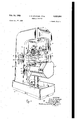
- Fig. 1 i a perspective view of a hobbing, ma-
- Fig. 2 is a sectional view, with portions in elevation, through the, center line of the hob. head and approximately on the line 27-2. of Fig. 3;
- Fig. 3 is a sectional view substantially onthe line 3-3 of Fig. 2, with certain parts in eleva: tion;
- Fig. 4 is an enlarged fragmentary View of a portion, of the right-hand side of Fig. 2. more clearly illustrating. i section, the mechanism for axially shifting the hob and for operating; the stopping mechanism. after a predetermined advanceof thehob and Fig. 5 isa simplified, schematic wiring diagram for the electrical ci-rcuitof the machine.
- the hob head is carried by a member slidably supported in a cylindrical aperture in the vertical column or frame rather than being supported on horizontal ways.
- the machine is of vertical construction and comprises a base A, a vertical column or gooseneck B supported upon the base A, a work head C vertically movable upon verti cally spaced pairs of ways 10, H on the column B, and a tool or hob head D carried by a cylindrical member slidably supported in a horizontal cylindrical aperture in the column B and ad-.- justable therein toward and from the work head.
- the work which may be a gear blank, a shaft to be splined, or the like, is adapted to be rotatably supported in the work head C by having one end supported in a chuck or some other suitable means, not shown, attached to the upper end of the work spindle l2.
- the other end of the work is engaged and supported by a tail center l3 carried by a tail slide l4, the latter being supported for vertical movement toward and from the work spindle upon ways l5, l6 formed on the work head.
- the hob head D is preferably provided with a conventional means F for supplying acutting fluid to the hob and work.
- the work head C is adapted to be reciprocated along the vertically spaced pairs of ways III, H, to cause a work blank carried by the work head to be' moved axially past a hob fixed to the hob arbor I1 and to return the work head to its initial position, by a cooperating lead screw and nut connected to the work head C and the base A, respectively.
- the lead screw is located within the chip guard l8 and is driven at a relatively slow speed in timed relation to the rotation of from the work spindle drive.
- the nut is rotatably supported in a housing 19, bolted to the base A, andis adapted to be rotated at a relatively high speed through the medium of a worm and worm wheel drive by a high speed, reversible traverse motor located within the column B and connected thereto by the shaft 20.
- which carries the hob head D is slidably supported in a cylindricalaperture in the column B and i concentric with respect to the main drive shaft 22 of the
- is adapted to be moved longitudinally within the cylindrical aperture by means of a screw 23 to effect adjustment of the hob toward and from the work spindle, the member 2
- the hob head D comprises a hob head housing 26 having a cylindrical portion 26a pro- ;iecting into a cylindrical aperture in the front end of the member 2
- the hob head D is adapted to be secured in any desired angular position by bolts 21, the heads of which engage within a circular T-groove 28 in the front face of the member 2 I.
- the hob H which is indicated by broken lines in Fig. 2, is keyed to the arbor ll intermediate a shoulder 29, formed on the arbor by a change in its diameter, and a sleeve 3
- Hobs of different lengths may be utilized by employing a spacing washer or sleeve between the hob and the shoulder 29 and/or by utilizing a sleeve 30 of different length from that shown.
- the sleeve'30 is slidably and rotatably supported in a bushing 32 provided in an outboard support 33 which is attached to the hob housing 26, the bushing being held from axial movement by combined retainer and oil seals 34 and 35.
- the arbor IT to the right of the hob as viewed in Fig. 2, is slidably supported in asleeve 36.
- This sleeve is rotatably supported in the hob head housing 26 by pairs of antiiriction bearings 31 and 33.
- the bearings 31 are retained in place between a shoulder in the housing 26 and a nut and washer assembly 39 secured to the outer end of the sleeve 36, an oil seal 49 being interposed between the nut and washer assembly and the adjacent surface of the housing 26.
- the bearings 38 are retained in place between a shoulder in the housing 26 and a plate 4
- a hob arbor gear 42 which is connected to an external flange on the right-hand end of the sleeve 36 by machme screws 43.
- the gear 42 is continuously in meshwith a hob drive pinion 44 formed on the right-hand end of a shaft 45 which is rotatably supported in the housing 26 by antifriction bearings 46 and 41.
- the left-hand end of the shaft 45 has a bevel gear 48 keyed thereto, the gear being held in place by a nut 49 on the threaded end of the shaft 45.
- the gear 48 is continuously in mesh with a bevel drive gear 50 which has an elongated splined hub 5
- of the gear 50 is rotatably supported by a pair of antifriction bearings 52 mounted in a bearing cap or member 53 which is connected by screws 54 to the rear end of the cylindrical portion 26a of the housing 26, a bearing retaining plate 55 and sh ms 56 being interposed between the bearing cap and the hob head housing.
- the rear portion of the inner race of the bearings 52 is engaged by a nut 51 threaded upon the hub 5
- the bearings 52 and their retainers cooperate with the gear 50 to prevent axial displacement of the latter,
- the gear 50 is provided with a cylindrical shaft seal .59 t-oprotect the end of thedrive shaft '22,
- the hob arbor or spindle H in "addition to *its rotation, is given a slow axial movement or feed.
- the hub of the gear -42 is elongated and has a stepped portion 68 on 'which a gear 6 is supported, thegears 4 2-an-d "61 being “conn'e'cted forrotation by a key *tla.
- the gear-61 meshes with a :gear *62 which is COIIHBGTJBCI to rotate with "a gear 63 by meanso'f a pin or rod 64 extending through the two last-mentioned gears.
- "'I'heggears '62 and Bit-are supported upon a'bushing "65 which.
- the bearin retaining ring "H, and hence thegear 10 are 'journalled for rotation upon a reduced diameterportion 73 of th-e'hub of the gear 42 by antifric'ti'on bearings 74 and 15, the bearings being "held in place by a nut is screwed upon the threaded end of the said reduced diameter portion '73.
- the bearingring H has a hollow cylindrical cap member 11 connected thereto by machine screws 18 which extend through "a flange of the .capmemloerandare screwed into tapped holes in the ring H.
- the outer end of this cap member 11 "projects through an opening in an end cover 19 for the hob head housing 26, an oil seal 88 preferably surrounding the cap member adjacent the opening through the cover 79.
- the outer end of the 'cap member 11 is aperlturedtoreceive a cylindrical portion 8
- a flange '83 isvprovided intermediate the threads of the screw 82 and the cylindrical portion 8! thereof, this "flange "being disposed within :a recess in the inner face of'the lender the cap member H "and secured thereto bysorews such as 84 so "that the hub shift-screw 823s rotatable with the cap member 11 andthe "gearlll.
- a nut member 86 Threadably engaged with the hole shifting screw 82 is a nut member 86 which is secured by screws 81 'to the adjacent end of the hob arbor Fl. Also threaded 'uponthe hob shifting screw 82, and disposed intermediate the nut 86 'c and dense 83, "is a second nut member 88, the
- the hubof which is extended and preferably provided with a locking spring 89.
- the outer peripheries of thenutmembers 86 and 88 are provided with splines or gear teeth 99 and 9
- the dock gear 92 is moved-axially until-the gear teeth or splines .99, 93 on the nut EBB- and the lock gear 92 are disengaged, the gear teeth or splines 9 l 9' -on the nut 88 and the lock gear, however, remaining in engagement.
- the outer “periphery” of the lock gear *92 is threaded, and screwed thereonis a pair o'fcontrol *rings or nut members 95 "and F96, the *bores of which are threaded to cooperate with the threads on the lock 'gear 92 so that thering or nut members "may be disposed at any (positions along the length of the'member92.
- a relatively thin cylindrical sleeve 9'! the "end portion of which, adjacent the closed end of the cap member 31.! is turned inwardly 'toprovide a flange 98.
- A' feed control ring 109 is 'slidably disp'osed exteriorly of the cap member 17 and "is connected with the sleeve member 97 by fiatlieaded screws l'lll which extend outwardly from the sleeve 'member '91 passing through bushings I92 between the sleeve I91 "and ring IBIL'the out'er -:ends of the screws being provided with nuts 183.
- the diameters of the bushings I92 are such that they have a sliding fit within the elongated :slots in which they are disposed so that the sleeve member is constrained to rotate with the "cap member and in addition can move axially relative theretoa limited extent.
- the cap member 17 is alsoprov'ided with .a .plu- “ralityof slots I94, of which one only is shown m 2 and .4, in which levers l05a1tepivotal1y mounted with *one 'end ofthe levers extending ring I98.
- the cover member I9 is provided with a radial opening through which passes a portion of a bent lever I09, the lever being provided with a pivot pin I01 which is supported in this opening of the housing 19. r
- the inner or lower end of the lever I06 as viewed in Figs. 2 and 4, is provided with a somewhat spherical enlarged portionor knob I98 which is adapted to engage the control ring I00.
- the portion of the lever on the other side of the pivot I01, and exteriorly of the housing I9, is bent at substantially right angles and has a portion thereof engaging the actuating pin or member of a microswitch I09 which is adjustably supported upon the housing vI9; Intermediate the point of engagement of switch I09 with the lever I06 and the substantially vertical portion of the latter, the lever is provided with an elongated slot through which passes a pin H0.
- the lower end of this pin is secured to the adjacent outer surface of the housing I9 and between the said housing and the lever is disposed a compression spring III, the outer end of the pin I i0 being threaded and pro-
- the construction just deurges the lever I06 to the position as shown in Figs.
- the lever may rock about its pivot I01 when the ring I00 moves to the right as viewed in these figures, thereby operating the switch I09.
- the switch I09 and the portion of thelever I06 exteriorly of the housing I9 are preferably enclosed by suitable cover plates such as H3. i
- the speed of rotation of the feed screw 92 is equal to that of the hob arbor plus or minus a very small increment so that feed [screw rotates relative to the hob arbor or spindle III at a very slow rate thereby causing the latter to be moved axially through the sleeve 36 due to the action of the nuts 86 and 88.
- the hob spindlethus moves axially it carries therewith the control rings or nuts 95 and 90.
- the hob arbor has moved axially a sufficient distance to dispose the control ring or nut 95 in its extreme left-hand, broken line position, as shown in Figs.
- the extent of the shift of the hob and itsspindle prior to actuation of the switch I09 may be adjusted by adjusting the position of the control nut upon the adjusting lock gear 92, the limits of this adjustment for the illustrated machine being indicated by the full and broken line positions of this ring or nut member adjacent the extremities of the threads on the member 92.
- the number of teeth on gears IBI, 62, 93 and I0 may be, respectively, 244, 81, 83
- the screw ,82 is given one revolution relative to the hob arbor spindle for approximately every 10,000 revolutions of the latter and, if there be 10 threads to the inch on this screw, it will be readily apparent that the advance of the hob arbor is in the order of 10 millionths of an inch per revolution of the arbor. Consequently, by suitable adjustment of the control ring or nut 95 upon the lock gear 92, the length of time required for the hob arbor to move axially to the position for actuation of the switch I09 can be madeequal to the length of a work shift or any desired relatively long interval of time so that the machine may be serviced in its normal idle time and its productive time is not interrupted.
- the wear on its surface is equally distributed thereover so that the hobs will perform satisfactory service for longer periods of time than when they are adjusted intermittently as previously mentioned.
- the rate of hob advance and its direction for a given screw 82 may be readily selected by substituting for the gears 6I 62, 63 and I0 others having different numbers of teeth.
- the direction of axial movement of the hob arbor may be readily reversed for a given set of these journalled in the cover member I9 by antifriction bearings I I4, a collar I I5 being disposed between the bearings I I4 and the eccentric portion of the shaft.
- the shaft 01 Exteriorly of the cover member I9, the shaft 01 has a handle member I I9 keyed there- ,to, the outer end of the shaft 91 being threaded and provided with anut I H to retain the handle in place.
- the inner, or left-hand, portion II8 of the shaft 61 is concentric and is journalled in 9, a: bore, provided, in the housing 26' and between the, portionszfidand "'8' the shaft BT has a concentric. portion v I19 oflarger' diameter forming shoulders abutting the housing 26 and the bearings. 69,.
- Theiportion I I 07' of the'shaft 61 ispro-vided'with two. recesses spaced 180" apart with which a springpressediball 'detent I 20selectively cooperatesto retain the shaft in either of two posi tlons corresponding with the engaged" and dis-- engagedlpositions offgears 62 andi63"with respect tothe gears 6
- rotation of the hob arbor, or spindle, I!- also causes the latterto be slowly movedior, shiftedaxially:
- the hob arbor has, moved" axially the predetermined distance,,as.determined by the setting of the controllnut 95; theswitch I09is actuated, as above described terminating operation of the, machine and "lighting, the Signallamp L.
- the operator rocks the handle. II'Ii through 180 tothe second position thereof thus disposing the eccentric-portion at, its lowermost position and disengaging the. gears.
- the spring detent I20 holds the shaft 5.7; an'dhence thegears 62; and 63'; in either of the twoabove-described positions: after'beingmoved theretwby th'e-operator' rocking the handle Illi through I an arc of 10 the two positions of the handle being indicated by broken lines in: Fig; 3;
- the operation of the* machine is electrically controlled.
- switch I-25 for controlling thedirection": of the operating cycle; afeed on-or'lf" switch I26, and a switch I21 for automatically terminating the feed prior to stopping the rotation of the work and hob.
- the start-and stop switches are prefer-ably of the push button type, while the switches I24; I25; IIZ-li and.
- Theother side of" the work head is preferably provided with two spaced stops on abutments, notshown, adapted to actuate an overtravel lim it switch mounted on the column B.
- the electrical controrsystem for the machine is so arranged that'the cycles of'operation of the machine, may bestarted; with the, worklhead C in either of, its normally extreme vertical positions. Thattisi to; say, with the'switch; I25: set inonezposition; circuits are-set up: IZO -GflBQtIthG cycle? of: operations such that the work: Iheaolf C moves in an upward direction during the hobbing operation, and with the switch I25 set in the other position thereof, the work head C is moved downwardly during the hobbing operation.
- the selector switch I24 controls the direction of rotation of the motor driving the hob arbor and the work so that rotation in either direction may be eifected as desired.
- the switch I21 enables the feed of the work to'be automatically terminated a predetermined time before the stopping of the hob arbor in order to provide for clean up of the work, while the switch I25 enables the feeding movement of the machine to be terminated at any time without interrupting the rotation of the hob and work.
- This latter feature is advantageous in setting up the machine or for checking its operation.
- the machine is provided with the usual suitable safety switches, such as the previously-mentioned overtravel limit switch for the work head to prevent the latter from being moved beyond a predetermined point in the event the switch operated by the stops I33, I3I should fail to operate.
- Fig. 5 of the drawings represents a simplified, schematic wiring diagram showing the manner in which the above-mentioned switches are connected to effect the previously-mentioned operations.
- the cut motor I32 which efiects rotation of the hob arbor and work spindle and feeding movement of the latter, as well as the rapid traverse motor I33 are alternating current motors of the 3-phase reversible type.
- the power supply lines LI, L2 and 'L3 are connected to a source of alternating current of the 3-phase type, the motors I32 and I33 being connectible therewith by operation of the switches I24, I25 and certain contacts of various relays, the coils of which are represented in the lower part of Fig.
- wires I34 and I35 which forms the control portion of the circuit, this portion of the circuit being energized through wires I34 and I35 connected respectively with the power supply lines L2 and LI.
- the wires I34 and I35 may be supplied with electrical power through a transformer connected be tween these wires and the power lines LI and L2 instead of connecting the wires directly to the power supply lines.
- a conventional cutout switch may be employed in the power supply circuit connected with the power supply lines LI, L2 and L3 if desired.
- the machine is thus conditioned to performits cycle of operations by effecting a rapid traverse of the work head upwardly to a position which disposes the work adjacent the hob, the work head thereafter movin upwardly at the relatively slow feeding rate with the hob rotating clockwise, as viewed in Fig. 1.
- the work head 0 At the beginning of the cycle of operation the work head 0 is at its lowermost or down position so that switch I36 operated by the stops I30 and I3I has its contacts Ia closed and its contacts I331) open. Likewise, the contacts I31a and I311) of the switch I31, which is actuated by the stop I29, are respectively closed and opened.
- the machine is started by depressing the start push button I22, thus causing the latter to bridge across the stationary contacts I38, I39 and I45.
- This closes a circuit from the wire I34 through the normally closed contacts I4I, of the previously-mentioned overtravellimit switch, through the normally closed, stop switch I23 to a wire I42, thence through a wire I43, the now depressed start switch I22 and wire I44 to a wire I45 connected with one terminal of the coilof a relay I43.
- relay I46 when the start switch I22 is released and returns to its initial position, the resulting deenergization of relay I46 does not deenergize relay I53. Moreover, as soon as the start switch has returned to its initial position relay I46 is again energized through the now closed contacts I53d so that the contacts I43a, I460 are again closed and the contacts I461) opened.
- the contacts I53a, I531), and I530 are respectively disposed intermediate wires, I55 and I56, I51 and I58, I59 and I60 which connect the rapid traverse motor I33 with the power supply lines LI, L2 and L3 through the contacts I25a, I251) and I250 of switch I25.
- the latter contacts being disposed in their lowermost positions as previi-L ouslyr mentioned; the rapid traverse motor.
- I33 1 is energized for --rotation' in ardirect-iom which effects rapid movement-oi" the-'worlt head i'n an upward direction. Current is also supplied: from: the Wires. I56, I58 through. the normally closed contacts "In".
- the stop IZB thereon engagesthe switch I 31 to again-closezthe contacts: I'STIaiand open: the contacts 53 7b. This has: no effectaon the circuit other than to prepare. itfor a new: operation;
- thestop I30 engages: the switch- I36: again closing its. contacts: Iiit'w and" opening it's contacts 136?). Opening of the contactsltfib-de ene ergizes the relay H8; thereby openingcontacts 18m; W82), H30 and I -ISdi so thattthe solenoid I65 of the brake and: ther rapid traverse.
- motor I33 are deenergized with the result: that movement of the work headis terminated;
- The. operation may be repeated with a new workpiece :by: simpl y positioning thelatten'in the worlc head and' operating-the startbutton, and
- the work head may be traversed to its lowermost position, as above described, by operation of the start button I22. If, however, the operator should now position a new workpiece in place and start the machine again by actuating the button I22,- the work head simply rapidly traverses to bring the work adjacent the hob, as above described.
- the relay I65 is not now energized since the circuit through the contacts I09a is now open.
- the cut motor I32 is not energized so that hob'bing cannot be effected with the worn hob and the latter must be replaced as previously described.
- the switch I24 should be placed in its intermediate position so that the contacts I24a, I24b and I240 are disposed as indicated in Fig. 5. This prevents the cut motor I32 from being energized while Work of replacing the hob is being eiiected.
- the hob arbor is returned to its initial position by. rocking the handle IIG through 180 to disengage the gears 62 and 63 from the gears BI and 10 and then rotating the screw 82 through means of a wrench or other tool applied to the polygonal head 85.
- the nut 95 moves from engagement with the lever I so that the spring 99 returns the sleeve 91 and control ring I00 to their initial positions so, that the lever I06 rocks clockwise, as viewed in Figs. 2 and 4. This closes the contacts I09a and opens the contacts I09b of the switch I09. Closing of the contacts I090, does not, however, result in energization of the cut motor I32 since the switch I24 has been moved to circuit'opening position.
- the switch I24 is again actuated to position its contacts I24a, I241) and I240 into engagement with the lowermost cooperating contacts, whereupon the motor I32 will be energized, since the contacts I090, are now closed so that the relay I65 is energized therethrough. It will be apparent, therefore, that a hobbing operation once started is carried to completion and is not interrupted while work is being hobbed. Nevertheless, the machine is so controlled that a new hobbing operation cannot be commenced until the worn hob has been replaced.
- the machine may be operated so that the cutting operation will be in the conventional manner, but the direction of feed will be downwardly, by merely reversing the switches I24 and I25 from their positions for effecting hobbing while the work head is fed upwardly. This will place the contacts I240, I24! and I240 of the former switch in engagement with the uppermost stationary cooperating contacts of that switch, and the contacts I25a, I251), I250, I25d, I25e, I25j and I25g of the latter switch in engagement with their uppermost stationary con tacts.
- Closing the contacts I18d provides a holding circuit for the relay I18 about the start switch I22 so that the relay I18 remains energized when the start switch is released and returns to its initial position.
- Closing of the contacts I18a, I18band I180 respectively connect the wires I55 and I50, I51 and I56, I59 and I60.
- the rapid traverse motor I33 is energized for rotation in a forward direction.
- current is supplied through the normally closed contacts I6Ia, I6 I b energizing the solenoid I64 of the brake with the result that the rapid traverse motor now moves the work head rapidly upward.
- the stop I29 engages and operates the switch I31, thus moving the contacts I310 to open position and the contacts I31b to closed position. This prepares the circuit for subsequent operation but does not initiate operation of the out motor at this time since the relay I46 has not been energized and hence the contacts I46a are open so that no circuit can be completed to the relay I65.
- the stop I3I engages and actuates the switch I36, thus moving the contacts I360 to open position and the contacts. I36b to closed position.
- Opening the contacts I360 interrupts the circuit through the relay I18 deenergizing the latter and thereby opening the contacts I18a, l18b, I180, I18d with the result that the rapid traversemotor is stopped and the brake applied Relay [13' amm so .,that stlie movement ofthe i work head terminates.
- a workpiece maynow be positioned.inthelwork head i and upon again depressing the start button 122, a cirouit isn-completedgfromw the wire I42 through-the wire l 4 3, l the start switch .i [2 2 in! its Idepressed ,-position, wire I44 and M5 -,to and through relay! L45; the wire lfd'l and 1 the-.contact I25g-which .isnow iii-engagement its upper rstationarymcontact, to and ;throu h the ..-now closed :contact, 1361), wire) I 48, contacts [49mm I50 tto the-wire-t35. l-Relay.
- the switch J31 is ractuatedby the stop l29,- thescut motor 11 32151521101] energized-since the.
- the machine can likewise-heoperated to effect fc1imb" "cutting; or jhobbing but with tithe feed being prodnced 1 by downwardmovement of the work headCTby utilizing, an idler gear" in fthe feedjchangegears and byrever'sing thenosjitions g5, floflthe, switches ,I 24, and] l 26.
- the cycle offpperw tion is the same as that described with respect to conventional cutting, feed down and hence will not be repeated.
- the switch I09 operates to prevent further hobbing operations after the hob has reached its extreme of axial movement and the cycle of operation has been completed.
- the machine is profeed of the latter thereby effecting a cleanup of the end of the cut.
- This feature is especially useful when splining or the like is being out since it insures that the ends of the splines will all lie in the same transverse plane.
- the switch I21 is positioned so that its movable contacts I21a and I21b engage the left-hand stationary contacts adjacent thereto as viewed in Fig. 5. Let it be assumed that the operation will otherwise be conventional cutting or hobbing with the feed up.
- the machine is started, as before described, by depressing the start button and operates as mentioned above to rapid traverse the work adjacent the hob.
- the switch I31 is actuated, as previously described,
- the contact I81a is connected by a wire I88 to "the contact I21b which is now closed with the cooperating stationary contact connected by a wire I89 to the wire I48.
- the cut motor I32 remains in operation 20 for a predetermined period of time after operation of the switch I36, the length of this period being determined by the relay I81 which is a timing relay, preferably adjustable, and operates the contact I81a as hereinafter described;
- switch I36 at the upper limit of travel of the work head has, as mentioned before, closed the contacts I361).
- This energizes the timing relay I81 through the now closed contacts I460, the wire I90, the coil of relay I81, wire I95, contacts I21a, I25g and I361) to wire I48.
- the relay I81 Since the relay I81 is a timing relay, it does not operate its contact I81a immediately upon energization but only at the end of a predetermined time interval thereafter.
- the timing relay I81 is of conventional type and is adjusted to provide the desired amount of rotation of the hob and work after termination of the feed of the work head. This time interval may, for example, be in the orderof the length of time required for one complete revolution of the work after termination of the feeding.
- relay I81 When the predetermined time interval for which relay I81 is set has elapsed, this relay moves its contact to circuit opening position thus deenergizing relay I46. Deenergization of relay I46 opens its contacts I460. and I460 thereby deenergizing relays I65, I84 and I81 so that the motor I32 is deenergized.
- the relay I6I remains energized for a short time interval after the deenergization of the motor I32 so as to insure that the brake is not applied before the desired rotation of the work and hob have been completed, thus insuring against incomplete cleanup operation.
- relay I6I is provided with another set of contacts I6Ie which are normally open but which are closed upon energization of relay I6I to provide a holding circuit for the latter. This circuit extends from the wire I42 through the contacts I6Ie,
- the energization of the timing relay I94 is under control of the normally open contacts c ca'c'zecc' 21 I6. I:e:an:apair o'finormaily; elosed'contaots 6d of .ir'elay I46. "Gonsequently, whenthe 'conta'cts I6 I care closed and while the-relay I46 is still energized: that is, "prior; to the deenergization of the' motor I32,-thetiming relay I 94 is'not ener- "gized since the "contacts 446d are held open.
- the relay I81 has operated to moveits contact IBM" to circuit *openin g position thereby 'deenergizingv 'relays I46, I85 and I65- so that the motor I 32 "is deenergized; the circuit to the relay I94 is M thencompleted through the -'now-closed contacts Ifidiof relay "Ifiythe circuit-extending from the wire I -I 42 I through the now -closed contacts IBIe, wire I96,.normally closed contacts I46 d; relay "I94, "wire 193, “contacts 12-111, 125g, and I3Iibito wire I48.
- This-timedelay inter- "posed 'to'insure that the brake is no-t prematurely applied while the desired rotationim-parte'd I by "thecut' motorto the work and the arbor is still continuing, i'as by coasting, after the motor is deenergized.
- reopens itscon-tacts t6 I e so that the timing relay I94 isdeenergized;”restoring the circuitto the condition-such that" the I work may now beremoved from the work head, the- -machine -being returned to its "initial positiorrbyagain operating the; start” button I22, as described above I under ""Conventional cutting; feed up-.
- Wi th "-the ma'chine” thusset up the initial Aactuation of the :start button I 22 causes the: .work
- the operation of the swi-tch I36 toclosed position has energized thesrelay I6 I through the circuit ektendingfrom' the wire -I42, the -now-"c1osed con tacts I46c,- 'wire- I90, wire I9 I the 'coil" ofr the 'relay I 6 I contact I 2 6a, wires I 92 and I 93; contact 121d, wire I I 82,--contacts I 25) and -I 36a -to the wire -I 48.
- the cleanup feature above described may also be employed with cnmwhobbingwith the feed being? either up or down i n the same-*manneras described for conventional cutting or bobbing with feed -up or down?
- the switch I09 actuated by the axial-movement of the hob arbor prevents further hobbingppera- I tions when the hob a'rborfhas moved to its'extremeadvanced position.
- the solenoid I64 'of the brake. is energized so that'both the feed screw and nut may freely rotate with the result that there is no feeding of the work head and hence the machine, will continue in this condition until the switch I26 is positioned to bring its contact I260; into engagement with its lower stationary contact, which ,is connected with the wire i92, thereby deenergizing the relay I6I so that the brake is reapplied and feeding may be effected, the operation of the machine then continuing in the same manner as before described.
- This no-feed feature may likewise be employed with conventional cutting or hobbing with feed in the downward direction by setting the switches I24 and I25 for such operation but with the switch I26 set so that its contact I260. closes the circuit to the wire I91.
- the machine will then operate as previously described for Conventional cutting, feed down until the work head has brought thework adjacent the hob at which time the rapid traverse motor I33 is deenergized and the cut motor I32 is energized, as previously described.
- the no-feed feature may also be employed with climb cutting or hobbing.
- thefeed may be interrupted during a cutting or hobbing operation of either the conventional or climb type by simply actuating the switch I26 to position its contact I 26a in engagement with the upperstationary contact connected with the wire I91.
- the relay I46 When cutting or hobbing is in progress the relay I46 will be energized so that contacts I46c are closed and hence the actuation of switch I26 will result in energization of relay I6I thereby terminating the feed without interrupting the rotation of the hob and work. Feeding may be resumed by simply reversing the position of switch I26.
- Both the start switch I22 and the stop switch I23 are of the push button type and include ferrules I98 and I99, respectively.
- the ferrule I98, associated with the start button I22 is adapted to secure the latter in an intermediate position
- the start button I22 is initially depressed into engagement with its contacts I36, I39 and I40, and the ferrule I98 is adjusted so that when the button is released by the operator, it will be held in its intermediate position as indicated by the dotted lines in Fig. 5.
- the initial depression of the start button I22 closes the circuit from the wire I42 through the wire I43 and start button I22 to the wire I44, thus energizing relay I46 when the machine is'set for Conventional cutting, feed up.
- relay I46 closes its normally opencontacts I460 thus energizing relay I53 through the last-mentioned-contacts, wire I5I, wire I52, the coil of the relay I53, wire I54 and contacts I25d, I31a, wire I55, contact I25) and contacts I36a,'the circuit extending to the wire I48 and through the contacts I49a,.l50a to the wire I35.
- relay I53 is energized, closing its normally open contacts I53d and providing a holding circuit for the relay I53 so that when the start button I22 is released the resulting deenergization of relay I46 does not result in deenergization of relay I53.
- the relay I46 is not again energized since it will be remembered that the start button I22 is now held in its intermediate position.
- the energization of the relay I53 has closed its contacts I53a, I53b, and I530 thereby energizing the motor I33 effecting rapid traverse of the work head to bring the work adjacent the hob, whereupon the switch I31 is actuated to open its contacts I31a and close its contacts I311). This deenergizes the relay I53 so that the motor I33 and movement of the work head stop.
- the circuit to the relay I65 is not completed at this time however, since the start button is held in its intermediate position. Consequently, the motor I32 is not energized so that the work head does not move and the hob and work are not rotated. This enables the hob to be adjusted relative to the work and to efiect such other adjustment of the mechanism as is necessary.
- the machine may be started upon the remaining portion of its cycle by simply returning the ferrule I98 to its initial position thus releasing the latter which is then depressed again.
- This actuation of the start button I22 completes a circuit through the button in its depressed position and through the wire I44, contacts I69a, wire I66 and wire I61 to the relay I65 and from the latter through the contact I25e, contacts I31b, which are now closed, wire I55, contact I251, contact I36a to the wire I48,
- the relay I65 is therefore energized closing its contacts a, I65b, I65c and I65d.
- the latter contacts provide a holding circuit for the relay 7 I65 maintaining the latter energized when the start button is released, while the contacts I65a, I65! and I650 effect energization of the cut motor I32 so that the hob and work are rotated and the work head is moved vertically at the feeding rate, the operations continuing as previously described.
- the machine may likewise be operated by employing the ferrule I98 to hold the start button I 22 in an intermediate position when the machine is employed for conventional cutting, feed down.
- the start button is initially depressed, the ferrule not yet being adjusted to hold the button partially depressed, with the result that the work head is rapidly traversed to its uppermost position in the usual manner.
- the ferrule is then actuated to'hold the start button in its intermediate position.
- Th'eferrule' l99. provided .for the stop button [2311s adapted to hold the latter in its. depressed orxIopen position. Hence, this stop button may be... depressed and the ferrule actuated to hold it ingithatfposition whenever it isdesired to work upon the. machine. or otherwise ,prevent operation- .of'jany ofthe parts thereof; since. the stop button I23! controls.- energiz'ation off the entire control circuit.
- SUMMARY Variations may be 1 made; in: the; types of switchesxiand relays employed :andncertain: of the features 'describedrmay: be omitted: In all cases, however; thatfis; Whether the 'cutting 'or 'hobbing be'flconventionalfor climb. and-withrfeed .up
- a hob head-for any electrically controlled hobbing machine driven by; an electric motor, the said head comprisinga hob arbor; means" journalling said hob-arbor'for rotary and axial move ments, means adapted; to' be rotatedjand including gearing operatively connected "to said arbor adjacentone end of the latter for producing rotationand-axial movement of the. arbonupon 'energization' of the motor of the bobbing, ma-
- chine thedistance-of the said axial movement for each-hobbing operation performed by a: hob on said arbor beingasmall fraction ofthe useful length of 'the.hob;a-first member connected with said hole arbor intermediate said gearingandrthe adjacent end ,ofsaid-arbor for movement with thezlatter, a second member supported; adjacent saidxone end of; said arbor forlimitedgmovement relative to said arbor, means adjacent eitherendof 'said'second member adapted to be engaged by said" first 'memb'er and lto, thereby move the said second. member, an' electrical switch supported adjacent, the. said one end.
- a hob headfas defined ,inclaim SandfWherein the connection of saidhfirst member. to said arbor includes-means for securing thesaid. first member tothe arborat different.axialpositions therealong to. thereby. select the. extent pof axial movement of 1 the arbor priorto actuationcofzsaid switch.
- a hob head for an electrically controlled hobbing machine comprising a hob arbor, means journalling said hob arbor for rotary and axial movements, means adapted to be rotated and'in'cluding gearing operatively connected to said arbor adjacent one end of the latter for producing rotation and axial movement of the arbor, a first member connected coaxially with said hob arbor'intermediate said gearing and the adjacent end of said arbor for move- ,ment with the latter, a second member supported in radially spaced coaxial relationship with re- 'spect to said one end of said arbor for limited axial movement with respect to said arbor, means normally urging said second member in one direction of its axial movement, means adjacent either end of said second member adapted to be engaged by said first member and to thereby axially move the said second member in the direction opposite to that in which it is urged, an electrical switch supported adjacent the said one .end of the arbor and adapted to be connected in the control circuit for the hobbing machine, and
- connection of said first member to said arbor includes means for securing the said first member to the arbor at different axial positions therealong to thereby select the extent of axial movement of the arbor prior to actuation of said switch.
- a hob head for a hobbing machine having electrical means including a motor and a control circuit for effecting operation of the machine, the said hob head comprising a housing, v
- a hob arbor means in said housing journalling said hob arbor for rotary and axial movements with respect to the housing, a shaft rotatably supported in said housing and adapted to be operatively connected for rotation by said motor,
- means including gearing within said housing adjacent one end of the latter and operatively connecting said shaft and arbor for producing rotation and axial movement of the latter when said shaft is rotated, means adjustably connected to said hob arbor intermediate said gearing and the I adjacent end of said housing for movement with the arbor, an electrical switch supported on said housing adjacent the said one end of the arbor, the said switch being connected in the control circuit of the hobbing machine to control the energization of said motor, and means cooperating with said switch and the said means connected with the arbor to actuate the said switch when 1 the arbor has moved axially a predetermined dis- 11.
- a hobbing'machine having a rotatable and axially movable hob arbor
- an electrically controlled hobbing machine having a rotatable and axially movable hob said member to operate the switch when the hob arbor has moved axially a preselected distance corresponding to the adjusted position 'of the member, and an electrical circuit controlled by ,the actuation of said switch, the said circuit including relay means establishing circuit relationships in response to actuation of said switch for preventing the beginning of a new hobbing operation while permitting a hobbing operation in progress at the time of the switch actuation to continue to completion.
- a hobbing machine comprising a hob arbor
- a work support means including an electric mo tor for rotating said arbor and support and to produce relative movement between said arbor and support axially'of the axis of said work support, means including gearing connected with said hob arbor adjacent one end of the latter to axially shift the arbor in response to rotation thereof, an electrical circuit for controlling the energization of said motor, manually'operable switch means in said circuit for initiating a hobbing operation, means in said circuit for automatically deenergizing said motor when a hobbing operation has been completed, switch means in said circuit adapted when actuated to prevent energization of said motor, means including a member adjustably connected with said hob arbor intermediate said gearing and the adjacent end of said arbor for actuating the lastmentioned switch means when said hob arbor has moved axially a predetermined distance, and
- a hobbing machine as defined in claim 14 UNITED STATES PATENTS and further comprising an indicating means in Numb r Na e Date said control circuit and controlled by actuation 1,757,929 Shaw et a1 May 6, 1930 of said last-mentioned switch means for indi- 1,735,395 h i; a1 Dec, 16, 1930 eating a predetermined distance of axial move- 2,374,254 Zimmermann Apr. 24, 19 15 ment of said hob arbor. 10 2,481,974 Bradner Sept. 13, 1949 OTIS E. STAPLES. 2,484,856 Purvin Oct. 18, 1949 ANTHONY J. BENT- 2,537,967 Carlin Jan. 16, 1951
Landscapes
- Engineering & Computer Science (AREA)
- Mechanical Engineering (AREA)
- Gear Processing (AREA)
Description
Feb. 24, 1953 o. E. STAPLES ETAL 2,629,290
HOBBING MACHINE Filed Oct. 27, 1948 5 Sheets-Sheet l INVENTOR5 0775 5 572. 255 1 By A/wwo/vyJEA r 74W ,25 I
I, 1 ATTORNEY Feb. 24, 1953 o. E. STAPLES ETAL HOBBING MACHINE 5 Sheets-Sheet 3 Filed Oct. 27, 1948 IN VEN TORS 077.5 E Emma-s y ANr/ /MYJBE/Yr Man, ,3 W, 4
HOBBING MACHINE Filed Oct. 27, 1948 5 Sheets-Sheet 41 vm mm M m a w mm M x 1% wfimz m N. A mm 73% Mm tw l W I vm ml. rain.. I! Q 5 l I 5 .f 45 \1 ms 3 R f QWFIHHQL I a I 8 71 Q t Wm Om 8 I 8P =2 l n2 wv .ITIEE m9 5? F Nw l S? A Feb. 24, 1953 Filed Oct. 27. 1948 O. E. STAPLES ET AL HOBBING MACHINE 5 Sheets-Sheet 5 WM DM I Patented Feb. 24, 1 953 UNITED STATES PATENT OFFICE OtisE. Staples, Euclid, and Anthony J. Bent, Willoughby, Ohio, assignors. to The Cleveland HobbihgMachine Company, Cleveland, Ohio, a
corporation of'Ohi'o Application October 27, 1948, Serial No. 56,726
15 Claims.
The present invention. relates to bobbing machines and, more particularly to bobbin machines of the, axial feed type. as distinguished from tangential feed type hobbingmachines.
In the operation of. bobbing; machines of the axialfeed type it has, heretofore been customary to. periodically advance the hob thatis move the hobntangentially of the work spindleafter a, number of blanks, have; been cut so as. tobring anew section of the hob into cutting position. This practice does not make full, use. of the hob since, inv order to .insurethat an. entirely new section thereof is in cutting position, it is necessary to leavean unused portion between thesection that 1 135111517.- been used and the next section to be-uti- .lized. These portions.intermediatesuccessive ottings have performed no, or very little, cutting so that the.- wear, etc., incident to the.- cutting operationbeing performed is not uniformly distributed over the usable or effective length of the hob. More recently the. hob. has been continuouslyadvanced or moved tangentially of the work. during the cutting operation in such amannet that the hob. is. advanced an amount equal toits usable or effective lengthonceduringsome relativclylong period. of time, such as a work day,.ahalf day, or the like. At. theend of each period the, hob is replaced, if necessary, and. the direction of advance reversedor the mechanism returned to its: original position and thencycle repeated;- 7
The principal object of. the present invention .isthe provision of .a. novel and improved; hob.- .bing machine and hob head, of the character referred to, comprising means for effecting a; continuous advance of the hob tangentiallyof the work, during, the cutting operation, which means includes novel mechanism, for stopping, the machine at the completion of the particular cut or cycle of operations being performed at the time the hob reaches a predetermined point in its advance tangentially-of the work.
Another object of the invention is theprovision of a novel and improved hobbingmachine-and hob head as set forth in the preceding object and wherein the mechanism for stopping themachine, in response to-a predeterminedtangential advance of' the hob,pis readily :adaiustable to permit: selection of the extent. of that advance,
wherebythe machine and mechanism-are: readily hob head as. set forth. in. the two. preceding objects wherein the mechanism responsive to tangential or axial advance of the hob is conveniently located adjacent the end of the. hob head housing so that it is readily accessible for servicing and adjustment.
An additional object of the invention is the provision of a novel and improved hobbing. machineand hob head as set forth in any of the preceding objects and wherein the mechanism for stopping; the machine at. the completion of the predetermined advance of the hob includes a, signal for automatically indicating that, the predetermined point in the tangentialadvance of the hob has been reached.
The invention also has. a an object. the. provision of a noveland improved bobbing. machine and hob head. as. set forth in the, preceding ob.- jects wherein the mechanism responsive to tancntial or axial advance of the hob is relatively economical to-manufacture, easy to install andis solocated in the machine that itdoes not require increase in the sizev of the hob head adjacent. the
hob carried thereby.
The invention further reside in certain con.-
; structionsand combinations and arrangements of parts and further objects and advantages will be: apparent fromv the following description of ithepreferred embodiment, described with reference to the accompanying drawings, forming a part; of this specification, in which similar reference characters d ignate correspondi g, part and. in which:
Fig. 1 i a perspective view of a hobbing, ma-
chine embodying the. present. invention;
Fig. 2 is a sectional view, with portions in elevation, through the, center line of the hob. head and approximately on the line 27-2. of Fig. 3;
Fig. 3 is a sectional view substantially onthe line 3-3 of Fig. 2, with certain parts in eleva: tion;
Fig. 4 is an enlarged fragmentary View of a portion, of the right-hand side of Fig. 2. more clearly illustrating. i section, the mechanism for axially shifting the hob and for operating; the stopping mechanism. after a predetermined advanceof thehob and Fig. 5 isa simplified, schematic wiring diagram for the electrical ci-rcuitof the machine.
Although. the invention is susceptible of. various modifications and alternativeconstructions, it is herein shown and described as embodied in a bobbing machine similar to. that; shown United states Patent No. 2,307,428,, issued. Janucry 1943, except that: the. shape of, the machine i slightly different, some of the. electrical control the hob and work spindles machine.
devices have been relocated, and the hob head is carried by a member slidably supported in a cylindrical aperture in the vertical column or frame rather than being supported on horizontal ways.
Generally speaking, the machine is of vertical construction and comprises a base A, a vertical column or gooseneck B supported upon the base A, a work head C vertically movable upon verti cally spaced pairs of ways 10, H on the column B, and a tool or hob head D carried by a cylindrical member slidably supported in a horizontal cylindrical aperture in the column B and ad-.- justable therein toward and from the work head. The work, which may be a gear blank, a shaft to be splined, or the like, is adapted to be rotatably supported in the work head C by having one end supported in a chuck or some other suitable means, not shown, attached to the upper end of the work spindle l2. The other end of the work is engaged and supported by a tail center l3 carried by a tail slide l4, the latter being supported for vertical movement toward and from the work spindle upon ways l5, l6 formed on the work head.
The hob spindle or arbor I! i rotatably supported in the hob head D in a manner hereinafter more specifically described and during operation of the machine is rotated in timed relation to the rotation of the work spindle l2 by a cut motor located in the lower part of the column B and operatively connected to the respective spindles in a manner similar to that disclosed in the aforesaid patent and hence is not here shown nor described in detail. The hob head D is preferably provided with a conventional means F for supplying acutting fluid to the hob and work.
The work head C is adapted to be reciprocated along the vertically spaced pairs of ways III, H, to cause a work blank carried by the work head to be' moved axially past a hob fixed to the hob arbor I1 and to return the work head to its initial position, by a cooperating lead screw and nut connected to the work head C and the base A, respectively. The lead screw is located within the chip guard l8 and is driven at a relatively slow speed in timed relation to the rotation of from the work spindle drive. The nut is rotatably supported in a housing 19, bolted to the base A, andis adapted to be rotated at a relatively high speed through the medium of a worm and worm wheel drive by a high speed, reversible traverse motor located within the column B and connected thereto by the shaft 20. These mechanisms are likewise similar to those shown in the aforementioned patent to which reference is had for the detail-s thereof. r
The cylindrical member 2| which carries the hob head D is slidably supported in a cylindricalaperture in the column B and i concentric with respect to the main drive shaft 22 of the The member 2| is adapted to be moved longitudinally within the cylindrical aperture by means of a screw 23 to effect adjustment of the hob toward and from the work spindle, the member 2| being clamped in any adjusted'position by a clamp mechanism actuated by a clamp screw 24 and being prevented from rotating in the cylindrical aperture by a key 25. The hob head D comprises a hob head housing 26 having a cylindrical portion 26a pro- ;iecting into a cylindrical aperture in the front end of the member 2| and through the medium 4 of which the housing 26 and, in turn, the hob head D are rotatably connected to the front end of the member 2| concentric with the axis of the shaft 22. The hob head D is adapted to be secured in any desired angular position by bolts 21, the heads of which engage within a circular T-groove 28 in the front face of the member 2 I.
The hob H, which is indicated by broken lines in Fig. 2, is keyed to the arbor ll intermediate a shoulder 29, formed on the arbor by a change in its diameter, and a sleeve 3|] which is retained on the arbor by a nut 3| provided on the threaded outer end of the arbor. Hobs of different lengths may be utilized by employing a spacing washer or sleeve between the hob and the shoulder 29 and/or by utilizing a sleeve 30 of different length from that shown.
The sleeve'30 is slidably and rotatably supported in a bushing 32 provided in an outboard support 33 which is attached to the hob housing 26, the bushing being held from axial movement by combined retainer and oil seals 34 and 35. The arbor IT, to the right of the hob as viewed in Fig. 2, is slidably supported in asleeve 36. This sleeve is rotatably supported in the hob head housing 26 by pairs of antiiriction bearings 31 and 33. The bearings 31 are retained in place between a shoulder in the housing 26 and a nut and washer assembly 39 secured to the outer end of the sleeve 36, an oil seal 49 being interposed between the nut and washer assembly and the adjacent surface of the housing 26. The bearings 38 are retained in place between a shoulder in the housing 26 and a plate 4| sefilliled to the housing by machine screws or the The right-hand portion of the hob arbor or spindle H, as viewed in Fig. 2, is splined, and
slidably keyed thereto is a hob arbor gear 42 which is connected to an external flange on the right-hand end of the sleeve 36 by machme screws 43. The gear 42 is continuously in meshwith a hob drive pinion 44 formed on the right-hand end of a shaft 45 which is rotatably supported in the housing 26 by antifriction bearings 46 and 41. The left-hand end of the shaft 45 has a bevel gear 48 keyed thereto, the gear being held in place by a nut 49 on the threaded end of the shaft 45. The gear 48 is continuously in mesh with a bevel drive gear 50 which has an elongated splined hub 5| in which is received the splined end portion of the drive shaft 22. The hub 5| of the gear 50 is rotatably supported by a pair of antifriction bearings 52 mounted in a bearing cap or member 53 which is connected by screws 54 to the rear end of the cylindrical portion 26a of the housing 26, a bearing retaining plate 55 and sh ms 56 being interposed between the bearing cap and the hob head housing. The rear portion of the inner race of the bearings 52 is engaged by a nut 51 threaded upon the hub 5| -of the gear 59 and a suitable oil retainer or seal 58 is provided between the nut 51 and the rear portion of the bearing cap 53. The bearings 52 and their retainers cooperate with the gear 50 to prevent axial displacement of the latter,
the hob head housing 23 and the cylindrical hob head toward and from the work spindle.
The gear 50 is provided with a cylindrical shaft seal .59 t-oprotect the end of thedrive shaft '22,
see ers when it projects Piorwardly -.=o"f the gear =39, and
to prevent the entrance 'of foreign matter into the splines :"of' the gearand shaft.
As mentioned heretofore, the hob arbor or spindle H, in "addition to *its rotation, is given a slow axial movement or feed. For this purpose the hub of the gear -42 is elongated and has a stepped portion 68 on 'which a gear 6 is supported, thegears 4 2-an-d "61 being "conn'e'cted forrotation by a key *tla. The gear-61 meshes with a :gear *62 which is COIIHBGTJBCI to rotate with "a gear 63 by meanso'f a pin or rod 64 extending through the two last-mentioned gears. "'I'heggears '62 and Bit-are supported upon a'bushing "65 which. .in turn, i rotatably "supported upon a cylindrical portion 66 of a shaft 61 by'antifriction bearings 68 and 69. The portion 66 is eccentrically disposed'with respect to the axisof the shaft 61 sothat the gears "62 "and '163 may "be-placed inmesh with or disengaged fromthe gears'fil and 19 respectively as hereinafter described.
The 'gear 19, which is adapted to 'mesh with the gear 63, is mounted upon a bearing retainingring 1|, the ring being connected for rotation-with the gear 19 by a key 12. The bearin retaining ring "H, and hence thegear 10, are 'journalled for rotation upon a reduced diameterportion 73 of th-e'hub of the gear 42 by antifric'ti'on bearings 74 and 15, the bearings being "held in place by a nut is screwed upon the threaded end of the said reduced diameter portion '73. The bearingring H "has a hollow cylindrical cap member 11 connected thereto by machine screws 18 which extend through "a flange of the .capmemloerandare screwed into tapped holes in the ring H. The outer end of this cap member 11 "projects through an opening in an end cover 19 for the hob head housing 26, an oil seal 88 preferably surrounding the cap member adjacent the opening through the cover 79.
The outer end of the 'cap member 11 is aperlturedtoreceive a cylindrical portion 8| of a hub "arbor shifting screw "82 which extends within the cap'member and isfreely received in an axial bore provided .in the adjacent end or the hob arbor or spindle H. A flange '83 isvprovided intermediate the threads of the screw 82 and the cylindrical portion 8! thereof, this "flange "being disposed within :a recess in the inner face of'the lender the cap member H "and secured thereto bysorews such as 84 so "that the hub shift-screw 823s rotatable with the cap member 11 andthe "gearlll. Exteriorly of the cap "member the hob shifting screw82:1sprovidedwith a polygonallyit shaped portion 85 "which is adapted to be 'engaged by a :wrench or other tool for actuation of the mechanism when returning the hob arbor or spindle to its initial position as hereinafter described.
Threadably engaged with the hole shifting screw 82 is a nut member 86 which is secured by screws 81 'to the adjacent end of the hob arbor Fl. Also threaded 'uponthe hob shifting screw 82, and disposed intermediate the nut 86 'c and dense 83, "is a second nut member 88, the
hubof which is extended and preferably provided with a locking spring 89. The outer peripheries of thenutmembers 86 and 88 are provided with splines or gear teeth 99 and 9|, respeetively. Surrounding the peripheries of the nut members 86 and 88 is an adjusting lock gear 92, the interior of which is provided with *two spaced series of gear teeth or splines 93 and 194 cooperating, respectively, with "the gear "teeth or "inte eontact "with the control '6 splines 99, 91 won the *nutzmemb'e'rs .88, 88-=so that the two that members are ihel-dffrom rel'atlve displacement during -operation of th mechanism.
The nut 8'8 and the -1ockgear 9Z GO0pe1=81tWifih the nut *86 to provide a means for preventing backlash between the i-threads o"f"=the screw as: and of the nut 86. To effect adjustment of these parts, the dock gear 92 is moved-axially until-the gear teeth or splines .99, 93 on the nut EBB- and the lock gear 92 are disengaged, the gear teeth or splines 9 l 9' -on the nut 88 and the lock gear, however, remaining in engagement. The dock gear 92 *is then rotated, while the"screw-82 is held stationary, -unti-1 there *is *no baeklash between the screw and the nuts whereuponthe lock 'gear is axially moved to the position "as shown in Figs. 2 and 4so' that the gear teeth oriisplines 9'0, 93 are reengaged. Since the-gear teeth or splines '91, 911 remain in engagement, and since the nut '86 is'conne'cte'd to the imb arbor; the adjusted position-of the nut 88 relative to the nut 86 is retained. To facilitate this adjustmen't, the nut 86 may be provided "with grooves 98a, which are extensions of the grooves orspaces between 'the teeth or splineson the nut 86, and the lock gear 92 may be providedwith one or more longitudinal marks *or grooves so that the extent "of relative =rotationbetween the lock gear 92 and the nut -86 during adjustment may be readily determined.
The outer "periphery "of the lock gear *92 is threaded, and screwed thereonis a pair o'fcontrol *rings or nut members 95 "and F96, the *bores of which are threaded to cooperate with the threads on the lock 'gear 92 so that thering or nut members "may be disposed at any (positions along the length of the'member92. Preferably, however, the nut or ring member *98-remains adjacent "the rear or left hand end of the lock gear 92 while the ring or nut member 95 "is tad-'- justed "to various positions axially of the lock gear to provide 'for control of the machine in response to different predetermined axial'd'istan'ces of movement of the hob arbor as hereinatter described.
Slidably disposed upon the inner cylindrical surface of the cap member 11 is a relatively thin cylindrical sleeve 9'! the "end portion of which, adjacent the closed end of the cap member 31.! is turned inwardly 'toprovide a flange 98. This flange forms :an abutment for oneend of =a compression spring 99, the "other end-ofwhichbears against the inner-face 01 the end 'ofcapm'ember ill, the spring 99 being normally uncompressed as indicated in Figs. "2a-nd4. I
H adjacent the "inner or unfianged end of the sleeve 91 is provided with a plurality of radial -.o.penings. A' feed control ring 109 is 'slidably disp'osed exteriorly of the cap member 17 and "is connected with the sleeve member 97 by fiatlieaded screws l'lll which extend outwardly from the sleeve 'member '91 passing through bushings I92 between the sleeve I91 "and ring IBIL'the out'er -:ends of the screws being provided with nuts 183. The diameters of the bushings I92 are such that they have a sliding fit within the elongated :slots in which they are disposed so that the sleeve member is constrained to rotate with the "cap member and in addition can move axially relative theretoa limited extent.
"The cap member 17 is alsoprov'ided with .a .plu- "ralityof slots I94, of which one only is shown m 2 and .4, in which levers l05a1tepivotal1y mounted with *one 'end ofthe levers extending ring I98. The
vided with nuts II2. scribed is such that the spring III continuously attached thereto.
other ends of thelevers I extend inwardly of the bore of cap member 11 and into the path of movement of the ring or nut member 95, which in its advanced position, i. e., the extreme lefthand position indicated in broken lines in Figs. 2 and 4, isadapted to engage the levers and rock the latter.
The cover member I9 is provided with a radial opening through which passes a portion of a bent lever I09, the lever being provided with a pivot pin I01 which is supported in this opening of the housing 19. r The inner or lower end of the lever I06, as viewed in Figs. 2 and 4, is provided with a somewhat spherical enlarged portionor knob I98 which is adapted to engage the control ring I00. The portion of the lever on the other side of the pivot I01, and exteriorly of the housing I9, is bent at substantially right angles and has a portion thereof engaging the actuating pin or member of a microswitch I09 which is adjustably supported upon the housing vI9; Intermediate the point of engagement of switch I09 with the lever I06 and the substantially vertical portion of the latter, the lever is provided with an elongated slot through which passes a pin H0. The lower end of this pin is secured to the adjacent outer surface of the housing I9 and between the said housing and the lever is disposed a compression spring III, the outer end of the pin I i0 being threaded and pro- The construction just deurges the lever I06 to the position as shown in Figs. 2 and 4, but the lever may rock about its pivot I01 when the ring I00 moves to the right as viewed in these figures, thereby operating the switch I09. The switch I09 and the portion of thelever I06 exteriorly of the housing I9 are preferably enclosed by suitable cover plates such as H3. i
It will now be apparent that rotation of the drive shaft 22 is transmitted through the bevel gears 50 and 48, thus rotating the shaft 45 and pinion 44 and the latter drives the gear 42 thereby rotating the hob arbor IT and the hob H In addition, "this rotation of the gear 42 drives the gear SI which, in turn, causes the gears 62 and 93 torotate since the former is connected to the latter. Consequently,
the gear III, the cap member H, and the feed screw 82 are rotated. The speed of rotation of the feed screw 92 is equal to that of the hob arbor plus or minus a very small increment so that feed [screw rotates relative to the hob arbor or spindle III at a very slow rate thereby causing the latter to be moved axially through the sleeve 36 due to the action of the nuts 86 and 88. As the hob spindlethus moves axially it carries therewith the control rings or nuts 95 and 90. When the hob arbor has moved axially a sufficient distance to dispose the control ring or nut 95 in its extreme left-hand, broken line position, as shown in Figs. 2 and 4, it engages the levers I05, rocking the latter counterclockwise, as viewed in these figures, thus forcing the ring I00 and hence the sleeve 91 to the right against the force of the compression spring 99. This movement of the control ring I00 rocks the lever I09 counterclockwise about its pivot I01, thereby actuating the switch I09, which, as hereinafter described in detail, is connected in the control circuit for the machine so as to stop the operation of the latter 7 at the completion of a hobbing operation and light a signal lamp L indicating that the hob has I advanced to its predetermined position and must be replaced or reground. The extent of the shift of the hob and itsspindle prior to actuation of the switch I09 may be adjusted by adjusting the position of the control nut upon the adjusting lock gear 92, the limits of this adjustment for the illustrated machine being indicated by the full and broken line positions of this ring or nut member adjacent the extremities of the threads on the member 92.
As mentioned heretofore, the advance of the hob arbor and the hob carried thereby is extremely slow and yet this is effected by a minimum of gears, the gearing shown for this purpose being that known as difierential gearing, the construction and operation of which is more fully described and claimed in the copending application of Thomas Barish, Serial No. 86,482, filed April 9, 1949. For the present purposes, it is sufficient to note that this gearing is such that the ratio of the number of teeth on at least one of the pairs of meshing gears GI, 62 and 63, 'I0' is not a whole number. That is to say, the
quotient of the number of teeth on the gear 6I the screw 82 and upon whether the mechanism is adapted to shift the hob arbor to the right or to the left. By way of example but without limitation thereto, the number of teeth on gears IBI, 62, 93 and I0 may be, respectively, 244, 81, 83
and 250. With such a ratio of gears the screw ,82 is given one revolution relative to the hob arbor spindle for approximately every 10,000 revolutions of the latter and, if there be 10 threads to the inch on this screw, it will be readily apparent that the advance of the hob arbor is in the order of 10 millionths of an inch per revolution of the arbor. Consequently, by suitable adjustment of the control ring or nut 95 upon the lock gear 92, the length of time required for the hob arbor to move axially to the position for actuation of the switch I09 can be madeequal to the length of a work shift or any desired relatively long interval of time so that the machine may be serviced in its normal idle time and its productive time is not interrupted. Moreover, since the hob is being continuously advanced, the wear on its surface is equally distributed thereover so that the hobs will perform satisfactory service for longer periods of time than when they are adjusted intermittently as previously mentioned. The rate of hob advance and its direction for a given screw 82 may be readily selected by substituting for the gears 6I 62, 63 and I0 others having different numbers of teeth. Moreover,
.the direction of axial movement of the hob arbor may be readily reversed for a given set of these journalled in the cover member I9 by antifriction bearings I I4, a collar I I5 being disposed between the bearings I I4 and the eccentric portion of the shaft. Exteriorly of the cover member I9, the shaft 01 has a handle member I I9 keyed there- ,to, the outer end of the shaft 91 being threaded and provided with anut I H to retain the handle in place. The inner, or left-hand, portion II8 of the shaft 61 is concentric and is journalled in 9, a: bore, provided, in the housing 26' and between the, portionszfidand "'8' the shaft BT has a concentric. portion v I19 oflarger' diameter forming shoulders abutting the housing 26 and the bearings. 69,.
Theiportion I I 07' of the'shaft 61 ispro-vided'with two. recesses spaced 180" apart with which a springpressediball 'detent I 20selectively cooperatesto retain the shaft in either of two posi tlons corresponding with the engaged" and dis-- engagedlpositions offgears 62 andi63"with respect tothe gears 6| andl'fl; Thatis; with the handle I16 disposedas illustratediin Fig; 2; the eccentric portionrfifi ofshaft 61 is at its uppermost position solthatthe gearsn62l and 63 areengaged with the gears BI", and 10. Hence, rotation of the hob arbor, or spindle, I!- also causes the latterto be slowly movedior, shiftedaxially: When the hob arbor has, moved" axially the predetermined distance,,as.determined by the setting of the controllnut 95; theswitch I09is actuated, as above described terminating operation of the, machine and "lighting, the Signallamp L. The operator then; rocks the handle. II'Ii through 180 tothe second position thereof thus disposing the eccentric-portion at, its lowermost position and disengaging the. gears. 52' and 63 from the gears 6| andt'lflithereby interrupting the driving connectionsbetween the, hob arbor I1 and thehob shifting screwBZ} A wrench, or other tool may then lie-applied to the polygonall'y shaped portion 85 ofi screw 82, and-the latter, together with the hob arbor returned to, it's, initial'positi'on. When the hob arbor has reached its extreme left-hand position, as viewed in, Figs. 2 and 4', the ring or nut 96- engages the flange 98' of the sleeve 91. This slightly compresses. the spring 99; moving theifeed control ring I sufficiently to actuate the switch I09, thereby relighting the indicating lamp L. The hob arbor is then moved in the oppositeldirection, that is, to the left. as viewed in Figs-i land 4, until. the lamp L is extinguished.
This represents the position in which the ring or nut 96 has moved from. engagement with the flange 98 so -that the spring 09 is nolonger compressedand hence, the controlring I00. is so disposed that the. lever I06 returns to its initial position under infiuenceofthe spring III.
Inxtheevent the, advanceof the hob arbor'to its-v extreme; forward or left-hand, position, as shown. in Figs. 2 and 4, has-occurred at a time I suchthatthe machine isconditioned to begin a cuttingorhobbing operation Iwhichhas been preventedby the; actuationlof switch I09, the circuit tolthe cut motor shouldflbeopened before returning the hobiarbor to, its initialiposition, in order I to insurewthat the machine willinot automatically resume operations before the hole. has been replaced, and properly positioned; Even though the operation :01 themachi'ne is stopped by switch I 09 atthe end of. alhobbi'ng operation and before I the machine is conditioned for a new operation, it is. good practiceto open the circuit to the cut motorwhilereturning the hob arbor to, its initial position When ,1 the hub arbor. has been returned to its I initialgposition, the handle, I ,I 6 is again rocked through L805 thus, reengagi'ng the gears 62' and 63 with the gears 6,] andTIJL, The circuitito the cut. motor is-then restored and operation of. the machine may then be resumed: The spring detent I20 holds the shaft 5.7; an'dhence thegears 62; and 63'; in either of the twoabove-described positions: after'beingmoved theretwby th'e-operator' rocking the handle Illi through I an arc of 10 the two positions of the handle being indicated by broken lines in: Fig; 3;
The operation of the* machine is electrically controlled. For this purpose theverticalecolumn B of the machine provided with acontrol panel IZ' I" having'a start-switch I22; astop switch I23; aswitch I24 for controlling the=directionof rotation of'the' hob and work, a job selector. switch I-25 for controlling thedirection": of the operating cycle; afeed on-or'lf" switch I26, and a switch I21 for automatically terminating the feed prior to stopping the rotation of the work and hob. The start-and stop switches are prefer-ably of the push button type, while the switches I24; I25; IIZ-li and. I ZT are'multiple 001ltact switcheshavingtwo operating positions: for the movable contacts thereof; Adjacentthe lower ways I001 the machine is a housing I'IZB Which is provided with a work head travel controlled switch I36 operated by the adjustable stop- I29 and: a second work head travel control switch I=31 operated by the adjustable stops: I30: and: I31 carried hythe lower portion of thework head. Theother side of" the work head is preferably provided with two spaced stops on abutments, notshown, adapted to actuate an overtravel lim it switch mounted on the column B.
Briefly stated" the operation of the machine? is as follows: A work blank is positioned in; the work head, being held by achuck on thework spindle I 2 and by the tail center I3"; and the malchine is then started by pushing the start button I22. This energizes the rapid' traverse motor, which isconnected with theshaft 20, thus causing relatively rapid vertical movement: of the work head 0' to bring the work adjacent the hob H. Just prior to the time the' workl engages the hob, the stop member I29.actuates a switch in the housing I28, stopping the rapidftraverse motor and? starting the cut; motor. The latter rotates the shaft 22E and hence rotates-both. the work and the hob and? causes the: work head to move vertically at a:relatively"slowrate. After the work: has been: moved: at: the slow rate: past the hob so that'thetl'atter has cut or 'hobbedthe work, the stop I31: engages another switchwithinthe housing I28, terminating operation ofthe out motor andihence theirotationi of the work: and the hob and: therreiativel'y slow" movement of' the workhead. The work: is then removed, and, upon again: depressing. the start" button, rapid traverse: motor" is again:- energized; moving: the work head C rapidly' back to. its initial; position, movement: in this direction being terminated by thestop I30 engaging the. lastementionect switch within the'housing'l 2185 Asmentionedab ova-the hobi arboriszslowly shifted in: an. axial: direction when the hob: is in:. rotation and, afterrthe: arbor has shifted to: the: maximum: extent: asdeter:- mined by the; setting of :the. control: ring or'nut 95, the, switch: lilfl iaactuated; thus lighting the lamp L, which is; preferably mounted. upon? the controll panel I2 I: If the machine: be effecting a hobbing'operation, when; the switch" IIliJf-i's: opterated the? machine" does; not stop at thisnti'me, butonly: after the operationzhas been:,completed, whereupon the hob may be; replaced andthe operations repeated-as, above, described.
The electrical controrsystem for the machine is so arranged that'the cycles of'operation of the machine, may bestarted; with the, worklhead C in either of, its normally extreme vertical positions. Thattisi to; say, with the'switch; I25: set inonezposition; circuits are-set up: IZO -GflBQtIthG cycle? of: operations such that the work: Iheaolf C moves in an upward direction during the hobbing operation, and with the switch I25 set in the other position thereof, the work head C is moved downwardly during the hobbing operation. The selector switch I24 controls the direction of rotation of the motor driving the hob arbor and the work so that rotation in either direction may be eifected as desired. Therefore it will be apparent that either climb hobbing or conventional hobbing can be effected in either direction of movement of the work head by suitable setting of the switches I24 and I25, and by inserting or removing an idler gear in the work spindle drive change gears or in the feed change gears of the mechanism, as is described in the previously-mentioned Patent 2,307,428.
The switch I21 enables the feed of the work to'be automatically terminated a predetermined time before the stopping of the hob arbor in order to provide for clean up of the work, while the switch I25 enables the feeding movement of the machine to be terminated at any time without interrupting the rotation of the hob and work. This latter feature is advantageous in setting up the machine or for checking its operation. Moreover, the machine is provided with the usual suitable safety switches, such as the previously-mentioned overtravel limit switch for the work head to prevent the latter from being moved beyond a predetermined point in the event the switch operated by the stops I33, I3I should fail to operate.
Fig. 5 of the drawings represents a simplified, schematic wiring diagram showing the manner in which the above-mentioned switches are connected to effect the previously-mentioned operations. As shown therein, the cut motor I32, which efiects rotation of the hob arbor and work spindle and feeding movement of the latter, as well as the rapid traverse motor I33 are alternating current motors of the 3-phase reversible type. Hence, the power supply lines LI, L2 and 'L3 are connected to a source of alternating current of the 3-phase type, the motors I32 and I33 being connectible therewith by operation of the switches I24, I25 and certain contacts of various relays, the coils of which are represented in the lower part of Fig. 5 which forms the control portion of the circuit, this portion of the circuit being energized through wires I34 and I35 connected respectively with the power supply lines L2 and LI. It will be understood that, if desired, the wires I34 and I35 may be supplied with electrical power through a transformer connected be tween these wires and the power lines LI and L2 instead of connecting the wires directly to the power supply lines. Likewise, a conventional cutout switch may be employed in the power supply circuit connected with the power supply lines LI, L2 and L3 if desired. The connections of the various switches together with the relays employed for controlling the operation of themachine will be readily apparent from a consideration of Fig. 5 in conjunction with the following detailed description of the various modes of operation of the machine.
OPERATION Conventional cutting, feed up With the switch I25 set for effecting hobbing while the work head is moving upwardly, the
movable contacts I25a, I251), I250, .I25d, I256,
for rotation of the cut motor I32 by moving the switch I24 to dispose its contacts I24a, I24b and I24e in engagement with the stationary contacts indicated directly therebelow. The switch I26 is set so that its movable contact. I26a engages the stationary contact indicated directly therebelow, while the switch I21 is set so that its contacts I21a and I21b are in engagement with the stationary contacts indicated to the right of these movable contacts. The machine is thus conditioned to performits cycle of operations by effecting a rapid traverse of the work head upwardly to a position which disposes the work adjacent the hob, the work head thereafter movin upwardly at the relatively slow feeding rate with the hob rotating clockwise, as viewed in Fig. 1. At the beginning of the cycle of operation the work head 0 is at its lowermost or down position so that switch I36 operated by the stops I30 and I3I has its contacts Ia closed and its contacts I331) open. Likewise, the contacts I31a and I311) of the switch I31, which is actuated by the stop I29, are respectively closed and opened.
After the operator has positioned a work blank in the work head 0, the machine is started by depressing the start push button I22, thus causing the latter to bridge across the stationary contacts I38, I39 and I45. This closes a circuit from the wire I34 through the normally closed contacts I4I, of the previously-mentioned overtravellimit switch, through the normally closed, stop switch I23 to a wire I42, thence through a wire I43, the now depressed start switch I22 and wire I44 to a wire I45 connected with one terminal of the coilof a relay I43. The circuit is completed from the other terminal of coil of relay I46 through a wire I41, the contact I25f of switch I25, contacts I36a, to a wire I48 and thence through the normally closed contacts Mile and I5Ua to the wire I35. Consequently, the relay I46 is energized thereby closing its normally open contacts 148a and I450 and opening its normally closed contacts I461). I
Closing of the contacts I46a completes a circuit ,from the wire I42 through a wire I5I to a wire I52 which is connected with one terminal of the coil for a relay I53. The other terminal of the coil of this relay is connected by a wire I54 with the lower stationary contact cooperating with the and Ia to the wire I35, with the result that the relay I53 is energized. This closes the contacts I53a, I532), I530, and I530? of relay I53. .Contact I53d provide a holding circuit for relay I53 about the contacts M611 and the start switch I22.
. Hence, when the start switch I22 is released and returns to its initial position, the resulting deenergization of relay I46 does not deenergize relay I53. Moreover, as soon as the start switch has returned to its initial position relay I46 is again energized through the now closed contacts I53d so that the contacts I43a, I460 are again closed and the contacts I461) opened.
The contacts I53a, I531), and I530 are respectively disposed intermediate wires, I55 and I56, I51 and I58, I59 and I60 which connect the rapid traverse motor I33 with the power supply lines LI, L2 and L3 through the contacts I25a, I251) and I250 of switch I25. The latter contacts being disposed in their lowermost positions as previi-L ouslyr mentioned; the rapid traverse motor. I33 1 is energized for --rotation' in ardirect-iom which effects rapid movement-oi" the-'worlt head i'n an upward direction. Current is also supplied: from: the Wires. I56, I58 through. the normally closed contacts "In". and IS I o of a relay I61 to" the wires I62, and. [6.3 connected with the terminals or the solenoid. L641" offa solenoidvoperated brake. This brake. is associated with the shaitjll," connected to1the;poWer output shaft of the rapid traverse motor, ,and'jis oijthe conventional" type,- the" brake being, normally engaged with" the shaft by a spring, but is disengaged by energization" of solenoid; I .6 41:. Consequently, the shaft 2 01s freed" for; rotation. at. the, samentime that the motor" I 33* is energized;
As. the. result of? the. relay; operations: met described;,t1ie.w0rk. head is. nowmoved'rapidly up;- ward'until" theistop; I29, engages the" switch I31 thehousing I28, thus; movinggth'e contacts [3111113013811 position and the contacts I3'Ib to ClQSQSLQOSiIZiDIL, Opening the; contacts I3Ta:de-. energizes, the'rel'ay I53; thusopening the contacts. I53a, I531), I530 and'l53d withv consequent deenergization. off'the rapid traverse motor I33 andof the solenoid I64"for the brake. Therefore, themovement oLthe worklheadat the relatively rapidlrate isterminated. The cl'osinggofthe con.- taetsi I3'Ib, now energizes. a.,relay I65" through a circuit extendinggfrom the .wire I42; through the closed cont'acts IAIGa start switch I 221', closed con,- tacts .ILOBaand" wires.v lfifiand' I6] to one. terminal of. the coil of" the relay, I65} the. other terminal ofthereiaybeing eonnect'edlby. wires l168iandl e9 to, the. lower. stationarx contact with; which the movable; contact [251a was initially engaged. the circuiti'being; completed through the now. closed contacts l'31b and wire-I55; etc.,to..the wire I35. The. energization of, the relay I65. closes; its normall'ytopen contacts I65a, I651), I652: andltiiri. Theicontaots. I6 d provide. a, holding circuit about the contacts I46fa, but this I. function. is not. necessar-y, at. this. time. The contacts [the and. [65b and. [650.1 are. connected. intermediate wires. I10 and; I.-IiI, .l.I2"and' I13, I14, and I 15. respectively, connectingthepower supply. lines LII, L2, and L3. through. the. contacts I 24a, I246 i and; I240 to thecutmotor [32; Consequently, thecut motor is. now. energized. and. rotatesithe hohin a. clock;- wise. directionnasi. viewed in.- Eig. 1 'IThiismotor alseeffect'sa. feeding,movement...of, thework head ineverticallx upwardldirectioniand' rotatesthe worhspindie or; support. I2 Consequently, the workisnow carried;into.enga ement,withthe-hob andlprogressedtherepast atla feeding, rate soft-hat thewnrlnishohhedli Aitenthehohbing has.been completed; as, determinedlhy, thesetting of the stop: I.3.I ,,the latter. enga stheiswit'ch I 3,6,in, the housing; IZILZ. opening. the. contacts, I3..6,a and closing. the. contacts. L361). thereof. Opening. of the. contacts [36a deenergi'zes, the. relay I65, thereby opening. its .contacts I 6511,. I 651),, L650. and IB'5,d"so that, the. out, motorv I32. is cleenergized with the resul't'thatthe rotation of. the hob, and work are discontinued as well as the verticalfeeding movement of'the' work head. Opening the contacts ltfia' hasalso'o-pened the'circuitthrongh the relay- Mfi so that the latter is'deenergized and the-molding circuit through its contacts- I46a is releasedi the latter contacts: and" contacts its being: opened andith-econtacts M65 being closed bythedeenergizatiorr of'irelay I;
The finished work i'snow removed fromthe worlehead c and the: starti buttom- I22 again dopressed I into engagement; with; the contacts; I38. I3 9and I401. This :closeszar circuit; fromrthe:
contact; I39 and: aze wire I J ;'I:, the: circuit extending from tneswire. If! 1; through. the; normally! closed contacts lethorrelays M65170? the coi1:of;a .:rela I18 and: from. the latter." through: a: wire; I18: to and through; the; contact: I'25g; the. now closed contacts I362), wire-I148; andcontacts. mac; [5.0a to the wire I35. Consequently, the relay: IIB is now energized? and closes. its normally-"open; con:- tacts; lite; 118b,. I 1,812" and H811: Closing-dot the contacts Il8d provides waholding circuitg for. the relay: W8; around: theestart: switch; I22! sct. that the. relay remains. energized when; the- :start switch is 1 released and returnstoyits initial: posi? tion. Closing of the. contacts: I .1811: has: inter-- connected thewires I55 and. I58, while closing 1o! the contacts IISbt has 'interconnected'thei wires I 51 with: I56, thevcontacts. I again: connects ing: the wire. I59 with I 60: Thereforethearapid traverse motor I33 now. hasltwoofits-leadsrce versed with the. result that itizis'. energizedsfonrotation in the reversezdirection; that-iis, inia. direction which effectszmovementot the worlezheadzzin a downward direction. Simultaneouslyzwith: the energization of the motor- #33; the: solenoid. [64 is energized throughthe normally closech'contacts Ifi latand' I BIb' with thezresult thattthebrake; on shaft 20' is released sowthat the worlr-headzisznow moved? rapidly downward;
During the downward movement: of thearwork head, the stop IZB thereon: engagesthe switch I 31 to again-closezthe contacts: I'STIaiand open: the contacts 53 7b. This has: no effectaon the circuit other than to prepare. itfor a new: operation; When the work head reaches its lowermosiiposiition, thestop I30: engages: the switch- I36: again closing its. contacts: Iiit'w and" opening it's contacts 136?). Opening of the contactsltfib-de ene ergizes the relay H8; thereby openingcontacts 18m; W82), H30 and I -ISdi so thattthe solenoid I65 of the brake and: ther rapid traverse. motor I33: are deenergized with the result: that movement of the work headis terminated;
The. operation may be repeated with a new workpiece :by: simpl y positioning thelatten'in the worlc head and' operating-the startbutton, and
theabove-described cycle of operation is repeated.
It will he remembered, however, thattor each revolution of the hoh th -latter is shifted axially a small extent which may; for example; he. in the order of 10 millionthsof 'anzinch-per-revolu tion ofthe arbor. Consequently, eventuall y the arbor will have shifted-'isufiicientljw to cause-the ring or nut t5 toenga-ge the l'evers 4 B 5; thus shi-tt ing the i control ring" IE8 andthe sleeve 9 1 to the right a:s=viewed in Figs. Z -ancl 4, against the force of" the spring 9e. Thiseroelis tha lever I66 and operates the switch IiiQ to open its normally closed contactsitseand close its normally open contacts I592: It the worir head be moving; up-
war-dly at the feedi-ng rate; and-hencehobbingbe in progress, therelay I653 controllin theout motor- I32 as-mentionedabove, wili be-closedand will be held energized. by? its" holding contacts 55d: Consequently, Opening, of. the contacts lfita'wil'lnot prevent the continuance of. the hobbing operation: Nevertheless the closing of, the contacts H3917 closes a circuit from the wire M5 through wires I88 and Iii-I which connect the lamp L with the contacts I-llSib-and the wire Hi5; with the result that the lamp L isilluminated, indicating that the holy should bereplaced:
ire I42 through the wire: I143."and.therdepressedsta-nt button; I22: to awire 1:76 connectedabetweenthe- When the bobbing operation is completed, the work head may be traversed to its lowermost position, as above described, by operation of the start button I22. If, however, the operator should now position a new workpiece in place and start the machine again by actuating the button I22,- the work head simply rapidly traverses to bring the work adjacent the hob, as above described. When the work has reached this position and hence the contacts I31a have been opened and the contacts I31b closed, the relay I65 is not now energized since the circuit through the contacts I09a is now open. Consequently, the cut motor I32 is not energized so that hob'bing cannot be effected with the worn hob and the latter must be replaced as previously described. While returning the hob arbor to its initial position and replacing the hob, the switch I24 should be placed in its intermediate position so that the contacts I24a, I24b and I240 are disposed as indicated in Fig. 5. This prevents the cut motor I32 from being energized while Work of replacing the hob is being eiiected.
As mentioned above, the hob arbor is returned to its initial position by. rocking the handle IIG through 180 to disengage the gears 62 and 63 from the gears BI and 10 and then rotating the screw 82 through means of a wrench or other tool applied to the polygonal head 85. As the hob arbor begins its return movement, the nut 95 moves from engagement with the lever I so that the spring 99 returns the sleeve 91 and control ring I00 to their initial positions so, that the lever I06 rocks clockwise, as viewed in Figs. 2 and 4. This closes the contacts I09a and opens the contacts I09b of the switch I09. Closing of the contacts I090, does not, however, result in energization of the cut motor I32 since the switch I24 has been moved to circuit'opening position.
Opening of the contacts I09b extinguishes the lamp L. When the hob arbor has been returned to its extreme retracted position, the nut 96 engages the flange 98 again actuating the switch I09 opening the contacts I09a and closing the contacts I091). The closing of the contacts I091) again lights the lamp L indicating that the hob arbor has been fully retracted. The operator then rotates the screw 82 in the reverse direction until the lamp L is extinguished thus indicating that the spring 99 is no longer compressed and the contacts l09a are closed while the contacts I09b are open. After the hob has been replaced and the gears reengaged by operation of the handle IIB, the switch I24 is again actuated to position its contacts I24a, I241) and I240 into engagement with the lowermost cooperating contacts, whereupon the motor I32 will be energized, since the contacts I090, are now closed so that the relay I65 is energized therethrough. It will be apparent, therefore, that a hobbing operation once started is carried to completion and is not interrupted while work is being hobbed. Nevertheless, the machine is so controlled that a new hobbing operation cannot be commenced until the worn hob has been replaced.
In the event it is desired to stop the machine at any time, this may be readily effected by depressing the stop button I23 thereby opening the control circuit and deenergizing any of the relays that may then be energized. Likewise, if the switch I36 should fail to operate at the proper time, the excessive travel ofthe work head operates the switch I4I, opening the control circuit and stopping the machine. Moreover, if either the cut motor I32 or the rapid traverse 16 motor I33 should draw excessivecurrent for any reason, the corresponding current overload relay I49 or I50, which respectively control the contacts M911 and I50a, operate to deenergize the control circuit.
r con'ventional cutting, feed "down The machine may be operated so that the cutting operation will be in the conventional manner, but the direction of feed will be downwardly, by merely reversing the switches I24 and I25 from their positions for effecting hobbing while the work head is fed upwardly. This will place the contacts I240, I24!) and I240 of the former switch in engagement with the uppermost stationary cooperating contacts of that switch, and the contacts I25a, I251), I250, I25d, I25e, I25j and I25g of the latter switch in engagement with their uppermost stationary con tacts. It will be apparent, therefore, that when the motor I32 is energized during the operation of the machine, the hob and work will rotate in the reverse direction to that previously described and the feed will be in the downward direction. Hence the type of cutting will be the same as previously referred to or, in other .words, will be conventional.
With the switches I24 and I25 in the positions just mentioned, actuation of the start switch I22 into engagement with the contacts I38, I39 and I40 now closes a circuit from the wire I42 through the wire I43, the start switch I22, wires I16, I11 and the normally closed contacts I46b'to the relay I18 and from the latter through the wires I19 and I82 to the contact, I25f, which is now in engagement with the adjacent upper stationary contact of the switch, as viewed in Fig. 5, thence through the now closed contacts I36a, wire I48, contacts I49a, I5ila to the wire I35. is therefore energized closing its normally open contacts I18a, I191), I and HM. Closing the contacts I18d provides a holding circuit for the relay I18 about the start switch I22 so that the relay I18 remains energized when the start switch is released and returns to its initial position. Closing of the contacts I18a, I18band I180 respectively connect the wires I55 and I50, I51 and I56, I59 and I60. But since thecontacts I25a, I25b and I250 are now in engagement with their uppermost stationary contacts, the rapid traverse motor I33 is energized for rotation in a forward direction. At the same time, current is supplied through the normally closed contacts I6Ia, I6 I b energizing the solenoid I64 of the brake with the result that the rapid traverse motor now moves the work head rapidly upward. During the upward movement of the work head the stop I29 engages and operates the switch I31, thus moving the contacts I310 to open position and the contacts I31b to closed position. This prepares the circuit for subsequent operation but does not initiate operation of the out motor at this time since the relay I46 has not been energized and hence the contacts I46a are open so that no circuit can be completed to the relay I65. When the work head reaches its uppermost position, the stop I3I engages and actuates the switch I36, thus moving the contacts I360 to open position and the contacts. I36b to closed position. Opening the contacts I360 interrupts the circuit through the relay I18 deenergizing the latter and thereby opening the contacts I18a, l18b, I180, I18d with the result that the rapid traversemotor is stopped and the brake applied Relay [13' amm so .,that stlie movement ofthe i work head terminates.
A workpiece maynow be positioned.inthelwork head i and upon again depressing the start button 122, a cirouit isn-completedgfromw the wire I42 through-the wire l 4 3, l the start switch .i [2 2 in! its Idepressed ,-position, wire I44 and M5 -,to and through relay! L45; the wire lfd'l and 1 the-.contact I25g-which .isnow iii-engagement its upper rstationarymcontact, to and ;throu h the ..-now closed :contact, 1361), wire) I 48, contacts [49mm I50 tto the-wire-t35. l-Relay. i 4,6...is therefore en- ;ergized closing its contacts 146a and i460 and ,openingits contacts I461). iTheaclosingnofoontacts 146a; completes, a circuitlwtherethrough. and
through wires l5] l 524 to and mthroughlthe; relay 1153x130 the-contact 125e, which ,it willrbe; remembered is in engagement WithiitS upper stationary econtact, thence through the in-9W closed mcontacts .1311), which were closed during thenpwardmove- ,iment sof the avorks. head. IIhe circuit is com- ;pleted through gtheiwire 55*: contact] 25g; and the mow closed,contact t36b, which was closedtwhen .the work head 5 reachedits upper t, position, ,the circuit c ontinuingthrong-I11.theywirea M8,.contacts zflaa and '1 I .illasto .-.the .-wi;:e L35. Relay I53 is t-therefore eneggized, closing its normally open l contactstlfia,4:531)4530 ands-153d. Contacts w-lifidrprori e ar q din i ci cu tf t l y- 4.53, rsohthat when: the start z'switch -is released -and erel mfns to its emitial position, rthehresnlting deilrener iz tion f ,y MB ,--,-d0 st not d e ereize relayi I 53. IJ=pon 'rn -of the. startgswttch to its sinitiahpnsitio s re ayt -dfisiseae i ve re ll 'hliflllghithedCQILBQ C1JSmIv53d. Relay l-gim'therefore saga-in {closes ritsficql taots 146a.
:FIEhei closin f Ka h c n taicts c153 F53 1 15 ,l energizes thezim ori L i o r at o i t r :verse ,:;direc tion, it sbeing remembered ,;that -.-the CCQQtBJCtScIQSGAlfibiandg lwere 'initialgly posit onedwini-eneasemen iwit :c up stat n ry --contacts. ,zAISO, ,acurrent as applied ,wthrough eloseclzcontactsatfilmyttiih or, e solenoidglfi l .::;of t-he brake andljhencegtheymotor 133 moves, the work ahead; rapidly idownwardlymnti th radjacentatheshob; has determ-ined -hy the pos t on t ofzthe; stop: l 29. *When. this positipn-wis reached, stheestopg l 29 en agesathe switch; 'lflcnoving the -1. contacts; l3la dtoizclosedcposition and\the contag:ts I 31b. ;tocop,enenosition. ,Qpening of the contacts ;i3Ibstdeenergizesgrelay fi3wsoithat thegrap V izerse mQ tOITRH .issstonpedrand the brake applied. tGlosing of x ontacts M311! i new completes ya ,;cir;cuit. fromtwires rlfluthrough the now, closed, con- ;tacts 146a, start witch 11 122, contacts [419a,
:ewires-xttifieand [61st =Lthe'LreIayemit andztromsthest'latterithrough thetwir-esxtfl Stand 53 o the contact 4|;25d. lrThiS uoircuit-montinues fiat/he contact @1250! and thesnow cclosecl montacts 4131a, wire 751255,; contact 1-1 2 59 randathe acentacts H 36bzswhi'oh, ;it will :be; rememberedg were closed whendzhe: work, head reached :its ,znppermostposi- "iztion, tomithe wiresl 48.1:anmthence-throughythe conltabtslvlliiapjl 5.0alto theriwire @1235.
'xlThe a relay :1 his, therefore energized closing itswnormallyw-open contaets, a,- 1551),; 116 50 and d. Contacts 65d providaa-homing eircuitlfor aethe relay, wwhiler contacts I 6 5a, l- 6 512,; and -l65c energize the motor, ;I3Z,- it being: remembered that ythe initial;positioning of the switch- 1 disposes 7O tithe contaots,;, l-Z4a,,-112Mb pand-llflcysuch: that the motor! ,t32 gnowrotates ima direction which causes the work head to move downwardly at theafeed- ,e'iing rate ;-and 'also ,provides ,pr oper. directional notatio vc shc vani w kx lhereror enth so -,;the wont-acts video.
ditrav- .iwork iahobbedes the head is fed downwardly until the :stop .130 engages "and actuates the switch I I 36.moving the contacts f36b 'to open positionan'd thecontacts [36a to closed position. Opening the contacts [36b Tdeenergizes the relay MB and relay l 55, thus 'deenergifzing' the, motor 132 so that therfeedinglmovement and the rotation of the" hob and work spindles is terminated and: the circuit is sprepared forsal new operation.
After the work has been removed, the premiouslydescr i-bed. cycleof noperation ,may ,-be;= rer-peated again Iandaga-in "untilgthe hob :hasadrvanced the predetermined distance for which the ring orrnut sfi haswbeen set. When, however, the hobiarborrand-hob have advanced togtheir extreme "positions, thereby actuating (the; switch; i-09,.c1os- ;-ings;its ;,contacts L991) and-opening its-contacts --t fl9a, further bobbing opesations are-prevented, shutna shobbingz operation in, progressmam be-rcom- (2O ipleted. Thus; thea-workwhead mayngbe rapid travrersedto its; uppermostpositien asabeve described 521W depressing'the start hutton workmW be -loadzejd into the machine and theork; rapidtraversed iid0WI1' vtO'a, point iadjacentihe hob Joya again gle- Tpressing the start =;bntton. However, ,when vthe woi -loeomes-adj acent the hObxS Ofihat the switch J31 is ractuatedby the stop l29,- thescut motor 11 32151521101] energized-since the. circa-into, then-relay 1.11 65, which; controls the rmotons is now; open ;at L W-i e a h t me-t th contacts i992) will be closed=so,thatr the lamprL is lighted, -indicating ,thats the hobt mnst be re- ,lplaced. :mhemachine mayvbe -grestored o operating -conclition as aloove described i pb. ,t o whic will result in-lclosing; of ;:;the contacts 89a and extinguishing rthet larnp Lahy; opening the, oon- 11730155 1 0912.
Climb 'cu-tting, jee'd up the :described in :the previously enti ned Patent 2,307;fl28, a machinezof the type here :illustrated ,and described may have an idleregear :zinser-tejd in-wthe feed rchar geaigears so;;'that "the rdinection -;01 feed is reversed without i reversing 45 sthejdirection ;of irotationi oaths-hob and work. r3111 sothen words; with the:- switch I24 iset with .contacts 134a; i2 4b kand t:i 24c;at ,their uppermost cpositions ascviewedciin 1 Fig. 5,d-:the hob will now zzrotate sin' a mounterclockw-ise -or,:,r,e,verse;; -d ecrtion aas ,viewedi-injl lig. :1, iwhile t-he -feedwi11: be -iup instead zofifidowni *With'gtheifeed fuphand atheihobrrotating has) justmentionedqthe hOb Wi11 attempt to;:elimba the avorkeduringr the- :,cutti;ng-\.or .hobbingzoperation or, sin xotheri wordsathe operactio'n 'awili'be climbwvcutting or, bobbing. -.;I-Ience, EWithithGiSWitChi I25 set so'-;that;its movable conitacts .zare :inutheir. lowermostypositions :as 1 viewed in Fig. 5, the first describedceycle oficoperations Swill cbewrepeateid, :therorrly -difierence heing the direction :of rotationvofcthe:ihob. :Henceithedehseription tor :lt-he circuitzrand operations twill not be: repeated, it; being meted that the-switch?! 09 roperates was floefore toimrevent ,turtherahobbing coperations after rcthe 1h1ob-Lhas reached sits-excrreme 3701i laxialmovement and-the; cyeleqhas been completed.
.Climb cutting, jfeed ,down
.The machine can likewise-heoperated to effect fc1imb" "cutting; or jhobbing but with tithe feed being prodnced 1 by downwardmovement of the work headCTby utilizing, an idler gear" in fthe feedjchangegears and byrever'sing thenosjitions g5, floflthe, switches ,I 24, and] l 26. The cycle offpperw tion is the same as that described with respect to conventional cutting, feed down and hence will not be repeated. In this mode of operation also the switch I09 operates to prevent further hobbing operations after the hob has reached its extreme of axial movement and the cycle of operation has been completed.
Automatic feed cutout-cleanup operation As previously mentioned, the machine is profeed of the latter thereby effecting a cleanup of the end of the cut. This feature is especially useful when splining or the like is being out since it insures that the ends of the splines will all lie in the same transverse plane. When this feature of the machine is to be employed, the switch I21 is positioned so that its movable contacts I21a and I21b engage the left-hand stationary contacts adjacent thereto as viewed in Fig. 5. Let it be assumed that the operation will otherwise be conventional cutting or hobbing with the feed up.
The machine is started, as before described, by depressing the start button and operates as mentioned above to rapid traverse the work adjacent the hob. When this point is reached the switch I31 is actuated, as previously described,
closing contacts I31b and opening the contacts I31a. Hence, the work is now moved at a feeding rate while the hob and work are rotated since the cut motor is energized through the energization of the relay I65. At the same time that the relay I65 is energized, a relay I84 is energized by the closing of the contacts I311), the "circuit for this relay extending from the wire I42 through the contacts I46a, wire II and wire I85 to the relay I84, thence from the latter. through the wire I86 and wire I69, contact I258 and the closed contacts I31b to the wire I55,
the circuit continuing through the latter wire and the contacts I251, contacts I36a to the wire I48, thence through the contacts I49a, I501; to the wire I35. Energization of the relay I84 closes its normally open contacts I84a. which are connected between the wire I55 and the normally closed contact I81a of a timing relay I81.
The contact I81a is connected by a wire I88 to "the contact I21b which is now closed with the cooperating stationary contact connected by a wire I89 to the wire I48.
Consequently, a holding circuit is provided for the relay I46 about the switch I36 through the wire I55, contacts I84a, I81a, wire I86, contact I21b and wire I89. The cutting or hobb-ing operation continues during the upward movement of the work head at the feeding rate imparted by 'the motor I32 as previously described under Conventional cutting, feed up. When,ho-wever, the upper limit of this movement has been reached so that the stop I3I moves the contacts I36a to open position and the contacts I36b to closed position, relay I46 is not now deenergized since the above-described holding circuit therefor has been provided through the contacts I64a, I810. and I21b. Likewise, relay I65 remains energized through the contacts I84a, I81a, etc.,
so that the cut motor I32 remains in operation 20 for a predetermined period of time after operation of the switch I36, the length of this period being determined by the relay I81 which is a timing relay, preferably adjustable, and operates the contact I81a as hereinafter described;
While the cut motor I32 remains in operation, thus rotating the hob and work spindles, there is no feeding of the work head at this time since the operation of switch I35 has completed a circuit through the now closed contacts-I46c of relay I46, wires I and I9I to the relay I6I and through the latter and the contact mm, which is in its lowermost position, wires I92 and I93, contact I21a to'and through the contact I25g and the now closed'contacts I362), the circuit being completed through wire I48, contacts I49a, I500. to the wire I35. The relay I6I is therefore energized thus opening its normally closed contacts Nile and I6Ib and closing its normally open contacts I6Ic and I6Id. Current is therefore supplied to the solenoid-I64 of the brake for shaft 20 energizing the latter. Therefore, the shaft 22 is free to rotate and hence the screw and nut assembly which effects vertical movement of the work head is ineffective to produce this movement'sin-ce both the screw and the nut freely rotate. As a result the work is not fed even though the latter and the hob are rotated and hence the final portion of the cutting operation is subjected to a cleanup operation which, as mentioned before, enables work such as splining to be cut so that all the upper ends of the splines lie in the-same transverse plane.
The operation of switch I36 at the upper limit of travel of the work head has, as mentioned before, closed the contacts I361). This energizes the timing relay I81 through the now closed contacts I460, the wire I90, the coil of relay I81, wire I95, contacts I21a, I25g and I361) to wire I48. Since the relay I81 is a timing relay, it does not operate its contact I81a immediately upon energization but only at the end of a predetermined time interval thereafter. The timing relay I81 is of conventional type and is adjusted to provide the desired amount of rotation of the hob and work after termination of the feed of the work head. This time interval may, for example, be in the orderof the length of time required for one complete revolution of the work after termination of the feeding.
When the predetermined time interval for which relay I81 is set has elapsed, this relay moves its contact to circuit opening position thus deenergizing relay I46. Deenergization of relay I46 opens its contacts I460. and I460 thereby deenergizing relays I65, I84 and I81 so that the motor I32 is deenergized. The relay I6I, however, remains energized for a short time interval after the deenergization of the motor I32 so as to insure that the brake is not applied before the desired rotation of the work and hob have been completed, thus insuring against incomplete cleanup operation. For this purpose the relay I6I is provided with another set of contacts I6Ie which are normally open but which are closed upon energization of relay I6I to provide a holding circuit for the latter. This circuit extends from the wire I42 through the contacts I6Ie,
the normally closed contact I94a of a second timing relay I94, the relay I6I, contact I26a, wires I92, I93, contact I21a, contact I25g, contacts I36b, wire I48, and contacts I49u. and I56a, to the wire I35;
The energization of the timing relay I94 is under control of the normally open contacts c ca'c'zecc' 21 I6. I:e:an:apair o'finormaily; elosed'contaots 6d of .ir'elay I46. "Gonsequently, whenthe 'conta'cts I6 I care closed and while the-relay I46 is still energized: that is, "prior; to the deenergization of the' motor I32,-thetiming relay I 94 is'not ener- "gized since the "contacts 446d are held open. After I the relay I81 has operated to moveits contact IBM" to circuit *openin g position thereby 'deenergizingv 'relays I46, I85 and I65- so that the motor I 32 "is deenergized; the circuit to the relay I94 is M thencompleted through the -'now-closed contacts Ifidiof relay "Ifiythe circuit-extending from the wire I -I 42 I through the now -closed contacts IBIe, wire I96,.normally closed contacts I46 d; relay "I94, "wire 193, "contacts 12-111, 125g, and I3Iibito wire I48. Since the 'relay -I Q Idsa timing relay, =-so that :energization of this relay does not; immediately "resultin operation of the contact I 914d to open -psition,-'thelatter-remains closed *Pfor "a i -predetermined' time interval after theenergization of the relay I94. At the-end or thisdnterval'the contact IMa'is moved to topenpositiomthus deenergizi-ng relay I 6 I so that 'the' solenoid "I 64- of the brake is deenergized; thus 'applying't-he-brake. This-timedelay inter- "posed 'to'insure that the brake is no-t prematurely applied while the desired rotationim-parte'd I by "thecut' motorto the work and the arbor is still continuing, i'as by coasting, after the motor is deenergized. The-deenergization of the relay I 6| reopens itscon-tacts t6 I e so that the timing relay I94 isdeenergized;"restoring the circuitto the condition-such that" the I work may now beremoved from the work head, the- -machine -being returned to its "initial positiorrbyagain operating the; start" button I22, as described above I under ""Conventional cutting; feed up-.
itTherabove-described automatic feed" cutout to provide cleanup' -may -a-lso be utilized when the machine is "operating in accordance with"the above-described cycle of operations known as Conventional I cutting, -feed downi I? In this instance; the switches- "I 24- and I 25-are positioned a sabove described for this typeof operation, that 'isto say, with their movable contacts' in-engage- 'ment with the cooperating upper adj acent stationary-cohtacts-and the switch 121 ismoved -to engage 'its contacts I 21a and I211) -w-ith the ad- -jacent*'1eft hand contacts as viewed in=-Eig. 5. The switch I 26 is likewise positionedwithits-contact I 26ain engagement with the'contactcon "nectedto wire I92. I
Wi th "-the ma'chine" thusset up the initial Aactuation of the :start button I 22 causes the: .work
:head to rapidly "move lupwardly as tabove ,de-
:scribed sunder: the .heading .pf wiConventional .cuttinggfeecl jfdown. .Duringthis movement, thevstop ;I29on the work head engages and ac- ;tuates the. switch. I31 to close its contacts .I3Ib andtopen contacts. I3'Ia. Atflthe end of the vertical movement stop I3I actuates switch I36 to .closethe. contacts I361) andopenthe contacts "I'36a. thereby terminating "the rapid movement ginlthe upward direction. The workpiece is then applied" to "the work head and I the start button "I22'again actuated. "The work head moves rap- ,idlydownward until" the worklis adjacent the hob at which time the switch I3! is again operated i'byithework head toterminate the. rapid move- "ment'and beginthe .cutting'orhobbing operation .and'fee'ding movement, these operations being "effected; and continuing as. above "described. under the heading 'of "Conventional .cutting, feed down until the workhead"has'moved to" aim- Sitioncorresponding to the "end of the cutting operation, thereby actuating the-- switch I36 to close the" contacts I 36a and open :the contacts I36b. The motor I32= is"notrldeenergizewat this time, I however, i but continues J: to rotate without further feed of the work-head; the relay- I 'remaining energized through the contacts :I 25d, I3'Ia,- I-84a, -I'8Ia,- wire- I88, contact- I21band wire I89 which is connected-with'wire M9. Likewise, the operation of the swi-tch I36 toclosed position has energized thesrelay I6 I through the circuit ektendingfrom' the wire -I42, the -now-"c1osed con tacts I46c,- 'wire- I90, wire I9 I the 'coil" ofr the 'relay I 6 I contact I 2 6a, wires I 92 and I 93; contact 121d, wire I I 82,--contacts I 25) and -I 36a -to the wire -I 48. "I'hereforeithe contacts I 6 I0 and" I 6I'd are closed and contacts I 6 Ia and I6 I b=are opened with the result that the solenoid I64 for the brake is energized "so thatthe continued -rotation of the'motor' I 32 does not-eff ect any further feed of the -work hea'd. This continued rotation effects cleanup ofthe work and is terminatedbyoperationiof t-her'elays I 81 -and I 94' as above described for the-cleanup-with "(Jonventional cutting, feed up.
The cleanup feature above describedmay also be employed with cnmwhobbingwith the feed being? either up or down i n the same-*manneras described for conventional cutting or bobbing with feed -up or down? In all cases the switch I09 actuated by the axial-movement of the hob arbor prevents further hobbingppera- I tions when the hob a'rborfhas moved to its'extremeadvanced position.
TFee'dlout 1 The :switch 12 6.;iisr::provided;forxtheupurpcse :of
permitting operationcof iitheeimachine without feeding-movemenirofithexworkhead. This mode of 1 operation is useful cutting ':or' hobbing certain typesofxworkxand is especially useful in setting up the-machine or inchecking its-operation. When it ie-desired to; thus operate, the switch l26 repositionedsoathat its movable'contact I2 6a "enlgagesaits upper stationary contact, as v=iewed in Fig.- 5. Let it "be assumed i that the machine is otherwise :set for ficonventiona'l hobbing or cut- .ting withytheifeed .up ian'd. that. the work head is 1 provided :with "a workpiece. .Depressing the start button I22 now operatespas -before to energlze the relay I46 and the relay I53, the latter effecting energization of therapid traverse motor I33 in a direction such that the work head :moves upwardly, it being -remembered"' thatthe --brake is-released 'by energization; of the solenoid @I'64 through the normallyclosed contacts I'SIa and I6I b.
When the-work head has traverse'd' the"pre determi-ned distance-required to bring the -work rad jacent the hob, "the switch I'3'I' operates; asbefore,to close the contacts I311 and open theconttacts I 3 Ia; thus ideenergizing relay I53 "and con- -sequently deenergi'zing the rapid traverse -motor I33 sand reapplying the brake. "The "closing of contacts I 3 Thresfilts energization of the relay :I65,.=as: previously described, so thatthecut mo- Ltor I32' is placed'in operation causingthe hob sand the work to rotate. At the-same timefhowever,ia circuit hasbeencompleted from wire I42 c through the now closed contacts I 46c,-wires I "and I9I; the coil of relay I6I,-'contact I26a, wires I I91, I I 86wand f I 69 to the contactql 2 5e,'-'the cir'cuit "eontinuing'througlr the now'closed contacts I 31b, -wire I55, contacts and I96a tothe wire" I48.
ener'g-izesj-relay r I6 I, thus 'c-losingzits "contacts 1'6 lc, I6 rd," Ie and opening its contacts I6IayI6Ib. Therefore, the solenoid I64 'of the brake. is energized so that'both the feed screw and nut may freely rotate with the result that there is no feeding of the work head and hence the machine, will continue in this condition until the switch I26 is positioned to bring its contact I260; into engagement with its lower stationary contact, which ,is connected with the wire i92, thereby deenergizing the relay I6I so that the brake is reapplied and feeding may be effected, the operation of the machine then continuing in the same manner as before described.
This no-feed feature may likewise be employed with conventional cutting or hobbing with feed in the downward direction by setting the switches I24 and I25 for such operation but with the switch I26 set so that its contact I260. closes the circuit to the wire I91. The machine will then operate as previously described for Conventional cutting, feed down until the work head has brought thework adjacent the hob at which time the rapid traverse motor I33 is deenergized and the cut motor I32 is energized, as previously described. However, no feeding of the work occurs since the relay I6I is then energized through the circuit extending from'the wire I42 through contacts I460 and relay I6I to and through the contact I26a, wires I91, I86, I69, I83, contacts I25d, I31a, wire I55, contact I25g and the now closed contacts I35b to the wire I49. Hence the hob and work are rotated without feed of the work'head until the switch I26a is moved to engage the contact which is connected with the wire I92, whereupon relay I6I is deenergized and the operation continues to completion.
The no-feed feature may also be employed with climb cutting or hobbing. Furthermore, thefeed may be interrupted during a cutting or hobbing operation of either the conventional or climb type by simply actuating the switch I26 to position its contact I 26a in engagement with the upperstationary contact connected with the wire I91. When cutting or hobbing is in progress the relay I46 will be energized so that contacts I46c are closed and hence the actuation of switch I26 will result in energization of relay I6I thereby terminating the feed without interrupting the rotation of the hob and work. Feeding may be resumed by simply reversing the position of switch I26.
Stop-and-start switches Both the start switch I22 and the stop switch I23 are of the push button type and include ferrules I98 and I99, respectively. The ferrule I98, associated with the start button I22 is adapted to secure the latter in an intermediate position,
lows: The start button I22 is initially depressed into engagement with its contacts I36, I39 and I40, and the ferrule I98 is adjusted so that when the button is released by the operator, it will be held in its intermediate position as indicated by the dotted lines in Fig. 5. The initial depression of the start button I22 closes the circuit from the wire I42 through the wire I43 and start button I22 to the wire I44, thus energizing relay I46 when the machine is'set for Conventional cutting, feed up. This energization of relay I46 closes its normally opencontacts I460 thus energizing relay I53 through the last-mentioned-contacts, wire I5I, wire I52, the coil of the relay I53, wire I54 and contacts I25d, I31a, wire I55, contact I25) and contacts I36a,'the circuit extending to the wire I48 and through the contacts I49a,.l50a to the wire I35. Hence, relay I53 is energized, closing its normally open contacts I53d and providing a holding circuit for the relay I53 so that when the start button I22 is released the resulting deenergization of relay I46 does not result in deenergization of relay I53. Moreover, the relay I46 is not again energized since it will be remembered that the start button I22 is now held in its intermediate position.
The energization of the relay I53 has closed its contacts I53a, I53b, and I530 thereby energizing the motor I33 effecting rapid traverse of the work head to bring the work adjacent the hob, whereupon the switch I31 is actuated to open its contacts I31a and close its contacts I311). This deenergizes the relay I53 so that the motor I33 and movement of the work head stop. The circuit to the relay I65 is not completed at this time however, since the start button is held in its intermediate position. Consequently, the motor I32 is not energized so that the work head does not move and the hob and work are not rotated. This enables the hob to be adjusted relative to the work and to efiect such other adjustment of the mechanism as is necessary. The machine may be started upon the remaining portion of its cycle by simply returning the ferrule I98 to its initial position thus releasing the latter which is then depressed again. This actuation of the start button I22 completes a circuit through the button in its depressed position and through the wire I44, contacts I69a, wire I66 and wire I61 to the relay I65 and from the latter through the contact I25e, contacts I31b, which are now closed, wire I55, contact I251, contact I36a to the wire I48, The relay I65 is therefore energized closing its contacts a, I65b, I65c and I65d. The latter contacts provide a holding circuit for the relay 7 I65 maintaining the latter energized when the start button is released, while the contacts I65a, I65!) and I650 effect energization of the cut motor I32 so that the hob and work are rotated and the work head is moved vertically at the feeding rate, the operations continuing as previously described.
The machine may likewise be operated by employing the ferrule I98 to hold the start button I 22 in an intermediate position when the machine is employed for conventional cutting, feed down. In this situation the start button is initially depressed, the ferrule not yet being adjusted to hold the button partially depressed, with the result that the work head is rapidly traversed to its uppermost position in the usual manner. When the start button is again depressed to effect downward movement of the work head, the ferrule is then actuated to'hold the start button in its intermediate position. The operation is then substantially as described above, the work head being now moved downwardly at the rapid rate until the work is adjacent the hob at which time the switch I31 will be actuated to deenergize the rapid traverse motor, but the intermediate position of the start button prevents the relay I65 from being energized so that the motor I32 is not energized and there is no rotation of the hob or the work nor any feeding movement of the work head.
The operation of the machine when employing 25 the. ferrule. and. with. the apparatus set 130 climb bobbing. with" feed either up or down is the. same as for conventional butting with corresponding .feed.
Th'eferrule' l99. provided .for the stop button [2311s adapted to hold the latter in its. depressed orxIopen position. Hence, this stop button may be... depressed and the ferrule actuated to hold it ingithatfposition whenever it isdesired to work upon the. machine. or otherwise ,prevent operation- .of'jany ofthe parts thereof; since. the stop button I23! controls.- energiz'ation off the entire control circuit.
SUMMARY Variations: may be 1 made; in: the; types of switchesxiand relays employed :andncertain: of the features 'describedrmay: be omitted: In all cases, however; thatfis; Whether the 'cutting 'or 'hobbing be'flconventionalfor climb. and-withrfeed .up
on-down, alsowheth'er. with or without.cleani up, the axial shift of the hob arbor toitswpredetermined extreme: advanced a position eifects actuation 1 of "the switch 2109; thus lighting the lamp L by closing the contacts limb; and prevents a -new cycle of'hobbing from being started by opening the. contacts 109a; it; being noted, however, that a hobbing operation in progress .when the switch-l: l 09 is actuated 1 is allowed tobe comple'tedi .It should therefore now-be apparent :that the inventionprovides 'a novel and improved hobbing machine employing axial: shift of "the; hob arbor at a relatively slow: rate and so controlled 'that when the h'ob has beenshifted a predetermined extent, operation'of the machine isterminated head or the work supported thereins Whi1e-the preferred embodiment of the invention has-'been'described in considerable detail, it isto be understood that this is byway of example-only and that the invention is not limited to the particular details-shown and described.
Having thus described the-invention; weclaim: 55
1; A h0b head for-" an electri ally controlled hobbing machine 'comprisinga'hob arbor driven by an electric "motor, means 'journalling said hob arbor forflrotary; and axial movements, means adapted'to be rotated and includinggearing operativelyrconnectedto said arbor adjacent one end of the latterxforproducing rotation and axial movementof the. arbor; thedi'stance of the said axialiimovement forea'ch hobbing operation performedlbya hob on said arbor being a small.
fraction of the. useful length. of jth'e .hiob; means connected with said "hob' arbor, intermediate said gearing, and, the adjacent I end ljofi said 11 arb'or for movement with. the. latter, .an. electrical switch adapted .to be. connected in. the. controLcircuitv for. the hobbing machine to control the motor which operates said... arbor, andmeans cooperating, with. said; switch and, the. said means connectediwithi the .arbor to actuate. theisaidswitch y when; the... arbor has movedi axially. a .predeterw.
mined distance corresponding to the useful length of the hobon said-arbor.
2. A-hob head as defi-ned in claiml and in which the means -connected with said-arbor includes means for-securing the 'said means' to the arb'or atdifierent axial positions therealong; to thereby select the extent of--'axia1--*movement of thearbor prior to-theiactuation-of said switch.
31 A hob'head" as"defined"in' claim- 1 and in which the :means cooperating with" said switch and with the saidmeans connected with the arbor includes; meansifor" operating said switch" when the arbor has reachedeither;extreme=of its predeterminedextent ofaxialmovement:
4: A hob'-head" as defined in claim l and in which the means cooperating with said switch and with. the said means connected with-the arbor; comprises a pivotedplever and means "normally: urging said lever into engagement" with said switch:
5: A hob head-for" any electrically controlled hobbing machine driven by; an electric motor, the said head comprisinga hob arbor; means" journalling said hob-arbor'for rotary and axial move ments, means adapted; to' be rotatedjand including gearing operatively connected "to said arbor adjacentone end of the latter for producing rotationand-axial movement of the. arbonupon 'energization' of the motor of the bobbing, ma-
chine, thedistance-of the said axial movement for each-hobbing operation performed by a: hob on said arbor beingasmall fraction ofthe useful length of 'the.hob;a-first member connected with said hole arbor intermediate said gearingandrthe adjacent end ,ofsaid-arbor for movement with thezlatter, a second member supported; adjacent saidxone end of; said arbor forlimitedgmovement relative to said arbor, means adjacent eitherendof 'said'second member adapted to be engaged by said" first 'memb'er and lto, thereby move the said second. member, an' electrical switch supported adjacent, the. said one end. of the arbor andadaptedto be connected'in the control "circuitfor'the hobbing machine to controlpthe motor of'the machine, and meanscooperating with said second member and said switch for actuatingthelatter when theformer is "moved-by the said. .firstmember wherebythe said switch: is actuated, at either. extreme. of .the extent of axial movement of said.'arbor. corresponding to the useful length of'th'e hobion the arbor.
6." A hob headfas defined ,inclaim SandfWherein the connection of saidhfirst member. to said arbor includes-means for securing thesaid. first member tothe arborat different.axialpositions therealong to. thereby. select the. extent pof axial movement of 1 the arbor priorto actuationcofzsaid switch.
7.- A hobheadfor; am electrically: controlled hobbing'; machine, the said head comprising 1 a hob arbor,- means journalling 'saidshobi arbor for rotary and-axial. movements, a housing enclosing one end of said arbor and providing a support for said journalling means; means adapted to-be rotated and includinggearing 'within'saidf-housing operatively connectedto saidarbor adjacent the enclosed end of,thelattenforproducingrotation and. axial] movement of the, arbor, a first member connected 2 with. said hob arbor,- within said, housing intermediate said J gearing. and, the
enclosed end ofsaid arbonfor movementwith the latten a, second membersupported-.-. within said housing. adjacent ,saidienclosedend-of Isaid a, 27 a arbor for limited axial movement with respect to said arbor, means adjacent either end of said second memberadapted to be engaged by the said first member and to thereby axially move said second member, an electrical switch supported by said housing adjacent the said enclosed end of the arbor and adapted to be connected in the control circuit of the hobbing machine, means cooperating with the said second member and said switch for actuating the latter when the former is axially moved by the said first member whereby the said switch is actuated at either extreme of the extent of axial movement of said arbor and of the means connected therewith.
8. A hob head for an electrically controlled hobbing machine, the said head comprising a hob arbor, means journalling said hob arbor for rotary and axial movements, means adapted to be rotated and'in'cluding gearing operatively connected to said arbor adjacent one end of the latter for producing rotation and axial movement of the arbor, a first member connected coaxially with said hob arbor'intermediate said gearing and the adjacent end of said arbor for move- ,ment with the latter, a second member supported in radially spaced coaxial relationship with re- 'spect to said one end of said arbor for limited axial movement with respect to said arbor, means normally urging said second member in one direction of its axial movement, means adjacent either end of said second member adapted to be engaged by said first member and to thereby axially move the said second member in the direction opposite to that in which it is urged, an electrical switch supported adjacent the said one .end of the arbor and adapted to be connected in the control circuit for the hobbing machine, and
means cooperating with said second member and said switch for actuating the latter when the former is axially moved by the said first member,
whereby the said switch is actuated at either'ex- Itremeof the extent of axial movement of said arbor and of the means connected therewith.
9. Aehob head as defined in claim 8 and where- .in the connection of said first member to said arbor includes means for securing the said first member to the arbor at different axial positions therealong to thereby select the extent of axial movement of the arbor prior to actuation of said switch.
10. A hob head for a hobbing machine having electrical means including a motor and a control circuit for effecting operation of the machine, the said hob head comprising a housing, v
a hob arbor, means in said housing journalling said hob arbor for rotary and axial movements with respect to the housing, a shaft rotatably supported in said housing and adapted to be operatively connected for rotation by said motor,
means including gearing within said housing adjacent one end of the latter and operatively connecting said shaft and arbor for producing rotation and axial movement of the latter when said shaft is rotated, means adjustably connected to said hob arbor intermediate said gearing and the I adjacent end of said housing for movement with the arbor, an electrical switch supported on said housing adjacent the said one end of the arbor, the said switch being connected in the control circuit of the hobbing machine to control the energization of said motor, and means cooperating with said switch and the said means connected with the arbor to actuate the said switch when 1 the arbor has moved axially a predetermined dis- 11. In a hobbing'machine having a rotatable and axially movable hob arbor, the combination of means adjustably connected with said hob arbor adjcent one end of the latter to move therewith, an electrical switch mounted adjacent the said one end of the hob arbor, means cooperating with the said means on the hob arbor and with the said switch to actuate the latter when the hob arbor has moved axially a predetermined distance as determined by the adjusted position of said first-mentioned means, and an electrical circuit controlled by the actuation of said switch, the said circuit including relay means establishing circuit relationships in response to actuation of said switch for preventing the beginning of anew hobbing operation while permitting a bobbing operation in progress at the time of the switch actuation to continue to completion.
12. A hobbing machine as defined in claim 11 and further comprising an indicating means in said circuit and controlled by actuation of said switch for indicating a predetermined distance of axial movement of said hob arbor.
13. In an electrically controlled hobbing machine having a rotatable and axially movable hob said member to operate the switch when the hob arbor has moved axially a preselected distance corresponding to the adjusted position 'of the member, and an electrical circuit controlled by ,the actuation of said switch, the said circuit including relay means establishing circuit relationships in response to actuation of said switch for preventing the beginning of a new hobbing operation while permitting a hobbing operation in progress at the time of the switch actuation to continue to completion.
14. A hobbing machine comprising a hob arbor,
, a work support, means including an electric mo tor for rotating said arbor and support and to produce relative movement between said arbor and support axially'of the axis of said work support, means including gearing connected with said hob arbor adjacent one end of the latter to axially shift the arbor in response to rotation thereof, an electrical circuit for controlling the energization of said motor, manually'operable switch means in said circuit for initiating a hobbing operation, means in said circuit for automatically deenergizing said motor when a hobbing operation has been completed, switch means in said circuit adapted when actuated to prevent energization of said motor, means including a member adjustably connected with said hob arbor intermediate said gearing and the adjacent end of said arbor for actuating the lastmentioned switch means when said hob arbor has moved axially a predetermined distance, and
means in said circuit for maintaining said motor energized after a hobbing operation has been started and until that hobbing operation is completed regardless of the actuation of said lastmentioned switch means during the hobbing operation, the last-mentioned means being ineffective to permit energization of said motor when 2 said manually operable switch means is actuated REFERENCES CITED to initate another hobbing operation after the The following references are of record in the said last-mentioned switch means has been acme of this patent:
tuated.
15. A hobbing machine as defined in claim 14 UNITED STATES PATENTS and further comprising an indicating means in Numb r Na e Date said control circuit and controlled by actuation 1,757,929 Shaw et a1 May 6, 1930 of said last-mentioned switch means for indi- 1,735,395 h i; a1 Dec, 16, 1930 eating a predetermined distance of axial move- 2,374,254 Zimmermann Apr. 24, 19 15 ment of said hob arbor. 10 2,481,974 Bradner Sept. 13, 1949 OTIS E. STAPLES. 2,484,856 Purvin Oct. 18, 1949 ANTHONY J. BENT- 2,537,967 Carlin Jan. 16, 1951
Priority Applications (1)
| Application Number | Priority Date | Filing Date | Title |
|---|---|---|---|
| US56726A US2629290A (en) | 1948-10-27 | 1948-10-27 | Hobbing machine |
Applications Claiming Priority (1)
| Application Number | Priority Date | Filing Date | Title |
|---|---|---|---|
| US56726A US2629290A (en) | 1948-10-27 | 1948-10-27 | Hobbing machine |
Publications (1)
| Publication Number | Publication Date |
|---|---|
| US2629290A true US2629290A (en) | 1953-02-24 |
Family
ID=22006228
Family Applications (1)
| Application Number | Title | Priority Date | Filing Date |
|---|---|---|---|
| US56726A Expired - Lifetime US2629290A (en) | 1948-10-27 | 1948-10-27 | Hobbing machine |
Country Status (1)
| Country | Link |
|---|---|
| US (1) | US2629290A (en) |
Cited By (7)
| Publication number | Priority date | Publication date | Assignee | Title |
|---|---|---|---|---|
| US2697382A (en) * | 1950-10-14 | 1954-12-21 | Barber Colman Co | Hob shifting mechanism |
| US2750582A (en) * | 1955-02-18 | 1956-06-12 | Teleflex Inc | Tool feed timer |
| US2802402A (en) * | 1952-12-27 | 1957-08-13 | Rudolf Staehely Fa Maschf | Device for the axial movement of profile-shapers in gear shaping machines |
| US2839968A (en) * | 1954-11-03 | 1958-06-24 | Michigan Tool Co | Hobbing machine |
| US2927510A (en) * | 1956-05-07 | 1960-03-08 | Wildhaber Ernest | Method and machine for producing toothed couplings |
| US3342106A (en) * | 1965-10-18 | 1967-09-19 | Textron Inc | Hobbing machine |
| US4318648A (en) * | 1980-04-07 | 1982-03-09 | The Gleason Works | Gear generating machine |
Citations (6)
| Publication number | Priority date | Publication date | Assignee | Title |
|---|---|---|---|---|
| US1757929A (en) * | 1925-06-09 | 1930-05-06 | Keller Mechanical Eng | Work-positioning mechanism for machine tools |
| US1785395A (en) * | 1928-01-03 | 1930-12-16 | Keller Mechanical Eng | Zeroizing scale for work-positioning mechanism for machine tools |
| US2374254A (en) * | 1941-09-12 | 1945-04-24 | Gould & Eberhardt Inc | Worm gear hobbing machine |
| US2481974A (en) * | 1946-05-21 | 1949-09-13 | Lees Bradner Co | Machine for hobbing gears |
| US2484856A (en) * | 1944-03-23 | 1949-10-18 | Barber Colman Co | Automatic hob slide |
| US2537967A (en) * | 1944-09-22 | 1951-01-16 | Cleveland Hobbing Machine Co | Hobbing machine |
-
1948
- 1948-10-27 US US56726A patent/US2629290A/en not_active Expired - Lifetime
Patent Citations (6)
| Publication number | Priority date | Publication date | Assignee | Title |
|---|---|---|---|---|
| US1757929A (en) * | 1925-06-09 | 1930-05-06 | Keller Mechanical Eng | Work-positioning mechanism for machine tools |
| US1785395A (en) * | 1928-01-03 | 1930-12-16 | Keller Mechanical Eng | Zeroizing scale for work-positioning mechanism for machine tools |
| US2374254A (en) * | 1941-09-12 | 1945-04-24 | Gould & Eberhardt Inc | Worm gear hobbing machine |
| US2484856A (en) * | 1944-03-23 | 1949-10-18 | Barber Colman Co | Automatic hob slide |
| US2537967A (en) * | 1944-09-22 | 1951-01-16 | Cleveland Hobbing Machine Co | Hobbing machine |
| US2481974A (en) * | 1946-05-21 | 1949-09-13 | Lees Bradner Co | Machine for hobbing gears |
Cited By (7)
| Publication number | Priority date | Publication date | Assignee | Title |
|---|---|---|---|---|
| US2697382A (en) * | 1950-10-14 | 1954-12-21 | Barber Colman Co | Hob shifting mechanism |
| US2802402A (en) * | 1952-12-27 | 1957-08-13 | Rudolf Staehely Fa Maschf | Device for the axial movement of profile-shapers in gear shaping machines |
| US2839968A (en) * | 1954-11-03 | 1958-06-24 | Michigan Tool Co | Hobbing machine |
| US2750582A (en) * | 1955-02-18 | 1956-06-12 | Teleflex Inc | Tool feed timer |
| US2927510A (en) * | 1956-05-07 | 1960-03-08 | Wildhaber Ernest | Method and machine for producing toothed couplings |
| US3342106A (en) * | 1965-10-18 | 1967-09-19 | Textron Inc | Hobbing machine |
| US4318648A (en) * | 1980-04-07 | 1982-03-09 | The Gleason Works | Gear generating machine |
Similar Documents
| Publication | Publication Date | Title |
|---|---|---|
| US2029335A (en) | Control mechanism for machine tools | |
| US2629290A (en) | Hobbing machine | |
| US2537967A (en) | Hobbing machine | |
| US2310977A (en) | Machine tool | |
| US2859290A (en) | Machine tool controller | |
| US2172999A (en) | Electrically controlled automatic lathe | |
| US2929172A (en) | Machine for cutting a succession of workpieces to a predetermined size | |
| US1981224A (en) | Automatic positioning mechanism | |
| US2040872A (en) | Machine tool | |
| US2700324A (en) | Method of hobbing | |
| US2630038A (en) | Automatic multiple cycle apparatus for machine tools | |
| US2594694A (en) | Intermittent and proportionate pattern control mechanism for machine tools | |
| US2203298A (en) | Machine tool | |
| US2211611A (en) | Method of hobbing gears | |
| US2032597A (en) | Automatic lathe | |
| US2419726A (en) | Automatic worm gear hobbing machine | |
| US2642650A (en) | Machine tool | |
| GB1280162A (en) | Improvements relating to the production of bevel gears | |
| US1948617A (en) | Tracer controlled lathe | |
| US3020791A (en) | Pendulous templet holder | |
| US2365078A (en) | Rotary table attachment for milling machines | |
| US1125686A (en) | Automatic machine-tool. | |
| US2586127A (en) | Tailstock for machine tools | |
| USRE22173E (en) | Method of hobbing gears | |
| US2190988A (en) | Duplicating machine |