US2628751A - Demountable garment hanger - Google Patents
Demountable garment hanger Download PDFInfo
- Publication number
- US2628751A US2628751A US112884A US11288449A US2628751A US 2628751 A US2628751 A US 2628751A US 112884 A US112884 A US 112884A US 11288449 A US11288449 A US 11288449A US 2628751 A US2628751 A US 2628751A
- Authority
- US
- United States
- Prior art keywords
- vehicle
- rod
- garment hanger
- windows
- demountable
- Prior art date
- Legal status (The legal status is an assumption and is not a legal conclusion. Google has not performed a legal analysis and makes no representation as to the accuracy of the status listed.)
- Expired - Lifetime
Links
- 238000010276 construction Methods 0.000 description 3
- 238000009434 installation Methods 0.000 description 3
- 238000004519 manufacturing process Methods 0.000 description 2
- 239000002184 metal Substances 0.000 description 2
- 239000000463 material Substances 0.000 description 1
- 230000004048 modification Effects 0.000 description 1
- 238000012986 modification Methods 0.000 description 1
- 208000027653 severe early-childhood-onset retinal dystrophy Diseases 0.000 description 1
Images
Classifications
-
- B—PERFORMING OPERATIONS; TRANSPORTING
- B60—VEHICLES IN GENERAL
- B60R—VEHICLES, VEHICLE FITTINGS, OR VEHICLE PARTS, NOT OTHERWISE PROVIDED FOR
- B60R7/00—Stowing or holding appliances inside vehicle primarily intended for personal property smaller than suit-cases, e.g. travelling articles, or maps
- B60R7/08—Disposition of racks, clips, holders, containers or the like for supporting specific articles
- B60R7/10—Disposition of racks, clips, holders, containers or the like for supporting specific articles for supporting hats, clothes or clothes hangers
-
- Y—GENERAL TAGGING OF NEW TECHNOLOGICAL DEVELOPMENTS; GENERAL TAGGING OF CROSS-SECTIONAL TECHNOLOGIES SPANNING OVER SEVERAL SECTIONS OF THE IPC; TECHNICAL SUBJECTS COVERED BY FORMER USPC CROSS-REFERENCE ART COLLECTIONS [XRACs] AND DIGESTS
- Y10—TECHNICAL SUBJECTS COVERED BY FORMER USPC
- Y10S—TECHNICAL SUBJECTS COVERED BY FORMER USPC CROSS-REFERENCE ART COLLECTIONS [XRACs] AND DIGESTS
- Y10S224/00—Package and article carriers
- Y10S224/927—Carrier for clothes hanger
Definitions
- This invention relates to garment hangers and particularly to a form thereof adapted to be installed in the passenger compartment of automobiles.
- An object of the present invention is to pro vide v"a garment hanger supporting means ⁇ for automobiles which may be installed either on the upper edges of the vehicle windows or upon 'supporting hooks permanently attached to the roof or sidewall structure of the vehicle.
- Another object of the invention is to provide a garment hanger supporting means for motor vehicles which may be installed upon hooks mounted on the upper edge of the vehicle windows and which may be removed from the sup- 2 Claims.v (Cl. 22A- 421) porting hooks without the necessity of removing l the hooks from the windows.
- '1A further object of the invention is to provide a garment hanger supporting means for motor vehicles which may be installed upon the upper edges of the windows on opposite sides of the vehicle and which is so constructed and arranged that either of the windows upon which it is mounted may be vertically adjusted to different levels if desired.
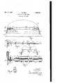
- Fig. l is a fragmentary front elevation of a motor vehicle, in which a garment hanger support of the present invention is installed, portions of the vehicle being broken away for clearness of illustration
- Y Fig. 2 is an enlarged, fragmentary top plan view partly in section, taken generally in the area indicated by the line 2-2 of Fig. l,
- Fig. 3 is a further enlarged medial sectional 'view taken on the line 3-3 of Fig. 2,
- Fig. 4 is a transverse sectional view taken on the line 4--4 of Fig. 3, and
- Fig. 5 is a fragmentary side elevation of the Y device showing the mode of mounting it on one of a pair of oppositely disposed hooks permanent ly attached to the interior of the vehicle.
- a vehicle V having a pair of windows W-W on either side of the rear portion of the passenger compartment, which windows are mounted for vertical movement as is customary in motor vehicles.
- each window mounteded on the upper edge of each window is a metal hook element I, having a lining of felt or like material 2, engaging the side surface of the window.
- the hook element I On the inner face of the window, the hook element I, has an inwardly, laterally, projecting shelf portion 3 on the upper face of which a sleeve 4 is secured by a bolt 5 extending downwardly through the sleeve, thence through the shelf portion 3, the end of the lining 2, and a washer t, and terminating in a threaded portion engaged by a nut 8.
- the bolt 5 not only secures the sleeve 4 to the upper surface of the shelf member 3, but also secures the lining element 2 to the hook element.
- the garment hanger support comprises a pair of telescoping rods 9 and I0 having iiattened ends II and I2 which ends are provided with relatively large openings as at I3 in Figs. 2 and 3, which loosely engage the upstanding post elements formed by the sleeves 4 and bolts 5 on each of the hook members I. Because of the telescoping arrangement of the tubes, when the device is installed on the Windows of the rear doors of the vehicle, either door may be opened and closed, such movement being permitted by the sliding engagement of the tubes 9 and Hl, together with the hinging action of the engagement between the flattened ends of the tubes and their respective post elements on the hook members I.
- the clearance aorded by the large opening I3 permits either window to be raised or lowered relative to the other with incident inclination of the rod assembly without such action producing a binding or cramping eect on the windows as has characterized prior art devices. Furthermore, this loose engagement assists in the installation of the device I since the hooks can first be separately applied to the vehicle windows and the rod assembly can then be assembled on to the upstanding post elements on each of the supporting hooks. Still further, because of the telescoping sliding engagement of the members 9 and I0, the device is applicable to a Wide range of vehicle widths, although for installations on vehicle windows other than door windows, the rod may be made of a single element of the correct length.
- the installation of the rod assembly is not confined to the window engaging hooks. It may be installed with equal ease on hooks I4, I4, applied to the door posts or to the roof structure of the vehicle as indicated in Fig. 5.
- the device also includes a simple means for keeping garment hangers hung on the rod assembly separated from each other for clearance of the garments, and for conning the garments to the extreme ends of the rod assembly so as not to impair the drivers view to the rear of the vehicle through the usual rear vision mirror and the rear window of the vehicle.
- the arrangements on each end of the rod assembly are similar except those on the smaller member I Il are reduced in size to accommodate the smaller rod.
- Each assembly comprises a series of resilient rubber rings I5, tightly but slideably engaging the respective rod elements 9 and I0. The outermost of these rings additionally clamp the laterally extending legs I6 and I6 of a shallow inverted U-shaped strip of metal I1 to the outer upper surface of the rod members.
- This member extends above the rod and above the intermediate ring elements I5 and operates to prevent a garment hanger G from being dislodged from the rod incident to any violent upward movement of the vehicle body such as would be produced by going overrough spots in the highway and thus, the member I1 assists in maintaining the garment hangers and the garments carried thereby in place on this supporting rod structure.
- the device is composed of few parts, and all of the parts either are such as may be purchased on the open market, or such as do not require expensive tooling for manufacture, and consequently, the device is economical to manufacture. It is simple in construction, and can be readily installed on motor vehicles and can be as readily removed as occasion may require. It is to be noted that, if desired, the rod and any garments hung thereon may be removed from, or placed in the Vehicle as a unit without releasing the supporting hooks from the windows.
- a demountable garment hanger for motor vehicles comprising a pair of telescopically interengaging tubular members combining to form a garment supporting rod; each of said tubular members at the end thereof remote from the point of interengagement being flattened and having a hole extending through said flattened end, and a.
- each of said hook elements comprising a strip of lmetal bent on itself to form a hook portion engaging the upper edge and adjacent side faces of a vehicle window and having a resilient lining engaging the edge and sides of the window; the portion of each of said hook elements engaging the inner side of the window extending below the end of the hook portion engaging the outer surface of the window and terminating in a laterally extending rod supporting ledge having an upwardly extending stud extending through the holes in said flattened ends; the thinness of said flattened end portions and the clearance between each of said studs and the associated hole in said flattened ends being suiicient to permit the unobstructed raising and lowering of either vehicle window engaged by said hooks relative to the opposite window.
- hanger positioning means comprising a pair of members located one at each end of said rod adjacent said flattened ends thereof; each of said members comprising a bar spaced from the upper surface of said rod and extending parallel thereto and having its ends secured to the surface of said rod.
Landscapes
- Engineering & Computer Science (AREA)
- Mechanical Engineering (AREA)
- Vehicle Interior And Exterior Ornaments, Soundproofing, And Insulation (AREA)
Description
Fcb. 17, 1953 v. w. BAIN 2,628,751
DEMOUNTABLE GARMENT HANGER Filed Aug. 29, 1949 INVENToR, Ver@ zu. 13am HTTOR/VEY Patented Feb. 17, 1953 y UNITED STATES PATENT OFFICE DEMOUNTABLE GARMENT HANGER Vern W. Bain, Van Nuys, Calif.
Application August 29, 1949, Serial No. 112,884
This invention relates to garment hangers and particularly to a form thereof adapted to be installed in the passenger compartment of automobiles.
An object of the present invention is to pro vide v"a garment hanger supporting means` for automobiles which may be installed either on the upper edges of the vehicle windows or upon 'supporting hooks permanently attached to the roof or sidewall structure of the vehicle.
Another object of the invention is to provide a garment hanger supporting means for motor vehicles which may be installed upon hooks mounted on the upper edge of the vehicle windows and which may be removed from the sup- 2 Claims.v (Cl. 22A- 421) porting hooks without the necessity of removing l the hooks from the windows.
'1A further object of the invention is to provide a garment hanger supporting means for motor vehicles which may be installed upon the upper edges of the windows on opposite sides of the vehicle and which is so constructed and arranged that either of the windows upon which it is mounted may be vertically adjusted to different levels if desired.
4With the above objects in view, together with such other objects and advantages as may subsequently appear, the invention resides in the parts, and in the construction, combination and arrangement of parts described in the following specification and illustrated in the accompanying drawings, which show, by way of example, one form of the invention and in which drawings:
Fig. l is a fragmentary front elevation of a motor vehicle, in which a garment hanger support of the present invention is installed, portions of the vehicle being broken away for clearness of illustration, Y Fig. 2 is an enlarged, fragmentary top plan view partly in section, taken generally in the area indicated by the line 2-2 of Fig. l,
Fig. 3 is a further enlarged medial sectional 'view taken on the line 3-3 of Fig. 2,
Fig. 4 is a transverse sectional view taken on the line 4--4 of Fig. 3, and
Fig. 5 is a fragmentary side elevation of the Y device showing the mode of mounting it on one of a pair of oppositely disposed hooks permanent ly attached to the interior of the vehicle.
Referring first to Fig. l, there is shown a vehicle V, having a pair of windows W-W on either side of the rear portion of the passenger compartment, which windows are mounted for vertical movement as is customary in motor vehicles.
Mounted on the upper edge of each window is a metal hook element I, having a lining of felt or like material 2, engaging the side surface of the window. On the inner face of the window, the hook element I, has an inwardly, laterally, projecting shelf portion 3 on the upper face of which a sleeve 4 is secured by a bolt 5 extending downwardly through the sleeve, thence through the shelf portion 3, the end of the lining 2, and a washer t, and terminating in a threaded portion engaged by a nut 8. Thus, the bolt 5 not only secures the sleeve 4 to the upper surface of the shelf member 3, but also secures the lining element 2 to the hook element.
The garment hanger support comprises a pair of telescoping rods 9 and I0 having iiattened ends II and I2 which ends are provided with relatively large openings as at I3 in Figs. 2 and 3, which loosely engage the upstanding post elements formed by the sleeves 4 and bolts 5 on each of the hook members I. Because of the telescoping arrangement of the tubes, when the device is installed on the Windows of the rear doors of the vehicle, either door may be opened and closed, such movement being permitted by the sliding engagement of the tubes 9 and Hl, together with the hinging action of the engagement between the flattened ends of the tubes and their respective post elements on the hook members I. Additionally, the clearance aorded by the large opening I3, permits either window to be raised or lowered relative to the other with incident inclination of the rod assembly without such action producing a binding or cramping eect on the windows as has characterized prior art devices. Furthermore, this loose engagement assists in the installation of the device I since the hooks can first be separately applied to the vehicle windows and the rod assembly can then be assembled on to the upstanding post elements on each of the supporting hooks. Still further, because of the telescoping sliding engagement of the members 9 and I0, the device is applicable to a Wide range of vehicle widths, although for installations on vehicle windows other than door windows, the rod may be made of a single element of the correct length.
As shown in Fig. 5, the installation of the rod assembly is not confined to the window engaging hooks. It may be installed with equal ease on hooks I4, I4, applied to the door posts or to the roof structure of the vehicle as indicated in Fig. 5.
The device also includes a simple means for keeping garment hangers hung on the rod assembly separated from each other for clearance of the garments, and for conning the garments to the extreme ends of the rod assembly so as not to impair the drivers view to the rear of the vehicle through the usual rear vision mirror and the rear window of the vehicle. The arrangements on each end of the rod assembly are similar except those on the smaller member I Il are reduced in size to accommodate the smaller rod. Each assembly comprises a series of resilient rubber rings I5, tightly but slideably engaging the respective rod elements 9 and I0. The outermost of these rings additionally clamp the laterally extending legs I6 and I6 of a shallow inverted U-shaped strip of metal I1 to the outer upper surface of the rod members. This member extends above the rod and above the intermediate ring elements I5 and operates to prevent a garment hanger G from being dislodged from the rod incident to any violent upward movement of the vehicle body such as would be produced by going overrough spots in the highway and thus, the member I1 assists in maintaining the garment hangers and the garments carried thereby in place on this supporting rod structure.
The device is composed of few parts, and all of the parts either are such as may be purchased on the open market, or such as do not require expensive tooling for manufacture, and consequently, the device is economical to manufacture. It is simple in construction, and can be readily installed on motor vehicles and can be as readily removed as occasion may require. It is to be noted that, if desired, the rod and any garments hung thereon may be removed from, or placed in the Vehicle as a unit without releasing the supporting hooks from the windows.
While I have shown and described one form of my invention, I do not intend thereby to be limited to the exact form thus disclosed, and the invention includes all such modifications of the parts, and of the construction, combination and arrangement of parts, as shall come within the purview of the appended claims.
I claim:
l. A demountable garment hanger for motor vehicles comprising a pair of telescopically interengaging tubular members combining to form a garment supporting rod; each of said tubular members at the end thereof remote from the point of interengagement being flattened and having a hole extending through said flattened end, and a. pair of hook elements demountably supporting said rod transversely of a vehicle; each of said hook elements comprising a strip of lmetal bent on itself to form a hook portion engaging the upper edge and adjacent side faces of a vehicle window and having a resilient lining engaging the edge and sides of the window; the portion of each of said hook elements engaging the inner side of the window extending below the end of the hook portion engaging the outer surface of the window and terminating in a laterally extending rod supporting ledge having an upwardly extending stud extending through the holes in said flattened ends; the thinness of said flattened end portions and the clearance between each of said studs and the associated hole in said flattened ends being suiicient to permit the unobstructed raising and lowering of either vehicle window engaged by said hooks relative to the opposite window.
2. In a demountable garment hanger as claimed in claim 1, the combination of hanger positioning means comprising a pair of members located one at each end of said rod adjacent said flattened ends thereof; each of said members comprising a bar spaced from the upper surface of said rod and extending parallel thereto and having its ends secured to the surface of said rod.
VERN W. BAIN.
REFERENCES CITED The following references are of record in the file of this patent:
UNTED STATES PATENTS Number Name Date 1,282,174 Bescher Oct. 22, 1918 1,716,708 Shipley et al. June 11, 1929 1,897,107 Baus Feb. 14, 1933 2,115,323 Wuest Apr. 25, 1938 2,334,036 Roller Nov. 9, 1943 2,344,339 Zwald Mar. 14, 1944 2,474,513 Behrens June 28, 1949 2,478,337 Strasser et al. Aug. 9, 1949 2,499,560 Bailey Mar. 7, 1950 2,522,174 Hermsmeyer Sept. 12, 1950 2,526,285 Schuyler Oct. 17, 1950 2,532,909 Hart Dec. 5, 1950 2,549,391 Secord Apr. 17, 1951 FOREIGN PATENTS Number Country Date 822,313 France Sept. 13, 1937
Priority Applications (1)
| Application Number | Priority Date | Filing Date | Title |
|---|---|---|---|
| US112884A US2628751A (en) | 1949-08-29 | 1949-08-29 | Demountable garment hanger |
Applications Claiming Priority (1)
| Application Number | Priority Date | Filing Date | Title |
|---|---|---|---|
| US112884A US2628751A (en) | 1949-08-29 | 1949-08-29 | Demountable garment hanger |
Publications (1)
| Publication Number | Publication Date |
|---|---|
| US2628751A true US2628751A (en) | 1953-02-17 |
Family
ID=22346347
Family Applications (1)
| Application Number | Title | Priority Date | Filing Date |
|---|---|---|---|
| US112884A Expired - Lifetime US2628751A (en) | 1949-08-29 | 1949-08-29 | Demountable garment hanger |
Country Status (1)
| Country | Link |
|---|---|
| US (1) | US2628751A (en) |
Cited By (7)
| Publication number | Priority date | Publication date | Assignee | Title |
|---|---|---|---|---|
| US2733846A (en) * | 1956-02-07 | Article support | ||
| US2777624A (en) * | 1954-11-01 | 1957-01-15 | Jean O Nelson | Adjustable clothes hanger |
| US2929539A (en) * | 1957-08-19 | 1960-03-22 | Douglas E Safreno | Rack for vehicle cab |
| US2945595A (en) * | 1958-01-03 | 1960-07-19 | Jr Charles Gardner | Clothes hanger |
| US2969881A (en) * | 1958-01-22 | 1961-01-31 | Patrick E Lilly | Clothes hanger rod for automobiles |
| US3481483A (en) * | 1969-04-01 | 1969-12-02 | Federated Merchandisers Inc | Automobile clothes rack |
| WO2000048865A1 (en) * | 1999-02-18 | 2000-08-24 | Holmen Dick | A device for securing one or more load units in a vehicle stowage compartment |
Citations (14)
| Publication number | Priority date | Publication date | Assignee | Title |
|---|---|---|---|---|
| US1282174A (en) * | 1918-01-04 | 1918-10-22 | Kenneth A Bescher | Hanging bracket. |
| US1716708A (en) * | 1926-04-08 | 1929-06-11 | Elmer E Shipley | Coat and hat rack |
| US1897107A (en) * | 1931-11-13 | 1933-02-14 | Bernard P Baus | Automobile table |
| FR822313A (en) * | 1936-05-27 | 1937-12-28 | Flax Kg | Towel rack |
| US2115323A (en) * | 1935-09-09 | 1938-04-26 | Nat Incar Table Co Inc | Automobile serving tray |
| US2334036A (en) * | 1942-11-21 | 1943-11-09 | Roller Robert | Multiple garment hanger |
| US2344339A (en) * | 1940-02-28 | 1944-03-14 | Zwald Nicholas | Automobile window supported hatrack and coat hanger device |
| US2474513A (en) * | 1948-01-17 | 1949-06-28 | Paul H Behrens | Bracket attachment for motor vehicle windows |
| US2478337A (en) * | 1948-08-05 | 1949-08-09 | Lena W Strasser | Garment hanger for automobiles |
| US2499560A (en) * | 1947-09-22 | 1950-03-07 | Harley R Bailey | Rod for hanging garments in automobiles |
| US2522174A (en) * | 1948-04-12 | 1950-09-12 | Melvin L Hermsmeyer | Garment hanger support for automobiles |
| US2526285A (en) * | 1949-04-02 | 1950-10-17 | John B Schuyler | Clothes supporting rack |
| US2532909A (en) * | 1946-05-13 | 1950-12-05 | Alberta M Talmadge | Wearing apparel support |
| US2549391A (en) * | 1948-07-26 | 1951-04-17 | Henry J Secord | Automobile bracket |
-
1949
- 1949-08-29 US US112884A patent/US2628751A/en not_active Expired - Lifetime
Patent Citations (14)
| Publication number | Priority date | Publication date | Assignee | Title |
|---|---|---|---|---|
| US1282174A (en) * | 1918-01-04 | 1918-10-22 | Kenneth A Bescher | Hanging bracket. |
| US1716708A (en) * | 1926-04-08 | 1929-06-11 | Elmer E Shipley | Coat and hat rack |
| US1897107A (en) * | 1931-11-13 | 1933-02-14 | Bernard P Baus | Automobile table |
| US2115323A (en) * | 1935-09-09 | 1938-04-26 | Nat Incar Table Co Inc | Automobile serving tray |
| FR822313A (en) * | 1936-05-27 | 1937-12-28 | Flax Kg | Towel rack |
| US2344339A (en) * | 1940-02-28 | 1944-03-14 | Zwald Nicholas | Automobile window supported hatrack and coat hanger device |
| US2334036A (en) * | 1942-11-21 | 1943-11-09 | Roller Robert | Multiple garment hanger |
| US2532909A (en) * | 1946-05-13 | 1950-12-05 | Alberta M Talmadge | Wearing apparel support |
| US2499560A (en) * | 1947-09-22 | 1950-03-07 | Harley R Bailey | Rod for hanging garments in automobiles |
| US2474513A (en) * | 1948-01-17 | 1949-06-28 | Paul H Behrens | Bracket attachment for motor vehicle windows |
| US2522174A (en) * | 1948-04-12 | 1950-09-12 | Melvin L Hermsmeyer | Garment hanger support for automobiles |
| US2549391A (en) * | 1948-07-26 | 1951-04-17 | Henry J Secord | Automobile bracket |
| US2478337A (en) * | 1948-08-05 | 1949-08-09 | Lena W Strasser | Garment hanger for automobiles |
| US2526285A (en) * | 1949-04-02 | 1950-10-17 | John B Schuyler | Clothes supporting rack |
Cited By (7)
| Publication number | Priority date | Publication date | Assignee | Title |
|---|---|---|---|---|
| US2733846A (en) * | 1956-02-07 | Article support | ||
| US2777624A (en) * | 1954-11-01 | 1957-01-15 | Jean O Nelson | Adjustable clothes hanger |
| US2929539A (en) * | 1957-08-19 | 1960-03-22 | Douglas E Safreno | Rack for vehicle cab |
| US2945595A (en) * | 1958-01-03 | 1960-07-19 | Jr Charles Gardner | Clothes hanger |
| US2969881A (en) * | 1958-01-22 | 1961-01-31 | Patrick E Lilly | Clothes hanger rod for automobiles |
| US3481483A (en) * | 1969-04-01 | 1969-12-02 | Federated Merchandisers Inc | Automobile clothes rack |
| WO2000048865A1 (en) * | 1999-02-18 | 2000-08-24 | Holmen Dick | A device for securing one or more load units in a vehicle stowage compartment |
Similar Documents
| Publication | Publication Date | Title |
|---|---|---|
| US1962508A (en) | Armrest | |
| US2628751A (en) | Demountable garment hanger | |
| US2594813A (en) | Automobile window sunvisor shade | |
| US3424314A (en) | Clothes bar | |
| US2461722A (en) | Hanger device for automobile windows | |
| US3053566A (en) | Screen for station wagon | |
| US2139156A (en) | Detachable screen for automobiles | |
| US2997103A (en) | Screen for motor car windows | |
| US2316640A (en) | Air conditioning unit mounting | |
| US3326594A (en) | Camping body for motor vehicles | |
| US2916763A (en) | Torsion bar hinge assembly | |
| US2093314A (en) | Window screening device | |
| US2647669A (en) | Clothes rack | |
| US1827353A (en) | Vehicle screen | |
| US1639589A (en) | Screen for automobiles | |
| US2152414A (en) | Cowl ventilator screen | |
| US1789889A (en) | Window-positioning organization | |
| US2756093A (en) | Bed compartments for the cabs of trailer trucks | |
| US2127330A (en) | Device for operating venetian blinds | |
| US1763371A (en) | Screen mounting | |
| US1741202A (en) | Automobile awning | |
| US1400567A (en) | Curtain attachment for windshields | |
| US1561391A (en) | Glare screen | |
| US1557167A (en) | Theft-indicating windshield for vehicles | |
| US2240588A (en) | Adjustable automobile screen |