US2626756A - Pressure differential control system for closed steam boiler return systems - Google Patents
Pressure differential control system for closed steam boiler return systems Download PDFInfo
- Publication number
- US2626756A US2626756A US182788A US18278850A US2626756A US 2626756 A US2626756 A US 2626756A US 182788 A US182788 A US 182788A US 18278850 A US18278850 A US 18278850A US 2626756 A US2626756 A US 2626756A
- Authority
- US
- United States
- Prior art keywords
- pressure
- steam
- condensate
- valve
- switch
- Prior art date
- Legal status (The legal status is an assumption and is not a legal conclusion. Google has not performed a legal analysis and makes no representation as to the accuracy of the status listed.)
- Expired - Lifetime
Links
- 230000007935 neutral effect Effects 0.000 description 6
- QSHDDOUJBYECFT-UHFFFAOYSA-N mercury Chemical compound [Hg] QSHDDOUJBYECFT-UHFFFAOYSA-N 0.000 description 4
- 229910052753 mercury Inorganic materials 0.000 description 4
- XLYOFNOQVPJJNP-UHFFFAOYSA-N water Substances O XLYOFNOQVPJJNP-UHFFFAOYSA-N 0.000 description 4
- 239000000446 fuel Substances 0.000 description 3
- 238000004326 stimulated echo acquisition mode for imaging Methods 0.000 description 3
- 238000013022 venting Methods 0.000 description 3
- 238000010586 diagram Methods 0.000 description 2
- 239000007789 gas Substances 0.000 description 2
- 239000002699 waste material Substances 0.000 description 2
- 238000009835 boiling Methods 0.000 description 1
- 238000010276 construction Methods 0.000 description 1
- 230000007423 decrease Effects 0.000 description 1
- 238000010438 heat treatment Methods 0.000 description 1
- 239000007788 liquid Substances 0.000 description 1
- 238000012986 modification Methods 0.000 description 1
- 230000004048 modification Effects 0.000 description 1
- 229920006395 saturated elastomer Polymers 0.000 description 1
Images

Classifications
-
- F—MECHANICAL ENGINEERING; LIGHTING; HEATING; WEAPONS; BLASTING
- F24—HEATING; RANGES; VENTILATING
- F24D—DOMESTIC- OR SPACE-HEATING SYSTEMS, e.g. CENTRAL HEATING SYSTEMS; DOMESTIC HOT-WATER SUPPLY SYSTEMS; ELEMENTS OR COMPONENTS THEREFOR
- F24D19/00—Details
- F24D19/10—Arrangement or mounting of control or safety devices
- F24D19/1003—Arrangement or mounting of control or safety devices for steam heating systems
Definitions
- This invention relates to steam utilization systems, and more particularly to an improved control system for minimizing the heat loss in a steam utilization system of the closed type.
- a main object of the invention is to provide a novel and improved system of control for minimizing the heat loss in a steam utilization system of the closed type, the improved control system involving relatively simple apparatus, providing a great increase in efficiency and economy in the utilization of fuel, and functioning to prevent heat loss in a closed steam utilization system by preventing the generation of flash steam.
- a further object of the invention is to provide an improved steam utilization system of the closed type wherein a constant and adjustable difierential pressure relationship is established between the steam lines which supply steam for utilization and the condensate return lines which carry the hot steam condensate away from the machinery or equipment in which the steam is utilized.
- a still further object of the invention is to provide an improved system of control in a steam utilization system of the closed type wherein excessive heat loss due to flash steam generation in the condensate return lines is effectively prevented, whereby maximum utilization of the heat generated in the system is provided.
- a still further object of the invention is to provide an improved system of control to establish and maintain a constant and adjustable differential pressure relationship between the steam supply lines and condensate return lines in a steam utilization system of the closed type wherein sufficiently accurate control is provided to have the steam utilizing equipment and the steam boiler at the same elevation or to allow the boiler to be located above the steam utilizing equipment, the control system of the present invention being arranged so that just enough difference in pressure between the steam supply lines and the condensate lines may be maintained to permit the condensate to flow back into the condensate receiver, from whence it may be pumped back into the boiler, regardless of the relative elevation of the boiler and the utilization equipment.
- a still further object of the invention is to provide an improved control means in a steam utilization system of the closed type wherein a substantially constant diiierence in pressure between the steam supply lines and the condensate return lines may be maintained and may be set at a value just high enough to lift the condensate 5 Claims. (Cl. 237-9) from the trap discharge points of the utilization equipment back into the condensate receiver, whereby the flash loss may be held at a minimum, thus minimizing waste of steam in the system.
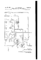
- FIG. 1 is a schematic diagram of an improved steam utilization system constructed'in accordance with the present invention
- FIG. 2 is a schematic diagram of another form of steam utilization system constructed in accordance with and employing the principles of the present invention.
- Figure 3 is a fragmentary cross sectional view taken through a conventional pressure-responsive differential switch employed in the system of Figure 1.
- H designates a steam boiler
- I2 designates the steam supply line connected to the high-pressure side of the boiler H.
- Designated at l3 are steam utilization devices which may be machines, heating devices, or the like, wherein heat is extracted from steam to perform useful functions.
- each device i3 is connected to the steam supply line I 2 by a conduit [4.
- Designated at I5 is the condensate return line, the return conduit it of each of the devices l3 being connected to the return line 15 through a steam trap l1 and a check valve l8.
- Designated at 19 is a condensate receiving tank which is connected to the condensate return line I5 by a conduit 20.
- Designated at '21 is the boiler return line, said return line connecting the bottom of the condensate receiving tank I9 to the boiler H and including a pump 22 and a check valve 23.
- the pump 22 is driven by a motor 24 which is energized from the power lines, shown at 26, through a conventional float controlled switch 21 connected to the tank 19 in the manner shown schematically in Figure 1.
- the switch 21 is well known per se and forms no part of the present invention.
- Said switch 21 is connected to the tank l9 and is arranged so that the motor 24 will become energized responsive to a rise in level of the condensate in the tank IE to a predetermined height. Therefore, the pump 22 will not become energized until sufficient condensate has collected in the tank 19 to bring the level thereof in the tank to the predetermined height for which the automatic switch 21 is set.
- a conduit 28 Connected to the top of the tank I9 is a conduit 28 provided with a T-fitting 29.
- a conduit 39 Connected to one arm of the T-fittin 29 is a conduit 39 which includes a solenoid-type vent valve 3! which is normally closed. Upon energization of the vent valve 3
- Designated at 32 is a conduit which connects the supply line I2 to the other arm of the T-fitting 29 through a normally closed solenoidtype valve 33 and a check valve 33. When valve 33 is energized and open, high pressure steam from the supply line I2 will be admitted through the check valve 3G and the conduit 23 into the condensate tank I9.
- a pressure-'responsive switch device 35 Connected between the conduit 26 and the steam supply line I2 is a pressure-'responsive switch device 35 which may be, for example, a pressure-responsive switch similar to Minneapolis-Honeywell Differential Pressuretrol Model P606A and illustrated in Fig. 3. As shown in Figure '1, one side of the pressure-responsive switch device 35 is connected by a conduit 33 to said pressure-responsive device is connected by a conduit 3! to the condensate line 20.
- the switch device 35 is provided with respective terminals 38, 39 and 40. Said switch -device may be set so that when the pressure differential between conduits 36 and 31 is substantially less than a predetermined value, the terminals 33 and 39 will be bridged.
- the switch device When thus set, the switch device will operate to bridge the terminals 39 and it when differential between conduits
- the switch device 35 When the pressure differential between conduits 36 and 3? is substantially equal to said predetermined set value, the switch device 35 will be in a neutral condition and both terminals 38 and 40 will be disconnected from terminal 39. It will therefore be apparent that when the pressure differential between the steam supply v line I2 and the condensate return line 23 is below a predetermined desired value, the terminals 33 and 39 will be bridged.
- the respective solenoid valves 3! and 33 have their energizing coils connected'to the respective sets of wires shown at 4
- is connected to one terminal of a suitable voltage source.
- the terminal 39 ofthe switch 35 is connected by a wire 44 to the other terminal of the voltage source.
- Wire 42 is connected to the terminal 38 of the switch and wire 33 is connected to terminal ii! of the switch. Therefore, when the pressure differential between conduits i 2 and 2c is below to close.
- the switch 35 functions to bridge the terminals 39 and All, energizing the valve 33 and causing said valve 33 to open, whereby the steam from the supply line i2 is admitted into the tank I9 through the conduit 32 and the conduit 28, thereby increasing the pressure in the tank I9 and reducing the pressure differential between the conduit 28 and the supply line I2.
- the switch 35 When the desired predetermined differential pressure is established between conduits 20 and I2, the switch 35 functions to open the connection between the terminals 39 and 40, thereby deenergizing the valve 33 and causing said valve to close. It will therefore be apparent that by setting the pressure-responsive switch device 35 to a predetermined setting, the pressure differential between the steam supply line I2 and the condensate return line 23 may be held and maintained at a value just sufiicient to lift the condensate from the trap discharge element I'I back into the condensate tank I9, regardless of the relative elevation of the condensate tank I9 and the devices .53. It is therefore possible to minimize the flash loss in the system, and therefore to minimize the waste of heat due to flash loss.
- the pump 22 When said low point is reached, the pump 22 is deenergized.
- the correct level in the boiler II is maintained by a separate system having no relation to the condensate return system above described, and operating separately from different control elements, and having an independent source of water.
- the present system merely returns the hot condensate to the boiler and furnishes no make-up water whatsoever.
- the boiler II is fired and starts to build up pressure in the steam supply line.
- the equipment is is full of air and is cold. As steam first enters the equipment l3, it begins to displace the air within the equipment and at the same time condenses rapidly.
- the air and condensate from the equipment pass through the steam trap I! and out .into the main return line I 5.
- the air and cold condensate flow along the return line and through the return conduit 26 into the tank i9, where the condensate begins to accumulate and the air passes out of valve 3! to the atmosphere, said valve being open, since there is no differential pressure between conduits 3i and 35. Valve ill will remain open as long as less than the predetermined value of differential pressure exists between conduits 36 and 37.
- the switch 35 moves to its neutral position, opening the connection across the terminals 39 and 49 and deenergizing the valve 33, causing said valve to close. This places the switch 35 in a neutral position and establishes a balanced condition wherein the steam from the hot condensate is balancing the demand for pressure most of the time after the system is hot.
- the pressure in the condensate return line may rise gradually to a point where the differential pressure is less than the preset value, causing the switch 35 to operate so as to open valve 3
- the switch 35 moves into neutral position and remains therein until the system again becomes unbalanced.
- the present invention operates to maintain the return system under a constant relative pressure lower than the boiler pressure only by an amount sufficient to produce flow of the condensate back to the condensate tank l9.
- the switch 35 employed in Figure 1 is of standard construction and is of the opposed pressurebellows operated type, as shown in Figure 3.
- the two bellows, designated at 38A and 40A in Figure 3 oppose each other and are spring-loaded in a manner to allow operation in one direction to close one set of mercury switch contacts when the desired and set control point is reached, and to operate in the opposite direction when the desired and set control point is not satisfied.
- will be held open by the differential switch contacts 38 and 39 until the steam pressure in the system exceeds the set control point of the spring 83, said switch being held in this position by a difference in pressure in the lines 36 and 31.
- the mercury switch tube tilts in the opposite direction in just the correct amount to open contacts 38 and 39 but not far enough as yet to close contacts 39 and All.
- closes. Valve 3
- pressure begins to build up in the return lines and in the return system.
- the condensate is still too cold to give off any flash steam at this time (start up) pressure in the return lines and return receiver will begin to fall too far below the steam supply pressure, thus unbalancing the neutral position of the differential switch by reason of the differences in forces exerted by bellows 38A and 49A and the spring 88 pulling in a direction to aid, or add to the force exerted by bellows 38A.
- l9 designates the condensate tank and i3 designates the steam utilization devices.
- Steam is provided to the utilization devices from the steam supply line l2 through the conduit it, and the condensate leaves each device it through the conduit l6, steam trap ii, the check valve it, and returns to the condensate tank through the condensate return .line 28.
- the pump 22 becomes activated by the closing of the levelresponsive switch G, whereby the accumulated condensate is returned to the boiler ll, through the line 25.
- the condensate tank l9 may be provided with a safety valve 50 which is adapted to open at a limiting high pressure.
- a vent conduit 54 provided with a normally closed solenoid valve A.
- Designated at 52 and 53 are respective electrical supply line wires.
- One terminal of the solenoid valve A is connected to line wire 53 by a wire d.
- the other terminal of the solenoid valve A is connected by a wire 55 to the line wire 52 through a pressure-responsive switch F.
- Switch F is connected between the steam supply line 12 and the condensate tank by respective conduits 5S, 5?, 58 and Eli, shown. Switch F is arranged to close when the differential pressure between conduits 53 and 5?
- valve A When valve A opens, the tank 13 is vented to atmosphere.
- the condensate tank is connected to the steam supply line l2 by the respective conduits 59, iii and as shown, a solenoid valve B being inculded in the conduit of valve B is connected to line wire 53 and the other terminal is connected by a wire iii to the line wire 52 through a pressure-responsive switch E.
- the pressure-responsive switch E is connected by respective conduits 6-2 and 63 between the conduits til 5'1, as whereby switch is controlled by the differential pressure between the steam supply line i2 and the condensate tank ill.
- the valve 13 is normally closed and the switch E is arranged to close responsive to a rise in differential pressure between conduits and 63 beyond the predetermined set value mentioned above in connection with switch F.
- switch E closes, causing the valve B to become energize-:1 and to open, and causing steam to be admitted from the supply line i2 into the condensate tank it.
- This increases the pressure in the condensate tank is and reduces the differential pressure between conduits 62 and 83, whereby when the predetermined desired differential pressure is reached, the switch E. opens and causes the valve B to close.
- a temperature-responsive switch C is provided in condensate tank it, said switch being normally closed and being connected in parallel with switch F, as shown.
- the system of Figure 2 operates as follows: Assuming the apparatus is in a cold condition, the boiler l l is fired. Valve A is held open, since the switch C is closed, allowing the tank is to be vented and allowing condensate to flow back to the tank 19 as soon as any pressure builds up in the boiler H. Since valve A is open, any air in the system is free to pass out into the atmosphere as soon as it reaches the tank it. The above condition continues until the condensate in the One terminal I condensate tank I 9 reaches a predetermined temperature, for example, a temperature of 200 F., or the like, at which time switch C opens.
- a predetermined temperature for example, a temperature of 200 F., or the like
- Valve A cannot close, however, unless difierential switch F is opened by the presence of at least the predetermined desired value of differential pressure between conduits 5! and 58. Venting through valve A would therefore continue until the differential pressure reaches the predetermined desired set condition and the temperature of the condensate in the tank i 9 is more than the above-mentioned predetermined value, for example, 260 .3.
- valve .A closes, continued increase in boiler pressure causes the pressure in the condensate tank to rise.
- the pressure in the condensate tank l3 will be maintained at the predetermined difierential pressure with respect to the boiler pressure by the action of valve B which is maintained open by pressure-responsive switch E as long as the differential pressure between conduits 62 and 63 exceeds the predetermined desired difierential pressure value.
- valve B which is maintained open by pressure-responsive switch E as long as the differential pressure between conduits 62 and 63 exceeds the predetermined desired difierential pressure value.
- the differential pressure between conduits 5S and 5? decreases below the desired value, causing the switch F to close and the valve A to open, and allowing the tank It to be vented to atmosphere.
- the operation of the system therefore is similar to the operation of the system illustrated in Figure l, inasmuch as the differential pressure between tank It and supply line !2 is maintained substantially at a constant value regardless of fluctuations of the boiler steam supplied pressure.
- vent valve A is held open when the condensate is relatively cold, since the temperature-responsive switch C is closed.
- the switch C When the condensate in tank l9 rises above the above-mentioned predetermined high temperature, the switch C is open and the valve A will close unless the differential pressure between the steam supply line and the condensate tank is less than the predetermined desired value, since this will cause the switch F to close.
- the difierential pressure is at its desired value and the condensate in the tank I9 'is above the predetermined limiting temperature above defined, both switches F and C will be open and the valve A will be deenergized and in closed condition.
- a steam utilization system comprising a boiler, a steam utilization device, a condensate collecting chamber, conduit means connecting said boiler, utilization device and chamber to define a closed system, a vent valve connected to said chamber, additional conduit means connecting the high pressure side of the boiler to said chamber, a second valve in said additional conduit means, and a pressure responsive device connected across said utilization device and arranged to selectively control said valves in accordance with variations of the difference in pressure across said utilization device and being further arranged to maintain a substantially constant difierence in pressure.
- a steam utilization system comprising a boiler, a steam utilization device, a condensate collecting chamber, conduit means connecting said boiler, utilization device and chamber to define a closed system, a normally closed vent valve connected to said chamber, additional conduit means connecting the high pressure side of the boiler to said chamber, a second normally closed valve in said additional conduit means, and a pressure responsive device connected across said utilization device and arranged to open said vent valve when the pressure differential across said pressure responsive device is substantially below a predetermined value, the pressure in the condensate collecting chamber being substantially above atmospheric pressure, said pressure responsive device being further arranged to open said second valve when said pressure differential is substantially above said predetermined value.
- a steam utilization system comprising a boiler, a steam utilization device, a condensate collecting chamber, conduit means connecting said boiler, utilization device and chamber to define a closed system, a normally closed electromagnetic vent valve connected to said chamber, additional conduit means connecting the high pressure side of the boiler to said chamber, a second normally closed electromagnetic valve in said additional conduit means, and a pressure responsive switch connected across said utilization device and arranged to selectively control said valves in accordance with variations of the difference in pressure across said utilization device, and being further arranged to maintain a substantially constant difference in pressure.
- a steam utilization system comprising a boiler, a steam utilization device, a condensate collecting chamber, conduit means connecting said boiler, utilization device and chamber to define a closed system, a normally closed electromagnetic vent valve connected to said chamber, additional conduit means connecting the high pressure side of the boiler to said chamber, a second normally closed electromagnetic valve in said additional conduit means, a pressure-responsive switch connected across said utilization device, and respective circuit means connecting said switch to said valves, said switch and circuit means being arranged to energize the vent valve when the pressure differential across said switch is substantially below a predetermined value and to energize said second valve when said pressure difizerential is substantially above said predetermined value, the pressure in the condensate collecting chamber being substantially above atmospheric pressure.
- a steam utilization system comprising a steam boiler, a steam utilization device, a condensate chamber, conduit means connecting said boiler, utilization device and chamber in a closed system, a normally closed vent valve connected to said chamber, a branch conduit connected between the high pressure side of said boiler and said chamber, a second normally closed valve in said branch conduit, and pressure-responsive means connected between said chamber and said high pressure side of the boiler and arranged to open said vent valve when the pressure differential between the chamber and the high pressure side of the boiler is substantially less than a predetermined value, and to open said second valve and close the vent valve when said differential exceeds said predetermined value, the pres. sure in the condensate chamber being substantially above atmospheric pressure.
Landscapes
- Engineering & Computer Science (AREA)
- Physics & Mathematics (AREA)
- Thermal Sciences (AREA)
- Chemical & Material Sciences (AREA)
- Combustion & Propulsion (AREA)
- Mechanical Engineering (AREA)
- General Engineering & Computer Science (AREA)
- Control Of Steam Boilers And Waste-Gas Boilers (AREA)
Description
1953 A G. ARBOGAST 2,6 ,7
PRESSURE DIFFERENTIAL. CONTROL SYSTEM FOR CLOSED STEAM BOILER RETURN SYSTEMS Filed Sept. 1, 1950 2 SHEETSSHEIET l INVENTOR. A4 r4 aflkaaawsr BY WM, v gm P v w R. 4 mm 2 m a w m m o R 6 V 6 a Q mm mm m s lll .m RWWQW *4 WW FHSR. QESRQRSV 6 w w xwSuwwE M 2 L A fl T @U W m w w B R A A. G. PRESSURE DIFFERENTIAL CONTROL. SYSTEM FOR CLOSED STEAM BOILER RETURN SYSTEMS Jan. 27, 1953 Filed Sept. 1, 1950 Patented Jan. 27, 1953 PRESSURE DIFFERENTIAL CONTROL SYS- TEM FOR CLOSED STEAM BOILER RE- TURN SYSTEMS Alva G. Arbogast, Charleston, W. Va.
Application September 1, 1950, Serial No. 182,788
This invention relates to steam utilization systems, and more particularly to an improved control system for minimizing the heat loss in a steam utilization system of the closed type.
A main object of the invention is to provide a novel and improved system of control for minimizing the heat loss in a steam utilization system of the closed type, the improved control system involving relatively simple apparatus, providing a great increase in efficiency and economy in the utilization of fuel, and functioning to prevent heat loss in a closed steam utilization system by preventing the generation of flash steam.
A further object of the invention is to provide an improved steam utilization system of the closed type wherein a constant and adjustable difierential pressure relationship is established between the steam lines which supply steam for utilization and the condensate return lines which carry the hot steam condensate away from the machinery or equipment in which the steam is utilized.
A still further object of the invention is to provide an improved system of control in a steam utilization system of the closed type wherein excessive heat loss due to flash steam generation in the condensate return lines is effectively prevented, whereby maximum utilization of the heat generated in the system is provided.
A still further object of the invention is to provide an improved system of control to establish and maintain a constant and adjustable differential pressure relationship between the steam supply lines and condensate return lines in a steam utilization system of the closed type wherein sufficiently accurate control is provided to have the steam utilizing equipment and the steam boiler at the same elevation or to allow the boiler to be located above the steam utilizing equipment, the control system of the present invention being arranged so that just enough difference in pressure between the steam supply lines and the condensate lines may be maintained to permit the condensate to flow back into the condensate receiver, from whence it may be pumped back into the boiler, regardless of the relative elevation of the boiler and the utilization equipment.
A still further object of the invention is to provide an improved control means in a steam utilization system of the closed type wherein a substantially constant diiierence in pressure between the steam supply lines and the condensate return lines may be maintained and may be set at a value just high enough to lift the condensate 5 Claims. (Cl. 237-9) from the trap discharge points of the utilization equipment back into the condensate receiver, whereby the flash loss may be held at a minimum, thus minimizing waste of steam in the system.
Further objects and advantages of the invention will become apparent from the following description and claims, and from the accompanying drawings, wherein:
Figure 1 is a schematic diagram of an improved steam utilization system constructed'in accordance with the present invention;
Figure 2 is a schematic diagram of another form of steam utilization system constructed in accordance with and employing the principles of the present invention;
Figure 3 is a fragmentary cross sectional view taken through a conventional pressure-responsive differential switch employed in the system of Figure 1.
Referring to the drawings, and more particularly to Figure 1, H designates a steam boiler, and I2 designates the steam supply line connected to the high-pressure side of the boiler H. Designated at l3 are steam utilization devices which may be machines, heating devices, or the like, wherein heat is extracted from steam to perform useful functions. As shown in Figure 1, each device i3 is connected to the steam supply line I 2 by a conduit [4. Designated at I5 is the condensate return line, the return conduit it of each of the devices l3 being connected to the return line 15 through a steam trap l1 and a check valve l8. Designated at 19 is a condensate receiving tank which is connected to the condensate return line I5 by a conduit 20. Designated at '21 is the boiler return line, said return line connecting the bottom of the condensate receiving tank I9 to the boiler H and including a pump 22 and a check valve 23. The pump 22 is driven by a motor 24 which is energized from the power lines, shown at 26, through a conventional float controlled switch 21 connected to the tank 19 in the manner shown schematically in Figure 1. The switch 21 is well known per se and forms no part of the present invention. Said switch 21 is connected to the tank l9 and is arranged so that the motor 24 will become energized responsive to a rise in level of the condensate in the tank IE to a predetermined height. Therefore, the pump 22 will not become energized until sufficient condensate has collected in the tank 19 to bring the level thereof in the tank to the predetermined height for which the automatic switch 21 is set.
the pressure 36 and 31 exceeds said predetermined value.
Connected to the top of the tank I9 is a conduit 28 provided with a T-fitting 29. Connected to one arm of the T-fittin 29 is a conduit 39 which includes a solenoid-type vent valve 3! which is normally closed. Upon energization of the vent valve 3|, said valve opens and allows the conduit 28 to be in communication with the atmosphere. Designated at 32 is a conduit which connects the supply line I2 to the other arm of the T-fitting 29 through a normally closed solenoidtype valve 33 and a check valve 33. When valve 33 is energized and open, high pressure steam from the supply line I2 will be admitted through the check valve 3G and the conduit 23 into the condensate tank I9.
Connected between the conduit 26 and the steam supply line I2 is a pressure-'responsive switch device 35 which may be, for example, a pressure-responsive switch similar to Minneapolis-Honeywell Differential Pressuretrol Model P606A and illustrated in Fig. 3. As shown in Figure '1, one side of the pressure-responsive switch device 35 is connected by a conduit 33 to said pressure-responsive device is connected by a conduit 3! to the condensate line 20. The switch device 35 is provided with respective terminals 38, 39 and 40. Said switch -device may be set so that when the pressure differential between conduits 36 and 31 is substantially less than a predetermined value, the terminals 33 and 39 will be bridged. When thus set, the switch device will operate to bridge the terminals 39 and it when differential between conduits When the pressure differential between conduits 36 and 3? is substantially equal to said predetermined set value, the switch device 35 will be in a neutral condition and both terminals 38 and 40 will be disconnected from terminal 39. It will therefore be apparent that when the pressure differential between the steam supply v line I2 and the condensate return line 23 is below a predetermined desired value, the terminals 33 and 39 will be bridged. The respective solenoid valves 3! and 33 have their energizing coils connected'to the respective sets of wires shown at 4|, 42 and ll, 43. The wire 4| is connected to one terminal of a suitable voltage source. The terminal 39 ofthe switch 35 is connected by a wire 44 to the other terminal of the voltage source. Wire 42 is connected to the terminal 38 of the switch and wire 33 is connected to terminal ii! of the switch. Therefore, when the pressure differential between conduits i 2 and 2c is below to close. Similarly, when the pressure difierential across conduits I2 and 2t exceeds the predetermined set value, the switch 35 functions to bridge the terminals 39 and All, energizing the valve 33 and causing said valve 33 to open, whereby the steam from the supply line i2 is admitted into the tank I9 through the conduit 32 and the conduit 28, thereby increasing the pressure in the tank I9 and reducing the pressure differential between the conduit 28 and the supply line I2. When the desired predetermined differential pressure is established between conduits 20 and I2, the switch 35 functions to open the connection between the terminals 39 and 40, thereby deenergizing the valve 33 and causing said valve to close. It will therefore be apparent that by setting the pressure-responsive switch device 35 to a predetermined setting, the pressure differential between the steam supply line I2 and the condensate return line 23 may be held and maintained at a value just sufiicient to lift the condensate from the trap discharge element I'I back into the condensate tank I9, regardless of the relative elevation of the condensate tank I9 and the devices .53. It is therefore possible to minimize the flash loss in the system, and therefore to minimize the waste of heat due to flash loss.
In operation of the system of Figure l, steam from the boiler ii flows to the steam heated equipment through the supply line I2 and the conduits I4. As heat is drawn from the devices 53, condensate forms in the devices and is released by conventional steam traps I? into the return line I5, whence the condensate flows through the condensate return conduit 20 into the condensate tank I 9. The condensate accumulates in the tank [8 until it reaches a predetermined level, at which time the float-operated switch 21 closes and starts the motor 24 connected to the pump 22. The pump 22 returns the condensate through the conduit 2| to the boiler and continues in operation until the liquid level in the condensate tank I9 drops to a predetermined low point. When said low point is reached, the pump 22 is deenergized. As will be understood by those skilled in the art, the correct level in the boiler II is maintained by a separate system having no relation to the condensate return system above described, and operating separately from different control elements, and having an independent source of water. The present system merely returns the hot condensate to the boiler and furnishes no make-up water whatsoever.
The following is a description of a typical starting operation of the system of Figure l:
The boiler II is fired and starts to build up pressure in the steam supply line. The equipment is is full of air and is cold. As steam first enters the equipment l3, it begins to displace the air within the equipment and at the same time condenses rapidly. The air and condensate from the equipment pass through the steam trap I! and out .into the main return line I 5. The air and cold condensate flow along the return line and through the return conduit 26 into the tank i9, where the condensate begins to accumulate and the air passes out of valve 3! to the atmosphere, said valve being open, since there is no differential pressure between conduits 3i and 35. Valve ill will remain open as long as less than the predetermined value of differential pressure exists between conduits 36 and 37. The venting of the condensate tank I9 continues until the boiler steam pressure builds up sufliciently so that the limiting differential pressure between conduits 35 and 31 is reached. At this time, the valve 3! becomes deenergized and closes. During the time previous to the closing of valve 3i, all air has been removed from the equipment I3 and the return lines, and the condensate is entering the tank I9 in a hot condition. As the boiler continues to build up pressure, the pressure in the condensate return system rises along with it, but always remains a predetermined difference below the boiler supply pressure.
The above paragraph explains how air is purged from the system when starting from a cold, nopressure condition to establish the desired differential pressure. From the point where said differential pressure is established, one of two different conditions may occur:
1. The condensate may not come up to full working temperature, under which circumstances the pressure in the return line would lag behind the rise in boiler pressure. The differential pressure control switch 35 would sense this condition, because the differential pressure tends to increase beyond the predetermined differentialpressure setting. The increase in difierential pressure beyond the predetermined set value causes the switch 35 to bridge the terminals 39 and 4B. This opens valve 33 and causes steam to be admitted into the condensate tank |9 from conduit 32 through conduit 28. This action would continue until the pressure in the tank I9 has risen sufiiciently to re-establish the predetermined pressure differential between conduits 31 and 35. When the desired predetermined pressure differential has been re-established, the switch 35 moves to its neutral position, opening the connection across the terminals 39 and 49 and deenergizing the valve 33, causing said valve to close. This places the switch 35 in a neutral position and establishes a balanced condition wherein the steam from the hot condensate is balancing the demand for pressure most of the time after the system is hot.
2. After the system has been started and the desired differential pressure has been reached, if the condensate is up to full saturated temperature, the following operation may occur: The pressure in the condensate return line may rise gradually to a point where the differential pressure is less than the preset value, causing the switch 35 to operate so as to open valve 3| and cause steam to be vented from the condensate tank I9 until the desired differential pressure is established. As soon as the desired differential pressure is established, the switch 35 moves into neutral position and remains therein until the system again becomes unbalanced.
It will therefore be apparent that the system above described will operate to maintain the return system to the condensate tank I9 at any desired setting below that of the steam supply pressure. The desired differential will remain substantially constant as the steam supply pressure fluctuates over any range greater than the differential pressure setting. The present system above described not only saves fuel by minimizing flash loss, but increases the capacity of the boiler by returning the condensate thereto at a few degrees below the boiler water boiling point, thus relieving the boiler of the necessity of raising the water to this temperature.
If the condensate tank l9 and the return lines 20 and were not maintained at relatively high pressures, there would be an excessive loss of heat due to steam condensate giving up flash steam as the condensate is released across and through the steam traps into the condensate return line. The present invention operates to maintain the return system under a constant relative pressure lower than the boiler pressure only by an amount sufficient to produce flow of the condensate back to the condensate tank l9. By keeping the differential pressure as low as possible, name- 13, just low enough to provide proper condensate drainage, flash loss is kept down to a minimum value, thereby providing maximum fuel economy.
The switch 35 employed in Figure 1 is of standard construction and is of the opposed pressurebellows operated type, as shown in Figure 3. The two bellows, designated at 38A and 40A in Figure 3, oppose each other and are spring-loaded in a manner to allow operation in one direction to close one set of mercury switch contacts when the desired and set control point is reached, and to operate in the opposite direction when the desired and set control point is not satisfied.
To illustrate the operation of the switch 35, let us assume that the steam boiler is cold and no pressure exists in the entire steam and. condensate system. The electrical power is turned on with the circuit arranged as shown in Figure 1. The spring 88 in the differential pressure switch exerts a pulling force on the bellows linkage and initially causes the contacts 38 and 39 to be closed, thus energizing valve 3|, which is thereby opened. As mentioned above, no pressure exists in the system upon starting thereof, and at this point the steam generator is fired up to supply steam to the apparatus connected thereto. As soon as the steam generator begins to build up pressure in the system, all air and gases that are in the system start to escape through the valve 3| into the atmosphere, thus clearing the steam lines and steam heated apparatus of all air and gases, permitting live steam to fill the lines and apparatus. Valve 3| will be held open by the differential switch contacts 38 and 39 until the steam pressure in the system exceeds the set control point of the spring 83, said switch being held in this position by a difference in pressure in the lines 36 and 31. As soon as the steam pressure in the line 36 exceeds the spring loading on bellows 49A plus the steam pressure in bellows 38A, the mercury switch tube tilts in the opposite direction in just the correct amount to open contacts 38 and 39 but not far enough as yet to close contacts 39 and All. As soon as the mercury switch opens contacts 38 and 39, valve 3| closes. Valve 3| now being closed, no further venting is possible. As the steam traps operate to discharge condensate into the condensate return lines, pressure begins to build up in the return lines and in the return system. In the event the condensate is still too cold to give off any flash steam at this time (start up) pressure in the return lines and return receiver will begin to fall too far below the steam supply pressure, thus unbalancing the neutral position of the differential switch by reason of the differences in forces exerted by bellows 38A and 49A and the spring 88 pulling in a direction to aid, or add to the force exerted by bellows 38A. Bellows 39A now exerts enough force on the linkage to overcome the sum of the forces produced by bellows 38A and spring 88, thus moving the linkage far enough to close contacts 39 and 4!]. Contacts 39 and 49, now being closed, cause valve 33 to open. Valve 33, now being open, steam from the steam supply line is admitted to the return receiver until the pressure within the return lines and receiver rises to a pressure below the steam pressure in conduit 36 by the exact differential desired between the steam pressure in conduit 35 and the return pressure. At this time the forces exerted by bellows 33A and the adjustable tension spring 88 overcome the force exerted by bellows 49A, thus returning the mercury switch to its neutral position and thus opening contacts 39 and 40. Contacts 39 and 40, now being opened, the valve 33 closes and the desired differential pressure rela- '2 tionship is once again established between the input steam pressure on the equipment and the steam pressure .in the return lines and return receiver.
Referring now to the embodiment of the invention shown in Figure 2, as in Figurel, l9 designates the condensate tank and i3 designates the steam utilization devices. Steam is provided to the utilization devices from the steam supply line l2 through the conduit it, and the condensate leaves each device it through the conduit l6, steam trap ii, the check valve it, and returns to the condensate tank through the condensate return .line 28. When the level in the condensate tank reaches a predetermined value, the pump 22 becomes activated by the closing of the levelresponsive switch G, whereby the accumulated condensate is returned to the boiler ll, through the line 25. As shown in Figure 2, the condensate tank l9 may be provided with a safety valve 50 which is adapted to open at a limiting high pressure. Connected to the top of the tank It is a vent conduit 54 provided with a normally closed solenoid valve A. Designated at 52 and 53 are respective electrical supply line wires. One terminal of the solenoid valve A is connected to line wire 53 by a wire d. The other terminal of the solenoid valve A is connected by a wire 55 to the line wire 52 through a pressure-responsive switch F. Switch F is connected between the steam supply line 12 and the condensate tank by respective conduits 5S, 5?, 58 and Eli, shown. Switch F is arranged to close when the differential pressure between conduits 53 and 5? is substantially below a predetermined lirnitin value. When valve A opens, the tank 13 is vented to atmosphere. The condensate tank is connected to the steam supply line l2 by the respective conduits 59, iii and as shown, a solenoid valve B being inculded in the conduit of valve B is connected to line wire 53 and the other terminal is connected by a wire iii to the line wire 52 through a pressure-responsive switch E. The pressure-responsive switch E is connected by respective conduits 6-2 and 63 between the conduits til 5'1, as whereby switch is controlled by the differential pressure between the steam supply line i2 and the condensate tank ill. The valve 13 is normally closed and the switch E is arranged to close responsive to a rise in differential pressure between conduits and 63 beyond the predetermined set value mentioned above in connection with switch F. When the predetermined differential pressure value is exceeded, switch E closes, causing the valve B to become energize-:1 and to open, and causing steam to be admitted from the supply line i2 into the condensate tank it. This increases the pressure in the condensate tank is and reduces the differential pressure between conduits 62 and 83, whereby when the predetermined desired differential pressure is reached, the switch E. opens and causes the valve B to close. A temperature-responsive switch C is provided in condensate tank it, said switch being normally closed and being connected in parallel with switch F, as shown.
The system of Figure 2 operates as follows: Assuming the apparatus is in a cold condition, the boiler l l is fired. Valve A is held open, since the switch C is closed, allowing the tank is to be vented and allowing condensate to flow back to the tank 19 as soon as any pressure builds up in the boiler H. Since valve A is open, any air in the system is free to pass out into the atmosphere as soon as it reaches the tank it. The above condition continues until the condensate in the One terminal I condensate tank I 9 reaches a predetermined temperature, for example, a temperature of 200 F., or the like, at which time switch C opens. Valve A cannot close, however, unless difierential switch F is opened by the presence of at least the predetermined desired value of differential pressure between conduits 5! and 58. Venting through valve A would therefore continue until the differential pressure reaches the predetermined desired set condition and the temperature of the condensate in the tank i 9 is more than the above-mentioned predetermined value, for example, 260 .3. When valve .A closes, continued increase in boiler pressure causes the pressure in the condensate tank to rise. The pressure in the condensate tank l3 will be maintained at the predetermined difierential pressure with respect to the boiler pressure by the action of valve B which is maintained open by pressure-responsive switch E as long as the differential pressure between conduits 62 and 63 exceeds the predetermined desired difierential pressure value. When the pressure in tank it! rises to too high a value, the differential pressure between conduits 5S and 5? decreases below the desired value, causing the switch F to close and the valve A to open, and allowing the tank It to be vented to atmosphere. The operation of the system therefore is similar to the operation of the system illustrated in Figure l, inasmuch as the differential pressure between tank It and supply line !2 is maintained substantially at a constant value regardless of fluctuations of the boiler steam supplied pressure.
It will be noted that the vent valve A is held open when the condensate is relatively cold, since the temperature-responsive switch C is closed. When the condensate in tank l9 rises above the above-mentioned predetermined high temperature, the switch C is open and the valve A will close unless the differential pressure between the steam supply line and the condensate tank is less than the predetermined desired value, since this will cause the switch F to close. When the difierential pressure is at its desired value and the condensate in the tank I9 'is above the predetermined limiting temperature above defined, both switches F and C will be open and the valve A will be deenergized and in closed condition.
While certain specific embodiments of improved steam utilization systems of the closed type have been disclosed in the foregoing description, it will be understood that various modifications within the spirit of the invention may occur to those skilled in the art. Therefore, it is intended that no limitations be placed on the invention except as defined by the scope of the appended claims.
What is claimed is:
1. A steam utilization system comprising a boiler, a steam utilization device, a condensate collecting chamber, conduit means connecting said boiler, utilization device and chamber to define a closed system, a vent valve connected to said chamber, additional conduit means connecting the high pressure side of the boiler to said chamber, a second valve in said additional conduit means, and a pressure responsive device connected across said utilization device and arranged to selectively control said valves in accordance with variations of the difference in pressure across said utilization device and being further arranged to maintain a substantially constant difierence in pressure.
2. A steam utilization system comprising a boiler, a steam utilization device, a condensate collecting chamber, conduit means connecting said boiler, utilization device and chamber to define a closed system, a normally closed vent valve connected to said chamber, additional conduit means connecting the high pressure side of the boiler to said chamber, a second normally closed valve in said additional conduit means, and a pressure responsive device connected across said utilization device and arranged to open said vent valve when the pressure differential across said pressure responsive device is substantially below a predetermined value, the pressure in the condensate collecting chamber being substantially above atmospheric pressure, said pressure responsive device being further arranged to open said second valve when said pressure differential is substantially above said predetermined value.
3. A steam utilization system comprising a boiler, a steam utilization device, a condensate collecting chamber, conduit means connecting said boiler, utilization device and chamber to define a closed system, a normally closed electromagnetic vent valve connected to said chamber, additional conduit means connecting the high pressure side of the boiler to said chamber, a second normally closed electromagnetic valve in said additional conduit means, and a pressure responsive switch connected across said utilization device and arranged to selectively control said valves in accordance with variations of the difference in pressure across said utilization device, and being further arranged to maintain a substantially constant difference in pressure.
4. A steam utilization system comprising a boiler, a steam utilization device, a condensate collecting chamber, conduit means connecting said boiler, utilization device and chamber to define a closed system, a normally closed electromagnetic vent valve connected to said chamber, additional conduit means connecting the high pressure side of the boiler to said chamber, a second normally closed electromagnetic valve in said additional conduit means, a pressure-responsive switch connected across said utilization device, and respective circuit means connecting said switch to said valves, said switch and circuit means being arranged to energize the vent valve when the pressure differential across said switch is substantially below a predetermined value and to energize said second valve when said pressure difizerential is substantially above said predetermined value, the pressure in the condensate collecting chamber being substantially above atmospheric pressure.
5. A steam utilization system comprising a steam boiler, a steam utilization device, a condensate chamber, conduit means connecting said boiler, utilization device and chamber in a closed system, a normally closed vent valve connected to said chamber, a branch conduit connected between the high pressure side of said boiler and said chamber, a second normally closed valve in said branch conduit, and pressure-responsive means connected between said chamber and said high pressure side of the boiler and arranged to open said vent valve when the pressure differential between the chamber and the high pressure side of the boiler is substantially less than a predetermined value, and to open said second valve and close the vent valve when said differential exceeds said predetermined value, the pres. sure in the condensate chamber being substantially above atmospheric pressure.
ALVA G. ARBOGAS'I.
REFERENCES CITED The following references are of record in the file of this patent:
UNITED STATES PATENTS Number Name Date 1,999,040 Dunham Apr. 23, 1935 2,065,704 Jennings Dec. 29, 1936
Priority Applications (1)
| Application Number | Priority Date | Filing Date | Title |
|---|---|---|---|
| US182788A US2626756A (en) | 1950-09-01 | 1950-09-01 | Pressure differential control system for closed steam boiler return systems |
Applications Claiming Priority (1)
| Application Number | Priority Date | Filing Date | Title |
|---|---|---|---|
| US182788A US2626756A (en) | 1950-09-01 | 1950-09-01 | Pressure differential control system for closed steam boiler return systems |
Publications (1)
| Publication Number | Publication Date |
|---|---|
| US2626756A true US2626756A (en) | 1953-01-27 |
Family
ID=22670037
Family Applications (1)
| Application Number | Title | Priority Date | Filing Date |
|---|---|---|---|
| US182788A Expired - Lifetime US2626756A (en) | 1950-09-01 | 1950-09-01 | Pressure differential control system for closed steam boiler return systems |
Country Status (1)
| Country | Link |
|---|---|
| US (1) | US2626756A (en) |
Cited By (4)
| Publication number | Priority date | Publication date | Assignee | Title |
|---|---|---|---|---|
| US2719007A (en) * | 1952-11-07 | 1955-09-27 | Alva G Arbogast | Steam utilization system |
| US3371865A (en) * | 1966-05-20 | 1968-03-05 | Ritter Pfaudler Corp | Deaerating apparatus |
| US20090134233A1 (en) * | 2007-11-27 | 2009-05-28 | Bernard Flynn | Steam Control System |
| US20100072293A1 (en) * | 2007-11-27 | 2010-03-25 | Bernard Flynn | Steam control system |
Citations (2)
| Publication number | Priority date | Publication date | Assignee | Title |
|---|---|---|---|---|
| US1999040A (en) * | 1928-01-14 | 1935-04-23 | C A Dunham Co | Heating system |
| US2065704A (en) * | 1930-09-15 | 1936-12-29 | Irving C Jennings | Vacuum steam heating apparatus |
-
1950
- 1950-09-01 US US182788A patent/US2626756A/en not_active Expired - Lifetime
Patent Citations (2)
| Publication number | Priority date | Publication date | Assignee | Title |
|---|---|---|---|---|
| US1999040A (en) * | 1928-01-14 | 1935-04-23 | C A Dunham Co | Heating system |
| US2065704A (en) * | 1930-09-15 | 1936-12-29 | Irving C Jennings | Vacuum steam heating apparatus |
Cited By (4)
| Publication number | Priority date | Publication date | Assignee | Title |
|---|---|---|---|---|
| US2719007A (en) * | 1952-11-07 | 1955-09-27 | Alva G Arbogast | Steam utilization system |
| US3371865A (en) * | 1966-05-20 | 1968-03-05 | Ritter Pfaudler Corp | Deaerating apparatus |
| US20090134233A1 (en) * | 2007-11-27 | 2009-05-28 | Bernard Flynn | Steam Control System |
| US20100072293A1 (en) * | 2007-11-27 | 2010-03-25 | Bernard Flynn | Steam control system |
Similar Documents
| Publication | Publication Date | Title |
|---|---|---|
| US2626756A (en) | Pressure differential control system for closed steam boiler return systems | |
| US3487656A (en) | Refrigeration system with refrigerant return means | |
| US2719007A (en) | Steam utilization system | |
| US2003585A (en) | Method and apparatus for heating with steam | |
| US2819701A (en) | Boiler feed pump control | |
| US1986391A (en) | Vacuum heating system | |
| US1273577A (en) | Safety construction for refrigerant and other fluid circulating apparatus. | |
| US2224929A (en) | Air venting apparatus | |
| US2840052A (en) | Control means to prevent flashing of emergency feedwater delivered to boiler feed pumps in a closed type feedwater system | |
| US3724231A (en) | Single stage dry cylinder compressor having automatic oil drain from suction chamber to crankcase | |
| US1951588A (en) | Heating system | |
| US3797265A (en) | Pressurized refrigerant feed with recirculation | |
| US2193160A (en) | Heating system | |
| US2027880A (en) | Method of supplying steam to the radiators of steam heating systems | |
| US2208947A (en) | Control system for refrigerating apparatus | |
| US2108601A (en) | Steam heating | |
| US1828302A (en) | Vacuum heating system | |
| US2852196A (en) | Water heater | |
| US1977304A (en) | Steam heating apparatus | |
| US1945204A (en) | Boiler feed system | |
| US3429371A (en) | Surface condenser | |
| US2186680A (en) | Vacuum heating system | |
| US1972571A (en) | Distribution of heat energy | |
| US2192200A (en) | Flow control and metering device | |
| US3744511A (en) | Condensate handling system |