US2624783A - Apparatus and method for measuring magnetic flux - Google Patents
Apparatus and method for measuring magnetic flux Download PDFInfo
- Publication number
- US2624783A US2624783A US597475A US59747545A US2624783A US 2624783 A US2624783 A US 2624783A US 597475 A US597475 A US 597475A US 59747545 A US59747545 A US 59747545A US 2624783 A US2624783 A US 2624783A
- Authority
- US
- United States
- Prior art keywords
- magnetic
- coils
- coil
- magnetic field
- shaft
- Prior art date
- Legal status (The legal status is an assumption and is not a legal conclusion. Google has not performed a legal analysis and makes no representation as to the accuracy of the status listed.)
- Expired - Lifetime
Links
- 230000004907 flux Effects 0.000 title description 22
- 238000000034 method Methods 0.000 title description 14
- 238000004804 winding Methods 0.000 description 46
- 239000000696 magnetic material Substances 0.000 description 6
- 238000005259 measurement Methods 0.000 description 5
- 238000012360 testing method Methods 0.000 description 5
- 230000004048 modification Effects 0.000 description 4
- 238000012986 modification Methods 0.000 description 4
- XEEYBQQBJWHFJM-UHFFFAOYSA-N Iron Chemical compound [Fe] XEEYBQQBJWHFJM-UHFFFAOYSA-N 0.000 description 3
- 239000004020 conductor Substances 0.000 description 3
- 229920001342 Bakelite® Polymers 0.000 description 2
- 229910001209 Low-carbon steel Inorganic materials 0.000 description 2
- 229920005479 Lucite® Polymers 0.000 description 2
- 239000004637 bakelite Substances 0.000 description 2
- 230000008901 benefit Effects 0.000 description 2
- 238000010276 construction Methods 0.000 description 2
- 239000011810 insulating material Substances 0.000 description 2
- 239000004926 polymethyl methacrylate Substances 0.000 description 2
- 239000007787 solid Substances 0.000 description 2
- 241000702021 Aridarum minimum Species 0.000 description 1
- 235000010627 Phaseolus vulgaris Nutrition 0.000 description 1
- 244000046052 Phaseolus vulgaris Species 0.000 description 1
- 229910000828 alnico Inorganic materials 0.000 description 1
- 230000005540 biological transmission Effects 0.000 description 1
- 229920001971 elastomer Polymers 0.000 description 1
- -1 for example Substances 0.000 description 1
- 230000001939 inductive effect Effects 0.000 description 1
- 229910052742 iron Inorganic materials 0.000 description 1
- 239000000463 material Substances 0.000 description 1
- 239000002184 metal Substances 0.000 description 1
- 229910052751 metal Inorganic materials 0.000 description 1
- 230000002093 peripheral effect Effects 0.000 description 1
- 238000000926 separation method Methods 0.000 description 1
Images

Classifications
-
- G—PHYSICS
- G01—MEASURING; TESTING
- G01R—MEASURING ELECTRIC VARIABLES; MEASURING MAGNETIC VARIABLES
- G01R33/00—Arrangements or instruments for measuring magnetic variables
- G01R33/02—Measuring direction or magnitude of magnetic fields or magnetic flux
- G01R33/028—Electrodynamic magnetometers
- G01R33/0283—Electrodynamic magnetometers in which a current or voltage is generated due to relative movement of conductor and magnetic field
Definitions
- the present invention relates to an, apparatus and method for measuring the flux density of a magnetic field.
- An object of the present invention is to provide a novel method and apparatus for measuring magnetic. flux density devoid of the abovementioned disadvantages.
- a more specific object of the present invention is to provide a novel apparatus for measuring magnetic Ilux which is devoid of sliding electrical contacts and which employs a null methodof comparison whereby a voltage generated byrotating a coil in a magnetic field of known. flux density is bucked against the voltage generated Aby another coil rotating ina field whose ilux densityis to be measured.
- a further object of the present invention to provide apparatus for measuring magnetic field flux to a high degree of accuracy which apparatus is relatively simple, rugged, and easy tooperate.
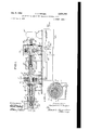
- Fig. l is a cross-sectional View of apparatusv embodying the principles of the present invention, wherein the electrical circuit portion thereof is illustrated schematically;
- Fig. 2 is a cross-sectional view of the apparatus of Fig. 1 taken along line 2-2 thereof;
- Fig. 3 is a schematic illustration of a modification of the circuit shown in Fig. 1.
- numeral I denotes a base plate upon which are supported a plurality of arcuate supporting members 2 which are secured to base plate I and to transformers Ti and T2. Since these transformers are of identical Iconstruction only one (T1), will be described indetail.
- Transformer T1 includes a hollow cylindrical rior walls of cylindrical member 'J member 3 secured to support members 2 and base plate I by means of bolts 4.
- Cylindrical member 3 is made of mild steel or other magnetic material.
- a pair of rings 5 and 6, also made of magnetic material, telescopically t in the inteand together with cylindrical member 3 form a stationary support for mounting a secondary winding I of the transformer T1.
- Secondary winding l may be wound on a hollow cylinder 8 of insulating material such as, for example, Bakelite or Lucite.
- the ends of cylinder 8 t into peripheral grooves formed on the inside facings of rings 5 and 6.
- a plurality of bolts 9 extend through cylinder 8 and clamp rings 5 and 6 and cylinder 8 together.
- secondary winding l may be separately wound and snugly fitted between rings 5 and 6, in which case insulating cylinder 8 may be omitted.
- Rings '5 and Ei provide bea-rings for a rotor I0, also of magnetic material, such as, for example, mild steel, which rotor has an annular recess therein for supporting a primary winding II.
- Primary winding I! is rigidly secured to rotor I0 so as to rotate therewith.
- the lead-in wires of the primary winding I I extend through a hole I2 in the rotor IEl and through a hole i3 in an insulating sleeve I4 that is coupled to rotor I0 by means of a pin I5.
- Pin I5 is preferably made of rubber or other yieldable material and extends through radially disposed holes in a flange portion of rotor lil and in sleeve i4.
- a hollow cylinder IB of insulating material is fastened to sleeve Il by means of set screw I9.
- a plurality of sleeve bearings 2G are provided to act as ajournal for the cylinder i8.
- Bearings 20 telescopically nt inside a hollow cylinder 2l preferably made of metal and rigidly supported 0n base plate i by support 4l.
- a solid non-magnetic insulating cylinder 2I having a hole 22, extending axially through a portion thereof for accommodating lead-in wires from primary winding II and another hole 23 extending radially thereof for accommodating a search coil 24.
- Coil 2d is connected in series or loop circuit relationship with the primary winding II of the transformer T1.
- coil 24 is rotated in a magnetic field created between pole pieces 25 and 2B of a magnet M1 (shown brolen away) whose magnetic flux is to be measure
- Transformer T2 has a construction identical to that of transformer T1 and comprises a stationary secondary winding 28 and a'rotatable primary winding 29.
- Primary 3 winding 29 is connected in loop circuit relationship with a coil 3U, which extends radially through a hole in the solid insulating cylindrical rotor 3
- Coil 30 is disposed within a magnetic field of known ux density existing between pole pieces 32 and 33 of a permanent magnet M2 made of Alnico or other magnetic material and serving as a standard.
- Pole pieces 32 and 33 are preferably rotatably adjustable about the axis of rotor 3
- which support coils 24 and 30, respectively also have their axes in the same plane so that the voltages generated by the respective coils will attain maximum value at the same time as a result of rotation of these mechanically coupled rotors such as by a motor 34.
- Motor 34 is coupled to the rotor portion of transformer T2 through a flange 35 attached tothe rotor of T2 through a sleeve 36 by a pin 3l.
- Sleeve 36 is adjustably coupled to motor shaft 38 by means of set screw 39.
- the electrical circuit interconnecting secondary windings 'l and 28 of transformers T1 and T2 includes a potentiometer resistor 40 which acts las a Voltage divider so as to enable selection of any portion of the voltage generated by rotation of primary winding 29 appearing at the input terminals of potentiometer resistor 40. This selected portion of the voltage appearing across the output terminals of potentiometer resistor 40 is connected in series and in opposition to the voltage generated by primary winding The resultant Voltage, that is, before complete bucking exists, is applied across a resistor 4
- Tube 44 comprises the first stage of any well-known type of tuned amplifier circuit which is tuned to the frequency of rotation of the motor shaft 38. For example, if the motor 34 is driven at 1800 R. P. M. the amplifier circuit would be tuned to a frequency of 30 cycles per second. By providing a tuned amplifier circuit extraneous harmonics and voltages picked up as a result of vibration of certain parts at other than 30 cycles per second will not be transmitted through the amplifier circuit, and, therefore, will not be ultimately measured at the output of such circuit such as by meter l46. .By the above described circuit, there is no need for using sliding electrical contacts' for ⁇ transmitting the voltages picked up by the coils v424ja'nd3lto the amplifier and metering circuit, Vthereby'elimi- A,
- Fig. 3 shows a modification of the circuit shown in Fig. 1 wherein a single transformer T3, o identical construction to either transformer Ti or transformer T2 of Fig. l, is used.
- the transformer T3, however, is shown only schematically for the purpose of simplicity and includes a rotatable primary winding 50 and a stationary secondary winding 5
- a pair of magnetic field producing solenoid coils 52 and 53 are substituted.
- Coils 52 and 53 vare co-axial and preferably have an -air core, although in cases where extreme accuracy is not important, a core of magnetic material such as iron may be used to create a denser magnetic field.
- Standard coil 30A mounted on the shaft in the same manner as coil 30 of Fig. 1 rotates in the magnetic field produced by coils 52 and 53, and is preferably spaced therefrom by the Helmholtz separation.
- Search coil 24A similar to coil 24 of Fig. l rotates in the magnetic eld H whose density is to be measured and is connected in series with coil 30A, and with the primary Winding 53 of transformer T3 to form a loop circuit.
- the proper connections with coils 24A and 30A are made so that the voltage generated thereby will be in opposition or bucking relationship.
- a reversing switch (not shown) may be used to facilitate such connections.
- of the transformer 'It is connected across a grounded resistor 4
- This ampliiier is tuned, as before described, to the frequency of rotation of coils 24A and 30A.
- coils 24A and 30A are relatively adjusted so that their axes are in substantially the same plane, that is, to the extent possible by mechanical adjust- Yment of the shaft portions as described in connection with Fig. 1.
- the shaft carrying the coils 24A'and 30A and primary winding 50 is then rotatably driven by a motor.
- Coil 24A is inserted in a magnetic field of known flux density such as a standard permanent magnet.
- the current flowing through the coils 52 and 53 is then adjusted by variable resistor 54 until the field intensity is of a value so that the induced voltage in coil 30A is substantially equal to the induced voltage in coil 24A which it opposed.
- Coil 24A is then Withdrawn from the magnetic field of known flux density and inserted into a magnetic field whose density is to be measured. Due to the fact that coils 52 and 53 haveair cores, the current fiow through these coils will vary linearly with the magnetic field density of the magnetic field H' extending through coil 24A. For example, if the magnetic field density of the unknown field is three times as much as that of the standard field, the current reading by milliammeter 55 shunted by resistor 56, will be three times as much. Hence the milliammeter 55 (or resistor 54) may be calibrated in terms of magnetic eld density.
- the current reading may not be quite as ⁇ high as three times the value of that for a standard field because the magnetic field density of such an electromagnet does not Vary linearly with magnetizing current due to saturation.
- the circuit in Fig. 3 is ali-improvement over that shown in Fig. 1 inasmuch as the transformer Ti transmits only the unbalanced portion of the current and so the characteristics of thevtransformer T3 will not, in general, affect the linearity of thel instrument (i. e., the linearity of the measured field with the current in the standard field coils 52 and 53) therefore allowing the use of an inexpensive transformer.
- Fig. 1 on the other hand, matching of the saturation characteristics of transformer T1 and T2 is required.
- no voltage divider, such as' potentiometer 40 in Fig. 1, need be used in balancing onev E. M. F. (or voltage) against the other inthe sensitive' input circuit of the amplifier since the two E. M. FBS are made equal by adjusting the current in the standard field coils 52 and 53.
- the ⁇ circuit shown in Fig. 3 is also an improvement over well-known types of flux meters since it measures magnetic field intensity to an accuracy at least ten times that of conventional fiux meters. Furthermore, instead of using a galvanometer as the current measuring instrument as is customary with fiux meters a milliammeter or any other standard type of current measuring device which is more rugged than a galvanometer may be connected in series with coils 52 and 53.
- Apparatus for measuring magnetic field strength by comparison with a standard comprising a rotatable shaft, a search coil rigidly supported by said shaft and rotatable in a magnetic field whose strength is to be measured, means to produce a magnetic field of fixed fiux density, a standard coil also rigidly supported by said shaft and rotatable in said magnetic field, a pair of transformers, each including a primary winding in series circuit relationship with one of said coils and being wound about and rigidly secured to portions of said shaft so as to be rotatable therewith, each of said transformers also including a secondary Winding and a stationaryl magnetic yoke surrounding and supporting the secondary winding, said magnetic yokes completing a transformer magnetic circuit which'includes said primary windings, and a potentiometer. circuit connected to said secondary. windings for comparing the voltages induced therein.
- Apparatus for measuring magnetic eld strength by comparison with a standard comprising a rotatable shaft, a search coil rigidly supported by said shaft with its axis at right angles thereto and rotatable in a magnetic field whose intensity is to be measured, means to produce a magnetic eld of fixed flux density, a standard coil also rigidly supported by said shaft.
- eachv of said transformers including astationary magnetic yoke serving as a bearing support for said shaft, said magnetic yokes completing magnetic circuits which include said shaft portions, and a potentiometer circuit for comparing a selected portion of the voltage induced in. one of said secondary windings with that induced in the other by having said voltages in bucking relationship to afford a null method of comparison.
- Apparatus for measuring magnetic eld strength by comparison with a standard comprising a rotatable shaft, a search coil rigidly supported by said shaft and rotatable in a magnetic field whose field strength is to be measured, means to produce a magnetic field of fixed ux density, a standard coil also rigidly supported by said shaft and rotatable in said magnetic field of fixed strength, a pair of transformers, each including a primary winding in series circuit relationship with one of said coils and being wound about and rigidly secured to portions of said shaft so as to be rotatable therewith, each of said transformers also including a secondary Winding and a stationary magnetic yoke sur- -rounding and supporting the secondary winding and serving as a bearing support for said shaft, said magnetic yokes completing a transformer magnetic circuit which includes said shaft portions, voltage dividing means having input terminals connected across the secondary winding associated with said magnetic eld of known strength, circuit means including electronic amplifying and measuring means whose input is connected in loop circuit relationship with output terminals of said voltage
- the method of determining the strength'of an unknown magnetic field comprising the steps of developing a, magnetic field of known strength
- a rotatable shaft in combination, a rotatable shaft, a pair of spaced Search coils mounted on the shaft, magnet means of fixed intensity for inducing a constant magnetic field across one of the coils, a transformer primary winding on the shaft and coaxial therewith connected in series with at least one of the search coils, and a stationary transformer secondary winding surrounding and coaxial with the primary winding.
- a rotatable shaft having at least two portions of non-magnetic ma terial, search coils within said portions, a rotor mounted on another portion of the shaft having windings connected with at least one of said search coils, means to produce a magnetic eld of xed flux density through one of the coils, and a stator surrounding said rotor- 9.
- An electromagnetic device comprising a standard magnet, a coil disposed in the field of said magnet, a second coil to be disposed in the eld of a magnet under test, said coils connected electrically in series-opposition, means to move said coils in unison, the first coil cutting the lines of force of the standard magnet and the second coil cutting the lines of force of the magnet under test, and means electrically connected to said coils to indicate the resulting electromagnetic manifestation.
- An apparatus for measuring magnetic fields which comprises means for creating a field of known strength and direction in a given location, a standard search coil, a testing ySearch coil, a holder normally supporting the search coils in oriented positions such that the standard search coil is in a field created by the field-.creating means and the testing search coil is spaced substantially from the field-creating means and in an unknown iield for moving simultaneously the standard search coil through said known field and the testing search coil through the unknown field, whereby the standard search coil cuts the lines of force of said known iield and the testingsearch coil cuts the lines of force of the unknown iield,.means for combining in series-opposition the electromotive forces generated in the search coils, and means responsive to electromotive force resulting from the combining of said forces for measuring the difference in the strengths of the two elds.
Landscapes
- Physics & Mathematics (AREA)
- Condensed Matter Physics & Semiconductors (AREA)
- General Physics & Mathematics (AREA)
- Measuring Magnetic Variables (AREA)
Description
Jan. 6, 1953 v. A. NEDzEl. 2,624,783
APPARATUS AND METHOD FOR MEASURING MAGNETIC FLUX Filed June 4, 1945 2 SHEETS-SHEET l FIEL v. A. NEDzEL 2,624,783
APPARATUS AND METHOD F'OR MEASURING MAGNETIC FLUX Jan. 6, 1953 2 SHEETS-SHEET 2 Filed June 4, 1945 'ffze55e5- M22/9( @Xgl Patented Jan. 6, 195.3
APPARATUS AND METHOD FOR MEASURING MAGNETIC FLUX Viacheslaw A. Nedzel, Chicago, Ill., assignor to the United States of America as represented by the United States AtomicEnergy Commission Application J une 4, 1945, Serial No. 597,475
1o Claims. l
The present invention relates to an, apparatus and method for measuring the flux density of a magnetic field.
In the past, the accuracy of spectrometric and cyclotronic measurements has been limited due to the fact that the flux density of the magnetic field, which is a factor in such measurements, has been measured, at best, to only a fair degree of accuracy. A common type of instrument for measuring magnetic flux is the flux meter.. Suchl meters, however, measure to an accuracy of about l. per cent which is not precise enough for certain measurements, such as certain mass spectrometric measurements. Another disadvantage of the flux meter is that it is a delicate instrument, usually including a galvanometer, and is therefore not readily portable or adapted for a wide variety of eld ilux measurements.
An object of the present invention is to provide a novel method and apparatus for measuring magnetic. flux density devoid of the abovementioned disadvantages.
A more specific object of the present invention is to provide a novel apparatus for measuring magnetic Ilux which is devoid of sliding electrical contacts and which employs a null methodof comparison whereby a voltage generated byrotating a coil in a magnetic field of known. flux density is bucked against the voltage generated Aby another coil rotating ina field whose ilux densityis to be measured.
A further object of the present invention to provide apparatus for measuring magnetic field flux to a high degree of accuracy which apparatus is relatively simple, rugged, and easy tooperate.
Other objects and` advantages will become apparent from a study of the following specification taken with the drawings wherein:
Fig. l is a cross-sectional View of apparatusv embodying the principles of the present invention, wherein the electrical circuit portion thereof is illustrated schematically;
Fig. 2 is a cross-sectional view of the apparatus of Fig. 1 taken along line 2-2 thereof; and
Fig. 3 is a schematic illustration of a modification of the circuit shown in Fig. 1.
Referring more particularly to Figs. 1 and 2, numeral I denotes a base plate upon which are supported a plurality of arcuate supporting members 2 which are secured to base plate I and to transformers Ti and T2. Since these transformers are of identical Iconstruction only one (T1), will be described indetail.
Transformer T1 includes a hollow cylindrical rior walls of cylindrical member 'J member 3 secured to support members 2 and base plate I by means of bolts 4. Cylindrical member 3 is made of mild steel or other magnetic material. A pair of rings 5 and 6, also made of magnetic material, telescopically t in the inteand together with cylindrical member 3 form a stationary support for mounting a secondary winding I of the transformer T1. Secondary winding l may be wound on a hollow cylinder 8 of insulating material such as, for example, Bakelite or Lucite. The ends of cylinder 8 t into peripheral grooves formed on the inside facings of rings 5 and 6. A plurality of bolts 9 extend through cylinder 8 and clamp rings 5 and 6 and cylinder 8 together. If desired, secondary winding l may be separately wound and snugly fitted between rings 5 and 6, in which case insulating cylinder 8 may be omitted. Rings '5 and Ei provide bea-rings for a rotor I0, also of magnetic material, such as, for example, mild steel, which rotor has an annular recess therein for supporting a primary winding II. Primary winding I! is rigidly secured to rotor I0 so as to rotate therewith. The lead-in wires of the primary winding I I extend through a hole I2 in the rotor IEl and through a hole i3 in an insulating sleeve I4 that is coupled to rotor I0 by means of a pin I5. Pin I5 is preferably made of rubber or other yieldable material and extends through radially disposed holes in a flange portion of rotor lil and in sleeve i4. A hollow cylinder IB of insulating material is fastened to sleeve Il by means of set screw I9. A plurality of sleeve bearings 2G are provided to act as ajournal for the cylinder i8. Bearings 20 telescopically nt inside a hollow cylinder 2l preferably made of metal and rigidly supported 0n base plate i by support 4l. At the left extremity of cylinder I8, as illustrated, there is provided a solid non-magnetic insulating cylinder 2I having a hole 22, extending axially through a portion thereof for accommodating lead-in wires from primary winding II and another hole 23 extending radially thereof for accommodating a search coil 24. Coil 2d is connected in series or loop circuit relationship with the primary winding II of the transformer T1. Furthermore, coil 24 is rotated in a magnetic field created between pole pieces 25 and 2B of a magnet M1 (shown brolen away) whose magnetic flux is to be measure Transformer T2, as mentioned hereinabove, has a construction identical to that of transformer T1 and comprises a stationary secondary winding 28 and a'rotatable primary winding 29. Primary 3 winding 29 is connected in loop circuit relationship with a coil 3U, which extends radially through a hole in the solid insulating cylindrical rotor 3| of Bakelite, Lucite, or other similar` non-magnetic material, rigidly coupled to the metallic rotors encircled by transformers T1 and T2. Coil 30 is disposed within a magnetic field of known ux density existing between pole pieces 32 and 33 of a permanent magnet M2 made of Alnico or other magnetic material and serving as a standard. Pole pieces 32 and 33 are preferably rotatably adjustable about the axis of rotor 3| with respect to coil 3|) so that the pole faces thereof may be adjusted with respect to the pole faces of pole pieces 25 and 26 so that the magnetic eld of known density formed by magnet M2 may be made parallel with the magnetic eld of unknown density formed by magnet M1. It should also be noted that the radially extending holes in insulating rotors 2| and 3| which support coils 24 and 30, respectively, also have their axes in the same plane so that the voltages generated by the respective coils will attain maximum value at the same time as a result of rotation of these mechanically coupled rotors such as by a motor 34. Motor 34 is coupled to the rotor portion of transformer T2 through a flange 35 attached tothe rotor of T2 through a sleeve 36 by a pin 3l. Sleeve 36 is adjustably coupled to motor shaft 38 by means of set screw 39.
While set screw I9 may be loosened to make the axes of coils 24 and 30 parallel, it should be noted that a simpler method would be to make a coarse adjustment by this method, that is, by loosening of the set screw I9 to enable rotation vof cylinder I8 with respect to sleeve |4 and thereafter make a line adjustment electrically, that is, by noting what relative position of coils 24 and 30 gives a minimum resulting voltage, assuming that coils 24 and 30 are interconnected in opposition or in the bucking relationship with the primary windings and 29, respectively, in a circuit to be described hereinafter.
The electrical circuit interconnecting secondary windings 'l and 28 of transformers T1 and T2 includes a potentiometer resistor 40 which acts las a Voltage divider so as to enable selection of any portion of the voltage generated by rotation of primary winding 29 appearing at the input terminals of potentiometer resistor 40. This selected portion of the voltage appearing across the output terminals of potentiometer resistor 40 is connected in series and in opposition to the voltage generated by primary winding The resultant Voltage, that is, before complete bucking exists, is applied across a resistor 4| of fairly high value, say, for example, 100,000 ohms, which is connected between the cathode 42 and input grid 43 of an electron tube 44. Tube 44 comprises the first stage of any well-known type of tuned amplifier circuit which is tuned to the frequency of rotation of the motor shaft 38. For example, if the motor 34 is driven at 1800 R. P. M. the amplifier circuit would be tuned to a frequency of 30 cycles per second. By providing a tuned amplifier circuit extraneous harmonics and voltages picked up as a result of vibration of certain parts at other than 30 cycles per second will not be transmitted through the amplifier circuit, and, therefore, will not be ultimately measured at the output of such circuit such as by meter l46. .By the above described circuit, there is no need for using sliding electrical contacts' for` transmitting the voltages picked up by the coils v424ja'nd3lto the amplifier and metering circuit, Vthereby'elimi- A,
nating errors due to varying contact resistance such as caused by the use of slip rings.
Inasmuch as the flux density of the magnetic field of magnet M2 in which coil 33 rotates is known, it is possible to calibrate the potentiometer 40 in terms of magnetic field density and to adjust orselect any portion of theoutput voltage existing across the extreme terminals (input terminals) of the potentiometer 40 for measuring dierent magnetic eld densities produced by other magnets than M2 and apply such pre-selected portion in series and in bucking relationship with the voltage generated by rotation of coil 24 in an unknown eld. To determine when the proper value of voltage is selected by adjustment of potentiometer 40 so as to be equal and opposte to that generated by coil 24, the operator notes when meter 46 reads a minimum or zero value of output voltage.
Fig. 3 shows a modification of the circuit shown in Fig. 1 wherein a single transformer T3, o identical construction to either transformer Ti or transformer T2 of Fig. l, is used. The transformer T3, however, is shown only schematically for the purpose of simplicity and includes a rotatable primary winding 50 and a stationary secondary winding 5|. Instead of using a permanent magnet to create a magnetic eld of known flux density, a pair of magnetic field producing solenoid coils 52 and 53 are substituted. Coils 52 and 53 vare co-axial and preferably have an -air core, although in cases where extreme accuracy is not important, a core of magnetic material such as iron may be used to create a denser magnetic field. Standard coil 30A mounted on the shaft in the same manner as coil 30 of Fig. 1 rotates in the magnetic field produced by coils 52 and 53, and is preferably spaced therefrom by the Helmholtz separation.
The secondary winding '5| of the transformer 'It is connected across a grounded resistor 4|A of high value and to the input grid 43A and `cathode 42A of input tube 44A forming the first stage of any well-known type of tuned amplifier 45A. This ampliiier is tuned, as before described, to the frequency of rotation of coils 24A and 30A.
The circuit is adjusted as follows: coils 24A and 30A are relatively adjusted so that their axes are in substantially the same plane, that is, to the extent possible by mechanical adjust- Yment of the shaft portions as described in connection with Fig. 1. The shaft carrying the coils 24A'and 30A and primary winding 50 is then rotatably driven by a motor. Coil 24A is inserted in a magnetic field of known flux density such as a standard permanent magnet. The current flowing through the coils 52 and 53 is then adjusted by variable resistor 54 until the field intensity is of a value so that the induced voltage in coil 30A is substantially equal to the induced voltage in coil 24A which it opposed. Since the transformer T3 induces the difference between these voltages in the secondary winding 5|, it may be determined when` these voltages buck eachother completelybynoting thegreading of al meter 46A. connected in the output of' the amplifier circuit 45A. After a minimum value of output current is detected byV` meter 46A, which indicates that the current flow through coils 52 and 53 is correct, the motor is stopped and coils 24A and 30A are again manually rotated slightly with respect to each other to make sure their axes are parallel. The motor is then started again.. When, by successive adjustment ofthe coils 24A and 30A, a. minimum readingof meter 46A is attained, this will bean indication that the axes of. coils 24A and 30A are truly parallel'. Coil 24A is then Withdrawn from the magnetic field of known flux density and inserted into a magnetic field whose density is to be measured. Due to the fact that coils 52 and 53 haveair cores, the current fiow through these coils will vary linearly with the magnetic field density of the magnetic field H' extending through coil 24A. For example, if the magnetic field density of the unknown field is three times as much as that of the standard field, the current reading by milliammeter 55 shunted by resistor 56, will be three times as much. Hence the milliammeter 55 (or resistor 54) may be calibrated in terms of magnetic eld density. If an iron core were used instead of an air core in coils 52 and 53, the current reading may not be quite as` high as three times the value of that for a standard field because the magnetic field density of such an electromagnet does not Vary linearly with magnetizing current due to saturation.
The circuit in Fig. 3 is ali-improvement over that shown in Fig. 1 inasmuch as the transformer Ti transmits only the unbalanced portion of the current and so the characteristics of thevtransformer T3 will not, in general, affect the linearity of thel instrument (i. e., the linearity of the measured field with the current in the standard field coils 52 and 53) therefore allowing the use of an inexpensive transformer. In Fig. 1, on the other hand, matching of the saturation characteristics of transformer T1 and T2 is required. Furthermore, no voltage divider, such as' potentiometer 40 in Fig. 1, need be used in balancing onev E. M. F. (or voltage) against the other inthe sensitive' input circuit of the amplifier since the two E. M. FBS are made equal by adjusting the current in the standard field coils 52 and 53.
The` circuit shown in Fig. 3 is also an improvement over well-known types of flux meters since it measures magnetic field intensity to an accuracy at least ten times that of conventional fiux meters. Furthermore, instead of using a galvanometer as the current measuring instrument as is customary with fiux meters a milliammeter or any other standard type of current measuring device which is more rugged than a galvanometer may be connected in series with coils 52 and 53.
It will be seen, therefore, that I have provided simple, inexpensive, rugged, highly eiiicient, and reliable apparatus, devoid of slip rings or other sliding electrical contacts as well as a new method for measuring magnetic field iiux density by employing a novel method of comparison between a standard field and an unknown field. Thus, while I have shown two modifications of specific apparatus whereby the method of my invention may be practiced, it will be appreciated that the method may be practiced by use of other apparatus or specifically by hand, such as by inserting a conductor in each of two mag- 6 netic. fields, .of one of whichv the magnitude is known, moving the conductor in each field, such as by withdrawing the conductor from each field to produce electromotive forces, combining said forces in opposition one to the other, and measuring the magnitude of the resultant electromotive force to determine the magnitude of the other magnetic field.
It should be noted that modifications of the above described embodiments will readily be suggested to those skilled in the. art after'having had the benefit of the teachings of my invention. For this reason the invention should notl be limited except insofar as set forth in the following claims.
I claim:
1. Apparatus for measuring magnetic field strength by comparison with a standard, comprising a rotatable shaft, a search coil rigidly supported by said shaft and rotatable in a magnetic field whose strength is to be measured, means to produce a magnetic field of fixed fiux density, a standard coil also rigidly supported by said shaft and rotatable in said magnetic field, a pair of transformers, each including a primary winding in series circuit relationship with one of said coils and being wound about and rigidly secured to portions of said shaft so as to be rotatable therewith, each of said transformers also including a secondary Winding and a stationaryl magnetic yoke surrounding and supporting the secondary winding, said magnetic yokes completing a transformer magnetic circuit which'includes said primary windings, and a potentiometer. circuit connected to said secondary. windings for comparing the voltages induced therein.
2. Apparatus for measuring magnetic eld strength by comparison with a standard, comprising a rotatable shaft, a search coil rigidly supported by said shaft with its axis at right angles thereto and rotatable in a magnetic field whose intensity is to be measured, means to produce a magnetic eld of fixed flux density, a standard coil also rigidly supported by said shaft. andhaving its axis at right angles thereto, said standard coil being rotatable in said magnetic field of xed flux density, a pair of transformers each having a primary winding in series circuit relationship with one of said coils and a secondary winding surrounding said primary winding and co-axially disposed with respect to said shaft and-.primary winding, said primary windings being wound about and rigidly secured to portionsv of said shaft so as to be rotatable therewith, eachv of said transformers including astationary magnetic yoke serving as a bearing support for said shaft, said magnetic yokes completing magnetic circuits which include said shaft portions, and a potentiometer circuit for comparing a selected portion of the voltage induced in. one of said secondary windings with that induced in the other by having said voltages in bucking relationship to afford a null method of comparison.
3. Apparatus for measuring magnetic field strength by comparison with a standard, ccmprising a rotatable shaft, a search coil rigidly supported by said shaft and rotatable in a magnetic fieldwhose flux density is to be measured, means to produce a magnetic field of fixed flux density, a standard coil also rigidly supported by said shaft and rotatable in said magnetic field of fixed density, a pair of transformers, each including a primary winding in series circuit relation'ship with one of said coils and being wound about and rigidly secured to portions of said shaft so as to be rotatable therewith, each of Vsaid transformers also including a secondary winding and a stationary magnetic yoke surrounding and supporting the secondary winding and serving as a bearing support for said shaft, said magnetic yokes completing a transformer magnetic circuit which includes said shaft portions, voltage dividing means having input terminals connected across the secondary winding associated with said magnetic eld of known density, circuit means including electronic amplifying and measuring means connected in loop circuit relationship with output terminals of said voltage dividing means and with the said secondary winding associated with said magnetic field whose iiux density is to be measured. so that the voltages generated are in bucking relationship.
4. Apparatus for measuring magnetic eld strength by comparison with a standard, comprising a rotatable shaft, a search coil rigidly supported by said shaft and rotatable in a magnetic field whose field strength is to be measured, means to produce a magnetic field of fixed ux density, a standard coil also rigidly supported by said shaft and rotatable in said magnetic field of fixed strength, a pair of transformers, each including a primary winding in series circuit relationship with one of said coils and being wound about and rigidly secured to portions of said shaft so as to be rotatable therewith, each of said transformers also including a secondary Winding and a stationary magnetic yoke sur- -rounding and supporting the secondary winding and serving as a bearing support for said shaft, said magnetic yokes completing a transformer magnetic circuit which includes said shaft portions, voltage dividing means having input terminals connected across the secondary winding associated with said magnetic eld of known strength, circuit means including electronic amplifying and measuring means whose input is connected in loop circuit relationship with output terminals of said voltage dividing means and with the said secondary winding associated with said magnetic field whose strength is to be measured so that the voltages generated are in bucking relationship, said amplifying means being tuned to the frequency of rotationI of said shaft so as to prevent transmission by said amplifying means of harmonic and stray, pick-up voltages.
5. The method of determining the strength'of an unknown magnetic field comprising the steps of developing a, magnetic field of known strength,
developing electromotive forces proportional to voltages, and measuring said resultant voltage to determine the strength of the unknown magnetic field.
7. In apparatus for measuring magnetic iield strength, in combination, a rotatable shaft, a pair of spaced Search coils mounted on the shaft, magnet means of fixed intensity for inducing a constant magnetic field across one of the coils, a transformer primary winding on the shaft and coaxial therewith connected in series with at least one of the search coils, and a stationary transformer secondary winding surrounding and coaxial with the primary winding.
8. In apparatus for measuring magnetic field strength, in combination, a rotatable shaft having at least two portions of non-magnetic ma terial, search coils within said portions, a rotor mounted on another portion of the shaft having windings connected with at least one of said search coils, means to produce a magnetic eld of xed flux density through one of the coils, and a stator surrounding said rotor- 9. An electromagnetic device comprising a standard magnet, a coil disposed in the field of said magnet, a second coil to be disposed in the eld of a magnet under test, said coils connected electrically in series-opposition, means to move said coils in unison, the first coil cutting the lines of force of the standard magnet and the second coil cutting the lines of force of the magnet under test, and means electrically connected to said coils to indicate the resulting electromagnetic manifestation.
10. An apparatus for measuring magnetic fields, which comprises means for creating a field of known strength and direction in a given location, a standard search coil, a testing ySearch coil, a holder normally supporting the search coils in oriented positions such that the standard search coil is in a field created by the field-.creating means and the testing search coil is spaced substantially from the field-creating means and in an unknown iield for moving simultaneously the standard search coil through said known field and the testing search coil through the unknown field, whereby the standard search coil cuts the lines of force of said known iield and the testingsearch coil cuts the lines of force of the unknown iield,.means for combining in series-opposition the electromotive forces generated in the search coils, and means responsive to electromotive force resulting from the combining of said forces for measuring the difference in the strengths of the two elds.
VIACHESLAW A. NEDZEL.
REFERENCES CTED The following references are of record in the `iile of this patent:
UNITED STATES PATENTS Number Name Date 277,087 Varley May 8, 1883 1,685,965 Spooner Oct. 2, 1928 1,954,975 Zuschlag Apr. 17, 1934 2,102,450 Zuschlag Dec. 14, 1937 2,231,810 Kamenarovic Feb. l1, 1941 2,359,894 Brown et al Oct. 10, 1944 2,382,743 Penther et al Aug. 14, 1945 2,397,935 Gardiner et al Apr. 9, 1946
Priority Applications (1)
| Application Number | Priority Date | Filing Date | Title |
|---|---|---|---|
| US597475A US2624783A (en) | 1945-06-04 | 1945-06-04 | Apparatus and method for measuring magnetic flux |
Applications Claiming Priority (1)
| Application Number | Priority Date | Filing Date | Title |
|---|---|---|---|
| US597475A US2624783A (en) | 1945-06-04 | 1945-06-04 | Apparatus and method for measuring magnetic flux |
Publications (1)
| Publication Number | Publication Date |
|---|---|
| US2624783A true US2624783A (en) | 1953-01-06 |
Family
ID=24391665
Family Applications (1)
| Application Number | Title | Priority Date | Filing Date |
|---|---|---|---|
| US597475A Expired - Lifetime US2624783A (en) | 1945-06-04 | 1945-06-04 | Apparatus and method for measuring magnetic flux |
Country Status (1)
| Country | Link |
|---|---|
| US (1) | US2624783A (en) |
Cited By (9)
| Publication number | Priority date | Publication date | Assignee | Title |
|---|---|---|---|---|
| US2776404A (en) * | 1955-02-28 | 1957-01-01 | Dow Chemical Co | Magnetometer |
| US2841768A (en) * | 1954-11-24 | 1958-07-01 | Eastern Air Devices Inc | Method and system for checking the speed-output relationship of a generator |
| US3058060A (en) * | 1958-12-22 | 1962-10-09 | Iowa State College Res Found | Method and means for measuring magnetic fields |
| US3295083A (en) * | 1963-05-01 | 1966-12-27 | Bendix Corp | Apparatus comprising a wound rotor and a rotor housing and bearing structure |
| US3519969A (en) * | 1968-11-12 | 1970-07-07 | Caterpillar Tractor Co | Rotating transformer |
| US4137498A (en) * | 1976-11-15 | 1979-01-30 | Steingroever Erich A | Magnetic flux standard and method for calibrating fluxmeters |
| US4303902A (en) * | 1979-08-31 | 1981-12-01 | Westinghouse Electric Corp. | Inductive coupler |
| US6724184B1 (en) * | 1999-01-28 | 2004-04-20 | Robert Bosch Gmbh | Device and method for determining a magnetic field as to its intensity and direction |
| WO2009112340A1 (en) * | 2008-03-13 | 2009-09-17 | Zf Friedrichshafen Ag | Rotary transmission arrangement |
Citations (8)
| Publication number | Priority date | Publication date | Assignee | Title |
|---|---|---|---|---|
| US277087A (en) * | 1883-05-08 | yarley | ||
| US1685965A (en) * | 1922-09-27 | 1928-10-02 | Westinghouse Electric & Mfg Co | Magnetic testing apparatus and method of testing |
| US1954975A (en) * | 1932-08-06 | 1934-04-17 | Magnetic Analysis Corp | Method and apparatus for testing electrically conducting bodies |
| US2102450A (en) * | 1933-11-01 | 1937-12-14 | Magnetic Analysis Corp | Magnetic analysis |
| US2231810A (en) * | 1938-02-07 | 1941-02-11 | Italiana Magneti Marelli Socie | Flux variator |
| US2359894A (en) * | 1941-02-10 | 1944-10-10 | Brown | Well logging method and apparatus |
| US2382743A (en) * | 1942-01-26 | 1945-08-14 | Shell Dev | Electromagnetic apparatus for pipe-line surveys |
| US2397935A (en) * | 1942-12-21 | 1946-04-09 | Gen Motors Corp | Torque meter |
-
1945
- 1945-06-04 US US597475A patent/US2624783A/en not_active Expired - Lifetime
Patent Citations (8)
| Publication number | Priority date | Publication date | Assignee | Title |
|---|---|---|---|---|
| US277087A (en) * | 1883-05-08 | yarley | ||
| US1685965A (en) * | 1922-09-27 | 1928-10-02 | Westinghouse Electric & Mfg Co | Magnetic testing apparatus and method of testing |
| US1954975A (en) * | 1932-08-06 | 1934-04-17 | Magnetic Analysis Corp | Method and apparatus for testing electrically conducting bodies |
| US2102450A (en) * | 1933-11-01 | 1937-12-14 | Magnetic Analysis Corp | Magnetic analysis |
| US2231810A (en) * | 1938-02-07 | 1941-02-11 | Italiana Magneti Marelli Socie | Flux variator |
| US2359894A (en) * | 1941-02-10 | 1944-10-10 | Brown | Well logging method and apparatus |
| US2382743A (en) * | 1942-01-26 | 1945-08-14 | Shell Dev | Electromagnetic apparatus for pipe-line surveys |
| US2397935A (en) * | 1942-12-21 | 1946-04-09 | Gen Motors Corp | Torque meter |
Cited By (9)
| Publication number | Priority date | Publication date | Assignee | Title |
|---|---|---|---|---|
| US2841768A (en) * | 1954-11-24 | 1958-07-01 | Eastern Air Devices Inc | Method and system for checking the speed-output relationship of a generator |
| US2776404A (en) * | 1955-02-28 | 1957-01-01 | Dow Chemical Co | Magnetometer |
| US3058060A (en) * | 1958-12-22 | 1962-10-09 | Iowa State College Res Found | Method and means for measuring magnetic fields |
| US3295083A (en) * | 1963-05-01 | 1966-12-27 | Bendix Corp | Apparatus comprising a wound rotor and a rotor housing and bearing structure |
| US3519969A (en) * | 1968-11-12 | 1970-07-07 | Caterpillar Tractor Co | Rotating transformer |
| US4137498A (en) * | 1976-11-15 | 1979-01-30 | Steingroever Erich A | Magnetic flux standard and method for calibrating fluxmeters |
| US4303902A (en) * | 1979-08-31 | 1981-12-01 | Westinghouse Electric Corp. | Inductive coupler |
| US6724184B1 (en) * | 1999-01-28 | 2004-04-20 | Robert Bosch Gmbh | Device and method for determining a magnetic field as to its intensity and direction |
| WO2009112340A1 (en) * | 2008-03-13 | 2009-09-17 | Zf Friedrichshafen Ag | Rotary transmission arrangement |
Similar Documents
| Publication | Publication Date | Title |
|---|---|---|
| US2624783A (en) | Apparatus and method for measuring magnetic flux | |
| GB876043A (en) | Gyromagnetic resonance apparatus | |
| US2290330A (en) | Method of and apparatus for testing properties of materials | |
| US2531228A (en) | Torque measuring system | |
| US2540589A (en) | Magnetic testing recording system for metallic bodies | |
| GB631987A (en) | Improvements in and relating to apparatus for testing materials by magnetic or electrical analysis | |
| US3823368A (en) | Calibration and balance system in pulse eddy current testing apparatus | |
| US2502628A (en) | Permeameter | |
| US1880802A (en) | Electrical micrometer for continuously gauging the thickness of moving nonmagnetic material | |
| US2987671A (en) | Electric current generator | |
| US2450868A (en) | Variable transformer | |
| US2497669A (en) | Flux distribution compensator for | |
| US2468154A (en) | Permeability determination | |
| GB692659A (en) | Improvements relating to electrical testing apparatus | |
| US2534565A (en) | Method and apparatus for testing vibration translating devices by means of an oscilloscope pattern | |
| US2983865A (en) | Mine detector | |
| US2425361A (en) | Magnetic testing apparatus | |
| US2380609A (en) | Galvanometer | |
| US3848183A (en) | Eddy current testing system having concentric coils, one being movable for balancing | |
| US2526338A (en) | Electrical testing instrument | |
| US2130882A (en) | Magnetic testing device | |
| US3648157A (en) | Methods and apparatus for measuring magnetic fields by gyromagnetic resonance | |
| GB1070859A (en) | Apparatus for the measurement of changes in diameter of wire or tubular metal and a method for the determination of the corrosion of such metal | |
| US2626983A (en) | Magnetic testing apparatus | |
| US2137177A (en) | Magnetic tester |