US2610498A - Laundering machine - Google Patents
Laundering machine Download PDFInfo
- Publication number
- US2610498A US2610498A US787060A US78706047A US2610498A US 2610498 A US2610498 A US 2610498A US 787060 A US787060 A US 787060A US 78706047 A US78706047 A US 78706047A US 2610498 A US2610498 A US 2610498A
- Authority
- US
- United States
- Prior art keywords
- tub
- water
- basket
- switch
- shaft
- Prior art date
- Legal status (The legal status is an assumption and is not a legal conclusion. Google has not performed a legal analysis and makes no representation as to the accuracy of the status listed.)
- Expired - Lifetime
Links
Images


Classifications
-
- D—TEXTILES; PAPER
- D06—TREATMENT OF TEXTILES OR THE LIKE; LAUNDERING; FLEXIBLE MATERIALS NOT OTHERWISE PROVIDED FOR
- D06F—LAUNDERING, DRYING, IRONING, PRESSING OR FOLDING TEXTILE ARTICLES
- D06F33/00—Control of operations performed in washing machines or washer-dryers
- D06F33/30—Control of washing machines characterised by the purpose or target of the control
-
- D—TEXTILES; PAPER
- D06—TREATMENT OF TEXTILES OR THE LIKE; LAUNDERING; FLEXIBLE MATERIALS NOT OTHERWISE PROVIDED FOR
- D06F—LAUNDERING, DRYING, IRONING, PRESSING OR FOLDING TEXTILE ARTICLES
- D06F2101/00—User input for the control of domestic laundry washing machines, washer-dryers or laundry dryers
- D06F2101/12—Washing temperature
-
- D—TEXTILES; PAPER
- D06—TREATMENT OF TEXTILES OR THE LIKE; LAUNDERING; FLEXIBLE MATERIALS NOT OTHERWISE PROVIDED FOR
- D06F—LAUNDERING, DRYING, IRONING, PRESSING OR FOLDING TEXTILE ARTICLES
- D06F2105/00—Systems or parameters controlled or affected by the control systems of washing machines, washer-dryers or laundry dryers
- D06F2105/02—Water supply
Definitions
- This invention relates to automatic clothes I washing, rinsing, and drying machines and more particularly to an improved structure therefor;
- mechanism whereby the user may insert clothes or other objects to be laundered','.set the controls ofthe machine to initiate the launderingzcycle, andreturn at a later time to find the clothing or other objects completely cleansed, and rinsed and the preliminary. drying or water extracting operation performed.
- Such. mechanism is of particular utility for home use as .it relieves the burdensomeness of laundering or cleaning processes and obviates the necessity of constant attention on the part of the user.
- a tub isprovided in whichis rotatably mounted a cylindrical clothes supporting basket.
- an agitator ismounted for oscillatory movement within the basket.
- Mechanism is provided to drive theiagitator in oscillating movements for washing and rinsing clothes in the basket when the tub is filled with water and to rotate the basket at high speed to extract water centriiugally from the clothes when the tub hasbeen drained.
- Automatic control elements. are provided to. fill the tub, energize the agitator for clotheswashing. movements, empty the tub, energize the basket for preliminary extracting movements to remove the wash water from the clothes, spray fresh water on the clothes during the end of. this preliminary water extracting movemenufill the tub'with fresh rinse water, energize the. agitator 'toassure complete exposure of the clothing or drive; and control .elements' located inthefsupport:structure- .”ihe support structure is of semi cylindrical" shape "at: its forward portion. and: blends into-thecylindrical'shapebithe, tub, At
- This torque limitation enables the use of a motor tub to. supply water thereto.. This tube is cone.
- the laundering machine is pro..- vided with automatic control elements operable in one position, to cause the agitatorto operate only 'when'the. waterlevelin the tub exceedsa p de erm ned mi mum and in another position to energize the agitator for operationregardless of the water'levefl in the tub.
- Automatictiming mechanism is provided to shift the control e'lements from one position to the other under normal laundering operations but, when desired, tlfe controlelements may be shifted manually to permit Washing With the tub partially filled with water. This feature is desirable when-the machine is used to wash a small number of clothes not justifying the use of a full tub of -water -or requiring as long a time period for washing as v in the case of a fullloadot clothing.
- mice ith h pre nt in- 1 ventionithe basket is selectively driven or; braked
- a structure having features in common with the. features of the present invention is described and claimed in the pending application of Peter Eduard Geldhof and Luther Ringer, entitled Automatic WashingLBinsing and Drying Machine? Y the present.inv n i ns.
- Another object of the present invention is to provide an improved laundering machine wherein clutch elements are interposed between the driving mechanism and the rotatable basket portion to limit the torques exerted on the driving mechanism.
- Yet another object of the resent invention is to provide an im roved clothes launderin machine which normallv o erates with a redetermined ouant tv of water durin the washing process but may optionally be o erated with a smaller quantity of water to accommodate a relatively small nuant tv of clothes.
- Still another object of the present invention is to provide an impro ed clothes laundering machine havin automat c control elements o erable to conduct the. laundering c cle with a predetermined ouantitv of water b t which may be operated manually to ca se the launder ng cycle to progress with a smal er ouantitv of water.
- Figure l is an isometric 'view from the front of a complete automatic laundering machine constructed in accordance with the principles of the present invention
- Figure 2 is a rear elevational View of the mechanism of Figure 1 with the shroud and portions of the rear cover removed to expose portions of the control elements to view; 7 r V
- Figure 3 is a cross-sectionalview of the mechanism of Figure 1 taken along the axis III--III, Figure 2;
- Figure 4 is a side elevational view of the mechanism of Figure 1 with portions of the shroud broken away to show the various components of the mechanism, and the spindle and associated parts in cross-section to show the construction of the agitator and basket and the drive mechanism therefor;
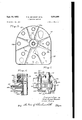
- Figure 5 is a cross-sectional view through the axis V---V, Figure 2, showing a plan View of the motor drive mechanism of the laundering machine;
- Figure 6 is a fragmentary top plan View of the gear casing with the cover removed to show portions of the gear drive mechanism for the agitator and basket portions of the machine of the present invention
- Figure 7 is a fragmentary cross-sectional view through the axis VII-VII, Figure 6;
- Figure 8 is a fragmentary cross-sectional view through the axis of VIII-VIII, Figure 6;
- Figure 9 is an enlarged fragmentary crossrsectional view through the axis IXIX, Figurev 5, and showing some parts in side elevation;
- Figure 10 is a top plan view of the yoke and annular disk portions of the present invention.
- Figure 11 is a fragmentary cross-sectional view like Figure 6 but showing the clutch mem her in the disengaged condition
- Figure 12 is a diagrammatic illustration showing the cycle of operation of the laundering ma.-
- Figure 13 is a diagrammatic view showing the control cams and the electrical circuit arrangements produced by the same during the cycle of operation of the machine of the present-invention;
- Figure 14 is a cross-sectional view of the float structure of the laundering machine taken through axis XIV-XIV, Figure 3;
- Figure 15 is a top plan view of the support plate structure of the present invention.
- the laundering machine comprises a tub portion T which defines a clothes laundering chamber and is supported by the support'structure S.
- the support structure S is covered'in its rear portion by a shroud 20 which extends upwardly behind the tub T to enclose the operating structures extending up to the top of the unit.
- the outer covering of the support S snugly fits the tub T to form a sanitary and attractive shape 'as will be evident from the figure.
- the portions of the tub and support structure exposed to view and the shroud are given a coating of vitreous enamel or similar material to present an attractive readily washed surface.
- the tub T contains a cylindrical inner rotatably mounted clothes container or basket 22,
- FIG 4 together with an agitator 24 mounted concentrically therewith for oscillating motions during clothes washing and rinsing
- An upper housing structure 26 is attached to the upper periphery of the cylindrical outer tub structure 28, Figure 4, and is of generally'annular shape withan inner downwardly extending chute portion 30 to guide clothes or other objectsinto the basket 22.
- a circular cover or cap 32 fits .on the upper portion of the structure 26 and is provided with a handle' 33 to facilitate removal thereof to place clothes in the machine or to remove the same therefrom.
- the support structure 3, Figure 1 sustains the tub portion T in position and, inaddition, conperature control :switch38, Figure 2, and the fluid l temperaturercontrol valve 98; Figure 2, are mounted.
- These contacts are mounted in a com! mon plane perpendicular to the axis of the shaft .50 and are located relative to the length of this shaft at a point such that when the shaft is de-' pressedthe contacts engage the disk 48 and thereofzthe support structure S.
- the shroud forms a horizontal topsurface 4i! Figure .1; in
- the conductor 18 is connected to the conductor 50 through the float switch -86 which is in the position shown in Figure 12 when the liquid level in tub T is below a predetermined level; thereby connecting conductors 88 and 1 1i.
- the solenoids 80 and 82 are connected to-jthe source of electrical energy through the-switches i6 and 18, respectively, the former being com 7 nected in circuit through the switch 66 and th is open and for that reasonthe element does not operate.
- the cycle control switch 36 may, for example c'om prise a plurality of cams,jl22, I06, 64, etc. with associated switches I26, H 4, 58, etc. in cooperative engagement therewith foropening and closing movements as the cams are rotated; 'The cams are mounted-on a common insulated shaft 50 which'is driven by y the timer motor I08 which, for the -particular embodiment of the present invention here described, is a synchronous alternating current motor capable of rotating the shaft 50, one-revolutioninapproximately min.-
- cams 122, ltdtketcsare aligned relative to the s'haftffiiifto provide the desired sequence of control and the knob- 44 'isprovided with suitable' markings'tofindicate the point on the operatingycycle to which the; shaft is aligned or set.
- This valve includes hose couplings '98cand 98b tore ceive hose. co'nnections'xto sources of hotvand; cold water respectively; and'is connected to a hose I09 which supplies water'to the tub T through thehoop-shaped tube-192;,
- hose couplings '98cand 98b tore ceive hose. co'nnections'xto sources of hotvand; cold water respectively; and'is connected to a hose I09 which supplies water'to the tub T through thehoop-shaped tube-192;
- timing motor I08 When the fluid in the tub T actuates the fluid control switch 80, the timing motor I08 is energized through the circuit comprising this switch, conductors 90 and I04, motor I08, conductors III] and H2, suds pump motor I24, and conductor 84 to prong 56b of plug 56 and from prong 56a of plug 56 to conductor 58, switch 46 to conductor 88 and switch 86. Since timing motor I 08 is only large enough to produce the limited torque required to rotate the shaft 50, its current requirements are very small as compared to those of the suds pump motor I24. Hence, motor I08 operates as if connected directly to the line and thus drives the shaft 50 in the direction indicated to cause the operating cycle to progress. The relatively small current flow through motor I24 is insufficient to produce significant torque and consequently suds pump motor I24 does not tend to operate.
- a drain. period .of for example, six minutes follows.
- the "switchl I0 rides out of notch I'I2b of the cam I I2 and opens to deenergize the actuator solenoid I09.
- this causes the agitator 24 to be mechanically disconnected from motor 54 to discontinue the oscillating movements thereof and at the same time mechanically engage motor 54 and the auxiliary pump I28, Figure 4, to cause the latter to rotate in a direction to pump fluid out of the tub T.
- the laundering machine may be operated with a reduced quantity of water by manually turning the knob to a position in the fill period, and depressing the knob to cause the valve solenoids 80 and 82 to be energized in accord with the water temperature desired to cause water to flow into the tub T.
- the knob 44 may be manually rotated to a position beyond the fill period but still in the wash period to deenergize the valve solenoids 80 and 82 and cause the agitator to operate despite the fact that the level --control switch 86 is not lifted. In this manner small quantities of clothes may be washed without re- 7 quiring the time or water necessary for a full quantity of clothes.
- the switch H8 rides in the notch I20a of cam I20 and closes to actuate the two-way valve solenoid II6.
- the resulting current flow insolenoid IIB causes the two-way valve to connect the tub T with the storage reservoir provided to hold the used Washing suds. Consequently, the operation of pump I28 causes water to be pumped out of tub T and into the storage reservoir.
- the extractor solenoid I30 is energized by the circuit through conductor I32 and switch I26, the latter being rendered conducting when it rides on the notch I221: of cam I22.
- energization of the extractor solenoid I 38 causes the basket 22 to be mechanically connected to the motor 54 through a slip clutch assembly which limits the torque exerted on the motor and associated parts of the drive mechanism.
- the cam I34 is positioned to align the notch I34a with the switch I36 and thus permit that switch to descend and make contact when the face of the auxiliary cam I34a rides against switch I36.
- the latter cam is driven by suitable driving elements (not shown) to rotate one revolution per minute and hence execute two revolutions in the two-minute period the notch I34a is aligned with the switch I36.
- the flat face of cam I34a is shaped to permit switch I36 to close during only a short period as, for example, 7 seconds of this time, thus causing the clothes to be sprayed only a rela-,- tively short period of time.
- the spray water is relatively cool fresh water obtained from the temperature control valve 98 when only the solenoid B0 is energized and washes the wash Water ofi of the clothes or other objects contained '9: and opens switch t, therebydisconnecting motor 54 from thesource or energizingpower since the-level control switch 86 is in the down position'shown in Figure 13.
- the cam t t'q ha'srotated to align cam 134v with switch 1st conductor Hi4.
- Shaft 50 then rotates and the agitator solenoid becomes energized toy-reason: or the alignmentof'thenotch H-Za of'cam. H2 with th" "switch I-l-.- I This causes agitator 24,- Figure 4, to' 'e'xecute oscillating motionsto rinsethorou ghly the clothes contained in-the basket 22'.
- solenoid i 69 further cause's themotorse tobe mechanicallyengaged with prim-p 128,Eigure-5,-as is described in further detail hereaften and causes this pump to rotate-in direction: to withdraw water-from tub I. Since the twosway valve solenoid H6 is, not
- the. interior ofthe tub T is iii-fluid. communication with the. drain pipe (notishownl through. the pump'l28 and the two-way valve, and rotation of the pumpv I28 causesthewater to: be pumped: from the tub. T to the-drain pipe...
- the conductor 88 switch I26 connecting conductors lo and .1 l2 inathis period by reason or the fact thatit rides onthe nib 122a vof cam 22..
- the tWOrWay valve solenoid I I6 is energized at this time' through switch IlB which rides in the notch 12% of cam" Zihthusshiitingthe twoway valve to connect the storage reservoir with the; tub T and thereby enabling the sudspump to draw. water from the storage reservoir? to the tub Tlanclfill the latter.
- the cycle" control switch is. in the position indicated at A, Figure '12, the timing motor 58 is-.fenergize'd through thev circuit including. conductor.” 5& conductor 88,.
- the motor 54 doesnotopcrate during this; period becausethe relatively small current flow through the windings thereof isinsufiocient' to develonsignificant torque, therein. -1-Theforegoing conditions prevail so'long as the switch I 2&rides on the nib ⁇ 22a of cam 2-2, at time period that may. for example, continue for threeminutes. If this time period expires before the tubJT is filled-, the fill period, Figure 12', begins and the cycle previously discussedcomm nse theii t in h operation e s t addition-0i fresh; water through; the temperature control valve 93; : Figure 2, to cause the level of the water in thewasher torise to the-level;- fixed by the level control-; switch. 86.
- the main drive motor .54 is mounted on a bracket 5% attached to the rear portion of the vertical support member r50; seen in crossesection in the upper right hand portion of the view of Figure 5.
- the motor, together with the support member It! may also be'seen inthe rear View of Figure 2 and, aswill be further evident from this View, it is mounted in a pairot elongated: slots tfitroby support bolts 54g.
- a pulley 54o isattached to motor 54*and engages the belt'I52 which en circles the actuator drive.
- FIG. 6 is a top plan view of the housing I60, Figure 5, with the top portion removed.
- the shaft I54a upon which pulley I54 is mounted is shaped to form a pinion inside housing I60 and drives the bull gear I62 which is in turn supported on shaft I62a.
- a connecting link I64 is pivotally attached by pivot I64a to gear I62 and by pivot I64b to'the sector gear I66 located in the opposite end of housing I60. This causes sector gear I66 to execute oscillatory motions as the pinion I54a is rotated by pulley I54.
- the sector gear I66 ismounted upon shaft I68 which engages shaft I68 which extends'through the housing I60 and supports the control unit I10, Figure 5, upon its open end.
- the sector gear 166 further engages the pinion I12 which is splined to shaft I14, which shaft extends upwardly to form the inner shaft of the tub T, Figure 4.
- the pinion gear I12 has a plurality of notches I122) at its lower hub portion.
- the pins I12c are normally received in these notches for driving shaft I14 from pinion I12.
- This mechanism is best seen in the cross-sectional view of Figure '1, which is taken along axis VIIVII, Figure 6, and shows shaft I14 in elevation with pinion I12 thereon.
- the sector gear I66 may be seen in elevation behind and to the left of the pinion I12.
- the upper hub portion of pinion I12 is provided with a peripheral recess I12a which mates with the bifurcated end portion I18a of the operating arm I18, which arm is supported from the shaft I80.
- the shaft I80 rests in the recess I60a of housing I60 and bears anopening or slot IBM to accommodate the operating arm I16, which may be seen in cross-section in Figure 7.
- the shaft I80 is provided with a roller I80b which rides'on the arm I16 to minimize friction as arm I16 is shifted.
- the pinion I12 is likewise lifted by the arm I18 and is shifted out of engagement with'the-pins I12c, thereby discontinuing oscillation of shaft I14.
- the operating arm I16 engages or disengages the pump I28.
- This operation is achieved through the crank I82 and the links" I83 and I83a, Figure 5, which couple this arm to the rocker 'arm I84h which rotatably supports idler pulley I86h on its remote end.
- the rocker arm I84h. is rotated to swing idler pulley I86h to a retracted position where it does not engage belt I52 and permits that belt to pass over the pulley I56 without engaging that pulley.
- pump I28 is not rotated.
- the position of the arm I16 is controlled by current flow in the actuator control solenoid I00 whose function has previously been described under operation.
- the method by which this control is achieved may best be seen from the fragmentary side elevational and cross-section view of Figure 8, which shows the operating arm I16 in elevation and portions of the housing in cross-section, as seenjfrom the axisVHI VIII, Figure 6.
- the solenoid I09 is provided with a centrally disposed magnetic plunger I09a of iron or other magnetic material and upon which the pin I0!!!) is mounted.
- the operating arm I16 has two parallel elongated slots I84 and I86 to receive pin I08b, these slots having their opposite ends abutting inform a vertical slot portion I88 connectingthem.
- the arm I16 is shaped to form hooked notch portion H60. in which the shaft I80 may descend to 'permit pinion I12 to shift to an engaging relationship with the pins I12c.
- an upwardly extending pin I16b is located upon the upper surface of the operating arm I16, which pin rides in a corresponding opening in the link I82 to shift-that link in accord with the movements of the operating arm I16.
- thearrn I99 is shaped to form a slot. I9ila, Figure 9, upon which the post I92 rides.
- the post I92is supported 'frorn the housing I99 by :the bracket I94 and is'providedwith a roller I92a. to reduce the frictionincident to. shiftingof armISfl.
- the bell-shaped member I so is carried bra diamond-shaped yoke 299- which -i-s--mountedforwhen the arm I96 ismoved forwardly to; raise.
- qnlthy iie .9 20 provid a snugsuoportiforthe oke '20 im ar y; spring 1:920 encircles the; n; I 9.21). qfgthe pestle? and bottoms against the-und r ortionotthe Support-plate 3e and the.
- Pins 29.5 arelposition'ed in the extensions 294s of disk zfl i and. the turnedLup portion 290a of the yoke 209 pivotally tosupport disk 294 from the yoke 290.
- disk zoe is'restrainedagainst rotation with-shaftulilfi and rfollowsx..the axial movementsof'the yoke 290.2.
- the collar 2:98 is. in 'splined engagement with the upper splinedportion I 94?) of' the clutch member I94 and consequently rotatesxwith that: member and the shaft I99. It is provided with the brake surface: 298a on its bottom portion to engage the disk- 294 and has a. plurality of cups 2081), Figure 5, to receive the'springs 210, In the particular structure shown in the figures-a total of four springs 2H] and a'corresponding number of cups" 29917 are provided as will'beseen from Figure 5; which is a view looking down on;
- the bushing IISBJiS-likeWiSe' provided with aplurality of cups l98a,to'receivethe.- opposite ends of the springs 2J0; These springs, bottoming against-bushing I98, which is fixed axially to shaft I96 by the setscrew I980, and againstcollar 298, force the collar 298 against: the seat 299 of the bell member I99 as previously; described andthus cause frictional engagements: between the friction surface I94a off the'clu-tch member I 94' and theflpulley I 58. l
- the upper surface of the bushing I984 issurfaced with an, annular friction disk: I98b. disk rides against the. lower portion ofthecentral post 2795, and opposes lifting of-shaft- I196. In addition it formsv a. supplementarybrake against; the. latter when, theaxial pressure exerted byathe;l dish: 2.04 is: sufficient to. overcome their weighteof the basket and other elements suspended on shaft I96.
- the pump I28 is connected by hose 2I0 to sump 2I2 which is in fluid communication with the interior of the tub T.
- the opposite side of this pump is connected by hose 2I4 to pump 224 which is connected to housing 2IB which defines a fluid chamber in communication with the two-way valve 2IB.
- This hous ing is best seen in the side elevational view of Figure 4.
- the two-way valve 2! is provided with hose couplings 248a and 2I8b, one of which is connected to a storage container such as a laundry tub and the other of which is connected to a drain.
- the valve 2! is constructed normally to connect the chamber defined by member 2 I B with the drain, but when current flows in the solenoid IIB the linkage 220 shifts the rocker arm 222 and connects the chamber defined by member '2I6 to the storage container.
- the chamber 2I6 is further in communication with the suds pump 224 which is electrically connected, as indicated in Figure 8, and which isoperated in timed sequence as previously explained.
- the chamber 2I6 provides priming fluid for this pump and enables it to pump fluid back into the tub T throughthe hose 2M, pump I28, hose2
- One of the features of the present invention resides in. construction of the base plate 34 of the support structure S to sustain all the various operating elements, including the switches 36 and 38;and the temperature control valve 98, and as well as the cylindrical tub T.
- the plate 34- is shaped to form a semi-circular for- Ward'portion 31, Figure 15, of radius corresponding to the radius of the cylindrical tub T to blend with or meet the forward portion of the tub and form an attractive overall structure, and a rectangular rear portion 39, which extends behind the tub T to define a surface upon which the various operating elements may be mounted.
- the support or base plate 34 is'mounted upon the four mounting posts I59, I59a, I53b, I520, and I50d which maybe seen in cross-section in Figure 5 and from which plate 34 is sustained in'flxe'd position to support the various elements mounted upon it.
- a semi-circular shroud I5I, Figurel forms'a skirt about the semi-circular forward portion 31 of member 34 and meets the outer surface of the tub T to form a neat, attractive, structure.
- the shroud 20, Figure 1 covers the rear portion 39 of member 34 and defines a relatively fiat upper surface 40 which forms a mounting surface for knobs 42 and 44.
- a plurality of upstanding portions 34a are pressed in base plate 34 and rise above the general level thereof to form seats upon which the outer portion 28 of the tube T is mounted. This mounting is achieved by a plurality of screws 35, Figure 4, which seat on waterproof washers 35a.
- the outer portion 28 of the tube T extends inwardly at its under portion 28a and is attached to the central post 236 by a plurality of bolts 28b positioned at intervals about the inner periphery thereof. These bolts pass through openings in.
- the base plate 34 is further provided with a plurality of downwardly extending stamped depressions 33, Figure 15.. These extend radially about. ,the axis of shaft. I14 and impart further 16 rigidity to the plate 34. One of the depressions is seen in cross-section in the view of Figure 9.
- a further feature of the present invention resides in the use of hook-shaped pipe I02 which is connected to the fluid. temperature control valve 98 by hose I00. As shown in Figure 2, this pipe extends over the edge of tube T and projects downwardly over the opening formed in the upper housing structure 26 inside the upturned portion26a which may be seen in elevational view in Figures 2 and 4. This pipe defines a passage for water flow from the source of clean water connected. to control valve 98 and which opens at a level well above the maximum water level in the tube T so that the fluid therein never comes in contact with this passage.
- the shroud 20, Figure 1 which covers the control valve-98 and the hose I00, has a housing 40a on its flat upper surface 40.
- This housing is shown in cross-section in Figure 4. This encompasses the hook-shaped pipe I02 in the region it passes over the edge of tub T and provides a neat, attractive, cover for the same.
- the level control switch and the structure in cooperation therewith is best seen in the views of Figures 2 and 4, together with the cross-sectional views of Figures 3 and 4.
- the level control switch is pivotally attached-to the lever 226 which in turn ispivoted by cotter pin 226a to the downwardly directed float bell 228.
- Thisrbell fits in housing 230 supported from the outside ,of'the tub T and which is in communication therewith through opening 232;
- the bell 228 isweighted by the sleeve 228a,- Figure 14.
- Gne of the features of the present invention resides in the selectively operable friction drive mechanism provided to drive the basket 22 from the motor 54.
- the basket 22 particularly when loaded with afull load of damp clothes, possesses a large moment of inertia and resists with relatively great torque any attempt to accelerate it quickly.
- any-water in the tub T opposes rotation and acceleration of basket 22.with' relatively great torque. If a direct drive is made between the motor 54 and the basket 22 it would be necessary to use large expensive high starting torque and high pull out torque motors.
- the whole mechanical system would have to be designed to withstand these relatively great torques during acceleration of the basket 22 during the extracting or drying operation.
- This pulley and transmitting drivin rq h r fr m mechanism is ordinarily required to prevent conlimited by the force of aid springs, said means I nection of the motor 54 to the basket 22 when Connecting id yoke with said clutch member th t b T t i water Since any attempt t for disengaging said clutch member from said drive the basket under such conditionsoverloads pulley eompnslng a brake ringv secured to said 7 the motor 54 and results in its stalling, with yoke and r l g aid clutch member and machine for clothes and the like comprising a the consequent overheating of the'motor burn- 25 held r rotation With respect e eto and ing of fuses, etc.
- the apparatus of the present i a by Said o into e ent with said invention eliminates such low level float control frictlon disk on the bottom of said second ring t t encountering t dimculty since the to release said clutch member and to hold said ciutch comprising beii e 94 and pulley sleeve from rotation, and also moving said first-
- a drive mechadlsknism for the basket 22 is deliberately chosen to In combmatlon Was/11mg and rac in have limited torque capacity to obtain economachine for clothes d t e like comprising a mies associated with a low capacity drive.
- a basket mounted Wlthln S d tub for r0- interposing t clutch formed by bell member tatable movement therein about a vertical axis, I94 against pulley I58, and arranging the f an agitator within said basket, drive mechanism tion surface [94a and the spring constant of for oscillatably driving said agitator including Springs limit the maximum torque trans- 40 a vertical shaft having said agitator mounted mitted thereby to a value less than the capacity thereon and extendmg downwardly b eath Said of the drive, the drive is protected from overb fi basket, other ⁇ irlve echanism for load and at the Same time effe tiv driving spinning said basket including a sleeve encircling action is achieved Moreover it becomes said vertical shaft and extending downwardly necessary to-use alow level float control mechabeneath the top of e tub and basket, a i y nism in the machine since the clutch will slip freely m on sald Sleeve,
- a second ring by Letters Patent of the United States is: Spaced beneath Said first ring and held in 1' In a combination washing and extracting gagement with said clutch member and against rotation with respect to said clutch member tub, a basket mount within said tub for and having a friction disk on the bottom surface tatable movement therein about a vertical axis, thereof a plurality of Compression pr gs inan agitator within said basket, drive mechanism Ferposiid between Said rings r yi ldably engagfor oscillatably driving said agitator including mg P m Wlth Said pulley nd a vertical sh ft having Said agitator mounted transmitting driving torque therefrom limited thereon and extending downwardly beneath said by the force of said Springs, a y e ncircling tub and basket, other drive mechanism for spinsaid clutch member and having a b a e
Description
pt- 1952 P. E. GELDHOF ET AL 7 2,610,498
LAUNDERING MACHINE Filed Nov. 20. 1947 9 Sheets-Sheet 1 EagtZ.
[fir Q21! UPS Per-5e [bl/JED 62-4000, M tun/5e Envcae Sept. 16, 1952 P. E. GELDHOF ET AL LAUNDERINQ MACHINE 9 Sheets-Sheet 2 Filed Nov. 20. 1947 fUVEfif JFE Parse d-Tn meo 6210/10! lurmee 194/052 by JZ f 3/ 5.-
Sept. 16, 1952 P. GELDHOF ET'AL 2,610,498
- LAUNDERING MACHINE 7 Filed Nov. 20, 1947 I s Sheets-Sheet 4 frzz ez-ziar' s Pare: t'buneo G'amvar [an 5.9 ,envcee Sept. 16, 1952 P. E. GELDHOF ET AL LAUNDERING MACHINE 9 Sheets-Sheet 5 Filed Nov. 20. 1947 [NI E17 iars Parse [00020 661000, Zwwne Emcee Sept. 16, 1952 P. E. GELDHOF ET AL Q 2,610,493
LAUNDERING MACHINE Filed Nov. 20, 1947 9 Sheets-Sheet 6 P6752 [Bu/Leo Cam/or LUTHER 191N054? Sept. 16, 1952 P. E. GELDHOF ET AL LAUNDERING MACHINE 9 Sheets-Sheet 7 Filed Nov. 20. 1947 52 z Pu Sept. 16, 1952 P. E. GELDHOF ET AL 2,610,498
LAUNDERING MACHINE Filed Nov. 20, 1947 9 Sheets-Sheet 8 AGITATUR RINSE EX TRACT WA 5 H RINSE WA ER MINUTES |2345i789|0l| I3H|5 WIN! 2 WAY VALVE SUDS PUMP AGI TATOR MIX. WATER HOT WATER MOTOR SWITCH EXTRACTOR SPRAY Livel- 76 'com'wol. 78 f 94 5a J l34dr V341 62 'A 11m: n01 WATER zwn'vALv: mum'm nrnp 5318 61020 46 .m ass :2
' hVEfifDfE Pans-e [bl/32o 6'52 on; Zurmse BIA/see Sept. 16, 1952 P. E. GELDHOF ETAL LAUNDERING MACHINE Filed Nov. 20, 1947 s Sheets-Sheet 9 Patented Sept. 16, 1952 Peter Eduard Geldhof and. Luther Ringer, St. Joseph, Mich, assignors to Whirlpool Corporation, acorporation of New York Application November 20, 1947, Serial No. 787,060
(oi..6s 2s)' 2 Claims.
This invention. relates to automatic clothes I washing, rinsing, and drying machines and more particularly to an improved structure therefor;
In one form of automatic laundering machine, mechanism is provided whereby the user may insert clothes or other objects to be laundered','.set the controls ofthe machine to initiate the launderingzcycle, andreturn at a later time to find the clothing or other objects completely cleansed, and rinsed and the preliminary. drying or water extracting operation performed. Such. mechanismis of particular utility for home use as .it relieves the burdensomeness of laundering or cleaning processes and obviates the necessity of constant attention on the part of the user. In the machine of the present invention a tub isprovided in whichis rotatably mounted a cylindrical clothes supporting basket. In addition, an agitator ismounted for oscillatory movement within the basket. Mechanism is provided to drive theiagitator in oscillating movements for washing and rinsing clothes in the basket when the tub is filled with water and to rotate the basket at high speed to extract water centriiugally from the clothes when the tub hasbeen drained. Automatic control elements. are provided to. fill the tub, energize the agitator for clotheswashing. movements, empty the tub, energize the basket for preliminary extracting movements to remove the wash water from the clothes, spray fresh water on the clothes during the end of. this preliminary water extracting movemenufill the tub'with fresh rinse water, energize the. agitator 'toassure complete exposure of the clothing or drive; and control .elements' located inthefsupport:structure- ."ihe support structure is of semi cylindrical" shape "at: its forward portion. and: blends into-thecylindrical'shapebithe, tub, At
its rear portion;-=-the support structure is rectangular in shape. ;.A*horizontallyj disposed base plate "extends beneath, the tub and back to. the
rear portion of the unit to form. ashelfupon which; 1 the, contrclgswitches' and valves. are
mounted- Q I r Further in throusnian.axial ymovable-rotati g memberpn the shaft thereof which in one extreme of movementv causes gdriving engagements and in the other extreme of movement. causes braking engagements. vWhen it is desired to drive the basket, this member is axially shifted frictionally to engage the main drive mechanism to form a slipping clutch engagement that limitsthe torque applied to the drivingmechanism during the time the basket is being brought up to speed.
.This torque limitation enables the use of a motor tub to. supply water thereto.. This tube is cone.
nected. at one end to. the automatic fluid. mix.- ing .valve which is disposed on thehorizontal plate of the support structure. and extends .over the edge of the tub to a level well above.- the maximum height of the fluidtherein. By. this means an inexpensive, reliable, methodof filling the tubis provided, and in addition the possibility of. dirty wash water backing up into thewater supply pipes is eliminated. l.
In accordance with another feature of .the present invention the laundering machine is pro..- vided with automatic control elements operable in one position, to cause the agitatorto operate only 'when'the. waterlevelin the tub exceedsa p de erm ned mi mum and in another position to energize the agitator for operationregardless of the water'levefl in the tub. Automatictiming mechanism is provided to shift the control e'lements from one position to the other under normal laundering operations but, when desired, tlfe controlelements may be shifted manually to permit Washing With the tub partially filled with water. This feature is desirable when-the machine is used to wash a small number of clothes not justifying the use of a full tub of -water -or requiring as long a time period for washing as v in the case of a fullloadot clothing.
a mice. ith h pre nt in- 1 ventionithe basket is selectively driven or; braked A structure having features in common with the. features of the present invention is described and claimed in the pending application of Peter Eduard Geldhof and Luther Ringer, entitled Automatic WashingLBinsing and Drying Machine? Y the present.inv n i ns.
to thesame assigne s1 chine wherein the automatic elements are easily exposed for repair or replacement.
Still another object of the present invention is to provide an improved automatic laundering machine wherein the base portion provided to support the tub also cooperates with the tub toform a unit that is readily enclosed by a suitable shroud and skirt to form a simple and artistic" structure having a clean, attractive appearance. Yet another object of the present invention is to provide an improved laundering machine wherein a relative low starting and pull-out torque motor mav be used but in which a mini.- mum of automatic level controls are required.
Another obiect of the present invention is to provide an improved laundering machine wherein clutch elements are interposed between the driving mechanism and the rotatable basket portion to limit the torques exerted on the driving mechanism.
Yet another obiect of the resent invention is to provide an im roved clothes launderin machine which normallv o erates with a redetermined ouant tv of water durin the washing process but may optionally be o erated with a smaller quantity of water to accommodate a relatively small nuant tv of clothes.
7 Still another obiect of the present invention is to provide an impro ed clothes laundering machine havin automat c control elements o erable to conduct the. laundering c cle with a predetermined ouantitv of water b t which may be operated manually to ca se the launder ng cycle to progress with a smal er ouantitv of water.
The novel features which we believe to be characteristic of our invention are set forth with particularity in the appended claims. Our invention itself, however, both as toits organization and method of operation will best be understood by reference to the following description taken in connection with the accompanying drawings.
- In the drawings Figure l is an isometric 'view from the front of a complete automatic laundering machine constructed in accordance with the principles of the present invention;
Figure 2 is a rear elevational View of the mechanism of Figure 1 with the shroud and portions of the rear cover removed to expose portions of the control elements to view; 7 r V Figure 3 is a cross-sectionalview of the mechanism of Figure 1 taken along the axis III--III, Figure 2;
Figure 4 is a side elevational view of the mechanism of Figure 1 with portions of the shroud broken away to show the various components of the mechanism, and the spindle and associated parts in cross-section to show the construction of the agitator and basket and the drive mechanism therefor;
Figure 5 is a cross-sectional view through the axis V---V, Figure 2, showing a plan View of the motor drive mechanism of the laundering machine;
Figure 6 is a fragmentary top plan View of the gear casing with the cover removed to show portions of the gear drive mechanism for the agitator and basket portions of the machine of the present invention;
Figure 7 is a fragmentary cross-sectional view through the axis VII-VII, Figure 6;
.Figure 8 is a fragmentary cross-sectional view through the axis of VIII-VIII, Figure 6;
Figure 9 is an enlarged fragmentary crossrsectional view through the axis IXIX, Figurev 5, and showing some parts in side elevation;
Figure 10 is a top plan view of the yoke and annular disk portions of the present invention;
Figure 11 is a fragmentary cross-sectional view like Figure 6 but showing the clutch mem her in the disengaged condition;
Figure 12 is a diagrammatic illustration showing the cycle of operation of the laundering ma.-
chine;
Figure 13 is a diagrammatic view showing the control cams and the electrical circuit arrangements produced by the same during the cycle of operation of the machine of the present-invention;
Figure 14 is a cross-sectional view of the float structure of the laundering machine taken through axis XIV-XIV, Figure 3; and
Figure 15 is a top plan view of the support plate structure of the present invention.
As shown on the drawings:
The laundering machine comprises a tub portion T which defines a clothes laundering chamber and is supported by the support'structure S. The support structure S is covered'in its rear portion by a shroud 20 which extends upwardly behind the tub T to enclose the operating structures extending up to the top of the unit. The outer covering of the support S snugly fits the tub T to form a sanitary and attractive shape 'as will be evident from the figure. The portions of the tub and support structure exposed to view and the shroud are given a coating of vitreous enamel or similar material to present an attractive readily washed surface.
The tub T contains a cylindrical inner rotatably mounted clothes container or basket 22,
Figure 4, together with an agitator 24 mounted concentrically therewith for oscillating motions during clothes washing and rinsing An upper housing structure 26 is attached to the upper periphery of the cylindrical outer tub structure 28, Figure 4, and is of generally'annular shape withan inner downwardly extending chute portion 30 to guide clothes or other objectsinto the basket 22. A circular cover or cap 32 fits .on the upper portion of the structure 26 and is provided with a handle' 33 to facilitate removal thereof to place clothes in the machine or to remove the same therefrom. l The support structure 3, Figure 1, sustains the tub portion T in position and, inaddition, conperature control :switch38, Figure 2, and the fluid l temperaturercontrol valve 98; Figure 2, are mounted. Stamped metal sheets are formed :to provide shrouds :20'and. I51. encompassing the portions :01 the support structure .8 located underneaththetub T andoovering the rear portions 46 vfor cooperative engagement with the two oori= 'tacts 512. These contacts are mounted in a com! mon plane perpendicular to the axis of the shaft .50 and are located relative to the length of this shaft at a point such that when the shaft is de-' pressedthe contacts engage the disk 48 and thereofzthe support structure S. Moreover, the shroud forms a horizontal topsurface 4i! Figure .1; in
horizontal" alignment. with the cover-32 of the tub portion T. Operating handles 42 and '44 for the temperature controlswitch 3:8 and the cycle control switch 36; respectively, extend through this top surface of shroud 26 to provide a'conby provide a closed circuit for the passage of electricalcurrent. r Whenthe .knob 44 is rotated to the-condition corresponding to the beginning of the .fill period, theswitch-fifi rides inthe notch 62a of the cam "52 and the switch 68 rides in the notch 64a of cam 4. Switch -58 thereupon drops down to connect conductor "3 to conductor -12 and the switch, :66 :drops down to connect conductor 10 to conductor 14. Conductors-i2 and 14' are connected'to switche 16 and'ifi which ,in turn are venient readily adjustable, means for controlling the operation of "the, laundering machine.
4 Operation 7 The, features of the present invention can best be understood by a preliminary discussion of the operating cycle thereof taken in connection with Figures 12 and 13. Figurelzisa diagram indicating the condition of the cam actuated switches controllingthe energization of the variouselements identified thereon at the various times in the operating cycle, these times being identifiedby the indications in the minutes line of the diagram. It will be understood, of course, that anelement may be indicated as energized on the-diagram of Figure 12 when in ft'act some other portion'of the, energizing circuit connected to the mix watersolenoid 8B and the .hot water solenoid .82, respectively.- These sole noids are connected on their opposite ends to the conductor 8d which is in electrical connection 7 with the prong 56b ofplug 56.
The conductor 18 is connected to the conductor 50 through the float switch -86 which is in the position shown in Figure 12 when the liquid level in tub T is below a predetermined level; thereby connecting conductors 88 and 1 1i. Thus-when the unit is energized by depressingytheknob 44, the solenoids 80 and 82 are connected to-jthe source of electrical energy through the-switches i6 and 18, respectively, the former being com 7 nected in circuit through the switch 66 and th is open and for that reasonthe element does not operate.
The cycle control switch 36, shown diagrammatically in Figure 1'3', may, for example c'om prise a plurality of cams,jl22, I06, 64, etc. with associated switches I26, H 4, 58, etc. in cooperative engagement therewith foropening and closing movements as the cams are rotated; 'The cams are mounted-on a common insulated shaft 50 which'is driven by y the timer motor I08 which, for the -particular embodiment of the present invention here described, is a synchronous alternating current motor capable of rotating the shaft 50, one-revolutioninapproximately min.-
' ties. The cams 122, ltdtketcsare aligned relative to the s'haftffiiifto provide the desired sequence of control and the knob- 44 'isprovided with suitable' markings'tofindicate the point on the operatingycycle to which the; shaft is aligned or set.
In thevinv of'Figurelil, the shafted and the assoeiatedramsare rotated by motor m3 in-the direction in icatedby; the arrows 50a and *the shaftisshown as rotated tothe position corre 7 anayi forgexample,"comprise a conducting disk'flB, \attached to ithexin'sulated shaft 50 of 'the switch latter through the switch 66.
The switches 76 and 18 are actuated bylca'ms 92 andliturespectively, and which are mounted on the insulated shaft 96 of the temperature control switch 38 to which knob 42 is. connected; This knob may be rotated to any-oneof three positions, a first positioncorresponding to; closure of both switches 75 and 18, (the position indicated in Figure 13); a second position corresponding to closing of switch l6, and a third position cor-v responding to closing of'switch 18.; This action is achieved by providing notches 94a and 94b in the cam plate r94 and notches 92a and 92bin=the cam plate 92, the notches Mband 92a being aligned relative to-the shaft 96 so that whenthe ed above the'temperature control. valve 98. This valve includes hose couplings '98cand 98b tore ceive hose. co'nnections'xto sources of hotvand; cold water respectively; and'is connected to a hose I09 which supplies water'to the tub T through thehoop-shaped tube-192;, When electric current iszcaused to flow through mix -solenoid 80, forexample, a movable plungeriis raised by the magnetic forces associatedwithtthe current flow el'ementsiinjthelvalve 98tto iarelatively low terns, perature-rto cause relativelyf cool water lto:,fl'ow intosthe tub T.. On'thev other handxwhenthe -hotrso1en'oid"i82 is. energized with'ilelectric .current', the coupling 98a, whichis attached to a source of hot water (not shown), is connected to the hose I to cause hot water to flow into tub T. When both solenoids are energized, water of intermediate temperature passes into the tub T.
From the foregoing it will be seen that when the knob 44 is depressed to energize the mechanism at the start of the laundering cycle, liquid of temperature regulated in accordance with the setting of the temperature control switch'38 flows into the tub T. When the required amount of water passes into the tub, the level control switch 86 disconnects conductors 88 and 10, Figure 8, and thereby causes this fluid flow to discontinue.
. When the fluid level in the tub T rises to the point where level control switch 86 disconnects the conductors 88 and I0, the conductors B8 and 90 are connected with the result that motor 54 is energized through the circuit which can be traced from the prong 56a of plug 56 to conductor 58, switch 46, conductors 60 and 88, level control switch 86, conductors 90 and I04 through motor 54 and finally back to prong 56?) through conductor 84. Moreover, the cam switch H0 in the fill and wash condition (Figure 12) is in the closed position because notch I I2?) of cam I I 2 bears thereagainst during this period. This completes the electrical circuit from conductor I04 (which is energized through the level control switch 86) switch H0, agitator solenoid I09, and conductor 84. As will be described in further detail hereafter, current flow through solenoid I09 causes engagement of mechanical elements which drive the agitator 24, Figure '4, from the motor 54 to cause the former to execute oscillatory or reciprocating clothes washing movements. Thus, upon completion of the filling of the tub T, the agitator is energized to wash clothes contained in the basket 22.
When the fluid in the tub T actuates the fluid control switch 80, the timing motor I08 is energized through the circuit comprising this switch, conductors 90 and I04, motor I08, conductors III] and H2, suds pump motor I24, and conductor 84 to prong 56b of plug 56 and from prong 56a of plug 56 to conductor 58, switch 46 to conductor 88 and switch 86. Since timing motor I 08 is only large enough to produce the limited torque required to rotate the shaft 50, its current requirements are very small as compared to those of the suds pump motor I24. Hence, motor I08 operates as if connected directly to the line and thus drives the shaft 50 in the direction indicated to cause the operating cycle to progress. The relatively small current flow through motor I24 is insufficient to produce significant torque and consequently suds pump motor I24 does not tend to operate.
During the first ten minute period identified as fill, Figure 12, the above described conditions prevail and the agitator operates when the tub T is full. Upon completion of this period, the switches 66 and 68 ride out of the notches 62a and 64a in cams 62 and 64, respectively, and open to disconnect conductors, I2 and "from conductor I0; In addition, the switch II4 rides in the notch [06a of cam I06 to connect conductor.
60 to. conductor I04 to render the operation of motor 54 and timer motor I08 independent of the operation of level control. switch 85 and-the quantity of water in the tub T.
. Upon completion of the wash period which may, for example, extend for a ten minute period afterthe fill period, a drain. period .of, for example, six minutes follows. At this time the "switchl I0 rides out of notch I'I2b of the cam I I2 and opens to deenergize the actuator solenoid I09. As will be described in further detail here-'- after, this causes the agitator 24 to be mechanically disconnected from motor 54 to discontinue the oscillating movements thereof and at the same time mechanically engage motor 54 and the auxiliary pump I28, Figure 4, to cause the latter to rotate in a direction to pump fluid out of the tub T.
Since the operation of the agitator 24 is independent of the level of the fluid in the tub T during the last ten minutes of the wash period,
the laundering machine may be operated with a reduced quantity of water by manually turning the knob to a position in the fill period, and depressing the knob to cause the valve solenoids 80 and 82 to be energized in accord with the water temperature desired to cause water to flow into the tub T. When the desired quantity of Wateris in the tub, the knob 44 may be manually rotated to a position beyond the fill period but still in the wash period to deenergize the valve solenoids 80 and 82 and cause the agitator to operate despite the fact that the level --control switch 86 is not lifted. In this manner small quantities of clothes may be washed without re- 7 quiring the time or water necessary for a full quantity of clothes.
During the suds drain period the switch H8 rides in the notch I20a of cam I20 and closes to actuate the two-way valve solenoid II6. As will be described in further detail hereafter, the resulting current flow insolenoid IIB causes the two-way valve to connect the tub T with the storage reservoir provided to hold the used Washing suds. Consequently, the operation of pump I28 causes water to be pumped out of tub T and into the storage reservoir.
During the last portion of the suds extract period, the extractor solenoid I30 is energized by the circuit through conductor I32 and switch I26, the latter being rendered conducting when it rides on the notch I221: of cam I22. As will be described in further detail hereafter, energization of the extractor solenoid I 38 causes the basket 22 to be mechanically connected to the motor 54 through a slip clutch assembly which limits the torque exerted on the motor and associated parts of the drive mechanism.
During a short interval of the suds extract period, as, for example, the minutes twenty-four and twenty-five (Figure 12), the cam I34 is positioned to align the notch I34a with the switch I36 and thus permit that switch to descend and make contact when the face of the auxiliary cam I34a rides against switch I36. The latter cam is driven by suitable driving elements (not shown) to rotate one revolution per minute and hence execute two revolutions in the two-minute period the notch I34a is aligned with the switch I36. The flat face of cam I34a is shaped to permit switch I36 to close during only a short period as, for example, 7 seconds of this time, thus causing the clothes to be sprayed only a rela-,- tively short period of time. The spray water is relatively cool fresh water obtained from the temperature control valve 98 when only the solenoid B0 is energized and washes the wash Water ofi of the clothes or other objects contained '9: and opens switch t, therebydisconnecting motor 54 from thesource or energizingpower since the-level control switch 86 is in the down position'shown in Figure 13. At this time, the cam t t'q ha'srotated to align cam 134v with switch 1st conductor Hi4. Shaft 50 then rotates and the agitator solenoid becomes energized toy-reason: or the alignmentof'thenotch H-Za of'cam. H2 with th" "switch I-l-.- I This causes agitator 24,- Figure 4, to' 'e'xecute oscillating motionsto rinsethorou ghly the clothes contained in-the basket 22'.
After about two minutes agitation,..which may, for example; terminate at'minute 2B, Figure 12', the "drain-rinse water period commences. At thi's ti met the switch lt'l" no longer rides in the notch l l z'aorcam- 11 2 and opens to deenergize the agitator solenoid H3 9- to cause the agitator: to b'emechanicall y disconnected from motor 54 and discontinue the oscillating motions thereof. Deenergization of agitator, solenoid i 69 further cause's themotorse tobe mechanicallyengaged with prim-p 128,Eigure-5,-as is described in further detail hereaften and causes this pump to rotate-in direction: to withdraw water-from tub I. Since the twosway valve solenoid H6 is, not
energized during: this period, the. interior ofthe tub T is iii-fluid. communication with the. drain pipe (notishownl through. the pump'l28 and the two-way valve, and rotation of the pumpv I28 causesthewater to: be pumped: from the tub. T to the-drain pipe...
Approximate. two minutes after the foregoing draining: operation commences. as, for example,
at minute KLEig-ure IZ the extract rinse water A periodlis started. At this time. the switch I26 rides into'thenotch l22a in cam I22 and thereby connectsconductorilo to the-extractor solenoid I30. As will be describedin further detail hereafter,-;this causes the motor 54 to engage the basket 22 througha slip clutch which operates to limit the torque exerted on the drive mechanism. The basket 22 is thereupon accelerated to a--high rotational velocity as rapidly as. the. slipping ability of the clutch permits and water is driven out of the clothes thereinby the centrifugal forces associated with the rotationalmotion.
I Ii -it; should happen that the pump l 28 does not quite remove all the Water from tub T duringthetwo minutes allotted for this-action, overload of the-drive mechanism isprevented by the slipping clutch interposed between the motor 154 andthe basket 22. Moreover, the pumpl'28 continues-in operation and when the water is-rem'ov'ed: thedrive mechanism is then capable of accelerating the basket 22.. During the drain rinse water and. extract rinse water periods the pump I28 continues to rotate to remove any water iii-the tub T.-
At the beginning of the extract rinse water'periodas, for example, minute 3 l the notch I346 rides against theswitch I36 to energize solenoid-8fi when the flat face-oithe cam: l-34e rides againstthat switch. Thiscausesaspray of about '7 seconds duration during-- the: one-minuteperiod i0 when the notch 7 13M is aligned with. thev switch Upon completion of the extract rinse water period, the entire unit is shut off when camfll'B through the conductor H22, the closedswitch' 1'26.
the conductor 88 switch I26 connecting conductors lo and .1 l2 inathis period by reason or the fact thatit rides onthe nib 122a vof cam 22.. The tWOrWay valve solenoid I I6 is energized at this time' through switch IlB which rides in the notch 12% of cam" Zihthusshiitingthe twoway valve to connect the storage reservoir with the; tub T and thereby enabling the sudspump to draw. water from the storage reservoir? to the tub Tlanclfill the latter. Duringthe time the cycle" control switch; is. in the position indicated at A, Figure '12, the timing motor 58 is-.fenergize'd through thev circuit including. conductor." 5& conductor 88,. level control switch; fifig conducto'ri lit, switch E26,. conductor 1' l 2,..con;ductor l i ii, motor H23; motor 5 and con dilator toitheprong 561701. the plug 516 ;-Since the .rnotor osi has. a horsepowerrating greatly in ex'cesslof the rating of the. tirningi motor. use, the impedance" of" the; windingsxthereof is extremely small" as compared with the impedance of the windings of timingmotor: its. and substantially the entire line voltage appears across the. latter motor and causes it to rotate the shaft or to cause the .cycleof progress. The motor 54: doesnotopcrate during this; period becausethe relatively small current flow through the windings thereof isinsufiocient' to develonsignificant torque, therein. -1-Theforegoing conditions prevail so'long as the switch I 2&rides on the nib {22a of cam 2-2, at time period that may. for example, continue for threeminutes. If this time period expires before the tubJT is filled-, the fill period, Figure 12', begins and the cycle previously discussedcomm nse theii t in h operation e s t addition-0i fresh; water through; the temperature control valve 93; :Figure 2, to cause the level of the water in thewasher torise to the-level;- fixed by the level control-; switch. 86.
V Inthe event the level of thewater rises to the level. fixed by the level control switch 86 while thefsud's pump H liis operating, the level control switch 86 connects conductors and 91K to cause the agitator solenoid its to be energized through switch Ht which is in the closed positionclurin this tfime because it rides in the notch I 12b of cant H2; 1 Clothes washing operations then commence and thela'un'd'ering cycle progresses as previously described.' 1
Structure The main drive motor .54 is mounted on a bracket 5% attached to the rear portion of the vertical support member r50; seen in crossesection in the upper right hand portion of the view of Figure 5. The motor, together with the support member It!) may also be'seen inthe rear View of Figure 2 and, aswill be further evident from this View, it is mounted in a pairot elongated: slots tfitroby support bolts 54g. As will'be evident from-Figure 5, a pulley 54o isattached to motor 54*and engages the belt'I52 which en circles the actuator drive. pulley I54, the pump drive'pulley' I56 and the extractor drive pulley The construction and operation of the agitator drive mechanism will best be understood by reference to Figure 6, which is a top plan view of the housing I60, Figure 5, with the top portion removed. As will be evident from this view, the shaft I54a upon which pulley I54 is mounted is shaped to form a pinion inside housing I60 and drives the bull gear I62 which is in turn supported on shaft I62a. A connecting link I64 is pivotally attached by pivot I64a to gear I62 and by pivot I64b to'the sector gear I66 located in the opposite end of housing I60. This causes sector gear I66 to execute oscillatory motions as the pinion I54a is rotated by pulley I54.
. The sector gear I66 ismounted upon shaft I68 which engages shaft I68 which extends'through the housing I60 and supports the control unit I10, Figure 5, upon its open end. The sector gear 166 further engages the pinion I12 which is splined to shaft I14, which shaft extends upwardly to form the inner shaft of the tub T, Figure 4.
- The pinion gear I12 has a plurality of notches I122) at its lower hub portion. The pins I12c are normally received in these notches for driving shaft I14 from pinion I12. This mechanism is best seen in the cross-sectional view of Figure '1, which is taken along axis VIIVII, Figure 6, and shows shaft I14 in elevation with pinion I12 thereon. The sector gear I66 may be seen in elevation behind and to the left of the pinion I12. As will be evident from this view, together with the plan section view of Figur 6, the upper hub portion of pinion I12 is provided with a peripheral recess I12a which mates with the bifurcated end portion I18a of the operating arm I18, which arm is supported from the shaft I80. The shaft I80 rests in the recess I60a of housing I60 and bears anopening or slot IBM to accommodate the operating arm I16, which may be seen in cross-section in Figure 7. The shaft I80 is provided with a roller I80b which rides'on the arm I16 to minimize friction as arm I16 is shifted. Thus when the operating arm I16 lifts the shaft I80, the pinion I12 is likewise lifted by the arm I18 and is shifted out of engagement with'the-pins I12c, thereby discontinuing oscillation of shaft I14. On the other hand, when the shaft I80 is free to fall to the position shown in Figure 7, the notches I12b of pinion I12 engage the pins I120 to drive shaft I14 and the agitator 24 in reciprocating or oscillating clothes washing or rinsing movements.
In addition to controlling the driving engagements between sector gear I66 and the shaft I14, the operating arm I16 engages or disengages the pump I28. This operation is achieved through the crank I82 and the links" I83 and I83a, Figure 5, which couple this arm to the rocker 'arm I84h which rotatably supports idler pulley I86h on its remote end. When the arm I16 is in the position shown in Figure 5, the rocker arm I84h. is rotated to swing idler pulley I86h to a retracted position where it does not engage belt I52 and permits that belt to pass over the pulley I56 without engaging that pulley. Thus pump I28 is not rotated. However, when the arm I16 is shifted toward crank I82 by the action of control unit I10, as will be described in further detai1':hereafter, the rocker arm I84h is rotated to cause pulley I86h to bear against the-belt I52 and cause operation of the pump I 28. v
The position of the arm I16 is controlled by current flow in the actuator control solenoid I00 whose function has previously been described under operation. The method by which this control is achieved may best be seen from the fragmentary side elevational and cross-section view of Figure 8, which shows the operating arm I16 in elevation and portions of the housing in cross-section, as seenjfrom the axisVHI VIII, Figure 6. As is indicated in this figure,-the solenoid I09 is provided with a centrally disposed magnetic plunger I09a of iron or other magnetic material and upon which the pin I0!!!) is mounted. The operating arm I16 has two parallel elongated slots I84 and I86 to receive pin I08b, these slots having their opposite ends abutting inform a vertical slot portion I88 connectingthem. At its remote end, the arm I16 is shaped to form hooked notch portion H60. in which the shaft I80 may descend to 'permit pinion I12 to shift to an engaging relationship with the pins I12c. In addition, an upwardly extending pin I16b is located upon the upper surface of the operating arm I16, which pin rides in a corresponding opening in the link I82 to shift-that link in accord with the movements of the operating arm I16.
It is the function of the foregoing mechanism to automatically shift the position of the operating arm I16 in accord with the current flow in the agitator solenoid I09. This shifting operation results from the fact thatthe control unit I10, Figure 5, executes reciprocating movements as the shaft I68, Figures 5 and 6, executes similar reciprocating movements under the driving action of the sector gear I66. These movements are dependent only on energization of motor 54. The backward extreme of movement of the unit I10 is shown in the solid'lines of Figure 8 and the forward extreme in the dotted lines thereof. Current flow in the solenoid I09 causes the plunger I09a to assume a raised position in which the pin I091) rides in the upper elongated slot I86; As will be evident from Figure 8, the pin I092) can ride in slot I86 to execute the full reciprocating motion associated with the motion of the unittI10 while the arm I16 is in the retracted position shown.
If the current flow-in'the solenoid I00 is discontinued, the pin I091) falls into the lower elonand drive thepump I26.
gated slot I84 when the unit I10 next reaches the position of maximum backward movement. Upon the succeeding forward movement of the solenoid I08, the pin I09b engages the forward edge of the vertical portion I88 of the slots and drives the entire arm I16 forward to the position indicated by the dotted lines of Figure 8. In this position, the shaft I is raised to disengage the pinion I12 from the pins I12c to discontinue the agitating movement of the agitator 24 and the link I82 is shifted forwardly to cause the rocker arm .I84h, Figure 5, to swing idler pulley I86h into engagement with the belt I52 Moreover, the elongated slot I84 is free in this condition tov permit the full oscillating movements of solenoid I09 without further movements of arm I16.
If current flow is restored to the solenoid I09, the plunger I06a and the pin I09b are raised on the next forward movement of the unit I 10, thereby causing the pin 10% to engage the back wall of the'slot portion I88 and shift the arm I16 to the position shown in the solid lines of Figure 8 on thenextsucceeding rearward. movement.
- 1'3 From. t e ieregoin zdescnption itiwili teem dent that when the agitator solenoid IO9FIsLener-Z gized,:the, agitator 24 is driven in reciprocatin clothes washing movements. and the pump I26 isgnot mechanically connected to motored, and whenthe solenoid I99 is denergized'no' move- I solenoid I39. -To thisend the extractor-solenoid I30: is mounted on the controllunit 11:9 to oscile late therewith andis provided with .a plunger I 300.; having a pin to ridein' a pair of elongated slots in the arm I99; These slots. are like. the. slots I84 and I86 of arm' I16 andioperate to cause arm I99;.to shift t0 a rearward-position when current flows through the solenoid I39 and-cause the arm I99 to'shift to a forward position when no current flows in the solenoid I39. 7
At its forward end, thearrn I99is shaped to form a slot. I9ila, Figure 9, upon which the post I92 rides. The post I92is supported 'frorn the housing I99 by :the bracket I94 and is'providedwith a roller I92a. to reduce the frictionincident to. shiftingof armISfl. As willlbe evident-from the'figure, when current flows through the sole-- noid: I39 andthearm :I9Bis shifted to" the rearward position .shownin the solid lines ofFig'ure 9,v :the rod I92 assumes a lower positio'n determinedlby the depth of the slot [Boa whereas v'rh'en no current flows through solenoid I39 the arm I99 shifts to theforward position shown the dotted lines of Figure 9 and' raisesrod- I92 to' a position corresponding with the upper surface level of arm-I90. V I y I The pulley I58, as previouslyexplained,lis
driven from motor 54 b-y belt I52, acts as arlrive wheel for the basket 22 and is 'rotatably'carried bythe shaft I I6 by the bushing andbearing-"I 9a which rests on the bushing I585. Theflanged bell shaped clutch member 94 carrying a rfng of' friction material I 94a is slidably'mountedrelat tivesto shaft I99 for limited amalmovements to engage the pulley I58. memberis s'plined' to thebushing I98 which in turnr'ide's on shaft I96" and-is held against rotation ;with respect thereto by -theset screw I98c; l
The bell-shaped member I so is carried bra diamond-shaped yoke 299- which -i-s--mountedforwhen the arm I96 ismoved forwardly to; raise.
the post 192. the bell-shaped member 1941s;
raised offjthe pulley. mil-and. the driving eng g spri 2021; encircles the post 202 and bottoms} at one end on. a cotter pin2,620extendingthrgugh; the upper, p rt o h a d; at. ogether end.
qnlthy iie .9 20 provid a snugsuoportiforthe oke '20 im ar y; spring 1:920 encircles the; n; I 9.21). qfgthe pestle? and bottoms against the-und r ortionotthe Support-plate 3e and the.
yoke. Z0 it o provide some: en a w e the y ke soonest lam assure that the. yokelflfl;
.post I92.
follows the up and down movements fof the The swingable suspension of the annular brake disk 2% from thexyoke 200 may best be under: stood by reference to. the cross-sectional view of Figure 9, taken inv connection with: Figure 10 which is a top plan view showing only these two. members. J As will be evident from these views, the disk 294 has opposed pin receiving extensions 294a, which extend in the axial directionrelative to shaft I99. Moreover yoke 290 is provided with a. turned'up, portion 290a extendingalong: each side: thereof and having a pin receiving: portion mating with the extensions 294a of the disk 2.04.
1 Pins 29.5 arelposition'ed in the extensions 294s of disk zfl i and. the turnedLup portion 290a of the yoke 209 pivotally tosupport disk 294 from the yoke 290. Thus, disk zoe is'restrainedagainst rotation with-shaftulilfi and rfollowsx..the axial movementsof'the yoke 290.2. 1
It is the function of the annular brake-disk 294i toengage the braking surface 298a of the collar 298 and simultaneously, to. lift that collar to raise the splined portion I942) of the clutch member: I94, as: shown in Figure 11. The clutchmember I943 follows these upward-movements -by reason of engagement of the snap ring I940 secured to :the splined portion 194!) thereof and the upper edge of collar 2.98. This relieves :the downward pressure exerted by the 1 spring 2 I 0 againstthe 'collarw-ZfiBi-and the clutch member- ISA and. disengages pulley 1'58 and the; clutch member:..l94'. Since the collar 298. rotates with the shaft Hi9 and the-disk 2941s fixed-against rotation, the axial pressure exerted" by the disk in overcoming the force of springs M9 causes frictional engagement between disk 294 and the friction surface 299s of collar 298 to oppose any movements of theshaft I96 and thus brake the basket 22., 1
When the yoke 2.99 is in the lowered position shown; in the solidlinesof Figure 9, the disk 204 swings free. of the collar 298 and'the latter is forced down. on the seat 299 by theaotion of springs ZIB, thereby forcing th clutch member I94Qagainst; the upper surface of pulley I58-to oausethe-latter to drive shaft I99.
The collar 2:98 is. in 'splined engagement with the upper splinedportion I 94?) of' the clutch member I94 and consequently rotatesxwith that: member and the shaft I99. It is provided with the brake surface: 298a on its bottom portion to engage the disk- 294 and has a. plurality of cups 2081), Figure 5, to receive the'springs 210, In the particular structure shown in the figures-a total of four springs 2H] and a'corresponding number of cups" 29917 are provided as will'beseen from Figure 5; which is a view looking down on;
the collar 298. The bushing IISBJiS-likeWiSe'provided with aplurality of cups l98a,to'receivethe.- opposite ends of the springs 2J0; These springs, bottoming against-bushing I98, which is fixed axially to shaft I96 by the setscrew I980, and againstcollar 298, force the collar 298 against: the seat 299 of the bell member I99 as previously; described andthus cause frictional engagements: between the friction surface I94a off the'clu-tch member I 94' and theflpulley I 58. l
The upper surface of the bushing I984issurfaced with an, annular friction disk: I98b. disk rides against the. lower portion ofthecentral post 2795, and opposes lifting of-shaft- I196. In addition it formsv a. supplementarybrake against; the. latter when, theaxial pressure exerted byathe;l dish: 2.04 is: sufficient to. overcome their weighteof the basket and other elements suspended on shaft I96.
The pump I28, Figures 4 and 5, is connected by hose 2I0 to sump 2I2 which is in fluid communication with the interior of the tub T. The opposite side of this pump is connected by hose 2I4 to pump 224 which is connected to housing 2IB which defines a fluid chamber in communication with the two-way valve 2IB. This hous ing is best seen in the side elevational view of Figure 4.
The two-way valve 2! is provided with hose couplings 248a and 2I8b, one of which is connected to a storage container such as a laundry tub and the other of which is connected to a drain. The valve 2! is constructed normally to connect the chamber defined by member 2 I B with the drain, but when current flows in the solenoid IIB the linkage 220 shifts the rocker arm 222 and connects the chamber defined by member '2I6 to the storage container.
The chamber 2I6 is further in communication with the suds pump 224 which is electrically connected, as indicated in Figure 8, and which isoperated in timed sequence as previously explained. The chamber 2I6 provides priming fluid for this pump and enables it to pump fluid back into the tub T throughthe hose 2M, pump I28, hose2|0 and sump 2I2.
' One of the features of the present invention resides in. construction of the base plate 34 of the support structure S to sustain all the various operating elements, including the switches 36 and 38;and the temperature control valve 98, and as well as the cylindrical tub T. To this end the plate 34-is shaped to form a semi-circular for- Ward'portion 31, Figure 15, of radius corresponding to the radius of the cylindrical tub T to blend with or meet the forward portion of the tub and form an attractive overall structure, and a rectangular rear portion 39, which extends behind the tub T to define a surface upon which the various operating elements may be mounted. The support or base plate 34 is'mounted upon the four mounting posts I59, I59a, I53b, I520, and I50d which maybe seen in cross-section in Figure 5 and from which plate 34 is sustained in'flxe'd position to support the various elements mounted upon it. A semi-circular shroud I5I, Figurel, forms'a skirt about the semi-circular forward portion 31 of member 34 and meets the outer surface of the tub T to form a neat, attractive, structure. The shroud 20, Figure 1, covers the rear portion 39 of member 34 and defines a relatively fiat upper surface 40 which forms a mounting surface for knobs 42 and 44.
A plurality of upstanding portions 34a are pressed in base plate 34 and rise above the general level thereof to form seats upon which the outer portion 28 of the tube T is mounted. This mounting is achieved by a plurality of screws 35, Figure 4, which seat on waterproof washers 35a. The outer portion 28 of the tube T extends inwardly at its under portion 28a and is attached to the central post 236 by a plurality of bolts 28b positioned at intervals about the inner periphery thereof. These bolts pass through openings in.
the flanged bottom portion 206a of the post 206 and engage correspondingly threaded portions of the support plate 34'to form a rigid attachment between plate 34 and the post 206.
The base plate 34 is further provided with a plurality of downwardly extending stamped depressions 33, Figure 15.. These extend radially about. ,the axis of shaft. I14 and impart further 16 rigidity to the plate 34. One of the depressions is seen in cross-section in the view of Figure 9.
A further feature of the present invention resides in the use of hook-shaped pipe I02 which is connected to the fluid. temperature control valve 98 by hose I00. As shown in Figure 2, this pipe extends over the edge of tube T and projects downwardly over the opening formed in the upper housing structure 26 inside the upturned portion26a which may be seen in elevational view in Figures 2 and 4. This pipe defines a passage for water flow from the source of clean water connected. to control valve 98 and which opens at a level well above the maximum water level in the tube T so that the fluid therein never comes in contact with this passage. Consequently, if disturbancesv in the water supply system cause a subatmospheric pressure to exist in the source of clean water, there is no possibility of back flow of dirty wash water from the tub T to the clean water supply. It is thus impossible to contaminate the source of clean water.
The shroud 20, Figure 1, which covers the control valve-98 and the hose I00, has a housing 40a on its flat upper surface 40. This housing is shown in cross-section in Figure 4. This encompasses the hook-shaped pipe I02 in the region it passes over the edge of tub T and provides a neat, attractive, cover for the same.
The level control switch and the structure in cooperation therewith is best seen in the views of Figures 2 and 4, together with the cross-sectional views of Figures 3 and 4. As will be evident from these views, the level control switch is pivotally attached-to the lever 226 which in turn ispivoted by cotter pin 226a to the downwardly directed float bell 228. Thisrbell fits in housing 230 supported from the outside ,of'the tub T and which is in communication therewith through opening 232; The bell 228 isweighted by the sleeve 228a,- Figure 14.
When'the fluid level in the tube T reaches the level of the opening 232, the fluid fills the housing 230 as well as the tub T. The rising fluid in this housing entraps air underneath the'bell 228 and, as thefiuid further rises, a lifting force is exerted on bell 228 by reason of the displaced water. This swings the lever arm 22B upwardly and causes levelcontrol switch to change from the position shown in Figure 13 where it connects conductors 88 and ID to the position where it connects conductors '88 and 90.
Gne of the features of the present invention resides in the selectively operable friction drive mechanism provided to drive the basket 22 from the motor 54. 'The basket 22, particularly when loaded with afull load of damp clothes, possesses a large moment of inertia and resists with relatively great torque any attempt to accelerate it quickly. Moreover, any-water in the tub T opposes rotation and acceleration of basket 22.with' relatively great torque. If a direct drive is made between the motor 54 and the basket 22 it would be necessary to use large expensive high starting torque and high pull out torque motors. Moreover, the whole mechanical system would have to be designed to withstand these relatively great torques during acceleration of the basket 22 during the extracting or drying operation. These difficulties are avoided by the slipping'friction drive achieved through the clutch comprising bell member I94 and the pulley I58 as this mecha nism merely slips when predetermined torque is exceeded. This slipping action limits the torque applied to the motor 54 and permitsthe use-ofinductionjmotoi.
a relatively small motor an pullfout' torque. o liofistrfufitd ifl accordance ventio'ri, for exampl'elthis" useor an inexpensive split 'pli instead of a runway extensiv capacito itn't i permitt Q ihductioii otor therealong and h eld from rota thereto, aydkgeh ir'cli H d clutch member,
means connectin'gs'aid' yok"with said clutch member for disengaging saidclutch member from said pulley, a fiffg S'eEui'd to'said sleeve and having a-frictiori -disk there" I juxtaposition to and facing the bottom of st basket, a s'e'c 0 d ring sp' cedfhe eathtsaid frrlstrins n a in ,The springs 2l0'th'at are the be wiinthe-clutcli is engaged out tordiiefof'thedfiviifldfieg5 .1 I t withirie 'ileeot to said clutc The useof thesiippiiig'ciu cli drive v v, basket 22 provides a further advantage in that aplffi'ality'of "annularl l the low level float control mechanism heretofore p ngs nterposed between said rin Y necessary in apparatus such as that of the presy n in said clutch member with said ent invention is rendered unnecessary. This pulley and transmitting drivin rq h r fr m mechanism is ordinarily required to prevent conlimited by the force of aid springs, said means I nection of the motor 54 to the basket 22 when Connecting id yoke with said clutch member th t b T t i water Since any attempt t for disengaging said clutch member from said drive the basket under such conditionsoverloads pulley eompnslng a brake ringv secured to said 7 the motor 54 and results in its stalling, with yoke and r l g aid clutch member and machine for clothes and the like comprising a the consequent overheating of the'motor burn- 25 held r rotation With respect e eto and ing of fuses, etc. The apparatus of the present i a by Said o into e ent with said invention eliminates such low level float control frictlon disk on the bottom of said second ring t t encountering t dimculty since the to release said clutch member and to hold said ciutch comprising beii e 94 and pulley sleeve from rotation, and also moving said first- |58 simply slips until the water level falls down mentioned friction disk on h p of Said first to the point where the basket 22 can be acceler- Ting into engagement Wi h the bottom of said g 7 basket upon further upward movement of said Thus inthe present invention a drive mechadlsknism for the basket 22 is deliberately chosen to In combmatlon Was/11mg and rac in have limited torque capacity to obtain economachine for clothes d t e like comprising a mies associated with a low capacity drive. By b a basket mounted Wlthln S d tub for r0- interposing t clutch formed by bell member tatable movement therein about a vertical axis, I94 against pulley I58, and arranging the f an agitator within said basket, drive mechanism tion surface [94a and the spring constant of for oscillatably driving said agitator including Springs limit the maximum torque trans- 40 a vertical shaft having said agitator mounted mitted thereby to a value less than the capacity thereon and extendmg downwardly b eath Said of the drive, the drive is protected from overb fi basket, other {irlve echanism for load and at the Same time effe tiv driving spinning said basket including a sleeve encircling action is achieved Moreover it becomes said vertical shaft and extending downwardly necessary to-use alow level float control mechabeneath the top of e tub and basket, a i y nism in the machine since the clutch will slip freely m on sald Sleeve, a motor and lve to prevent Overload of the drive during the mechanism driven therefrom for rotatably drivtime there is water still remaining in the tub T. mg pulley a Selectively Operable drive While we-have shown aparticular embodiment sald Pulley t0 Sald Sleeve f r of our invention, it will, of course, be under- P P Q sald t predetermined rque stood that we do not wish to be limited thereto compnslPg a bushing secured to and since many modifications, both in the elements extendmg almg sald F? beneath d b s et, disclosed and their cooperative structure, may clutch member enclrchng Sam bushmg and be made Without departing from the Spirit splined on said bushing for slidable movement Scope of our invention We of course, com 55 therealong and for rotating the same, said bushtemplate by the appended claims to cover an ing having an enlarged diameter ring at its upper such modifications as fall within the true spirit end portion having an an1u1ar flfifiitionv disk and Scope f our invention. on the upper face thereof in guxtaposition to and What we claim as new and desire to secure facing the bottom of said basket, a second ring by Letters Patent of the United States is: Spaced beneath Said first ring and held in 1' In a combination washing and extracting gagement with said clutch member and against rotation with respect to said clutch member tub, a basket mount within said tub for and having a friction disk on the bottom surface tatable movement therein about a vertical axis, thereof a plurality of Compression pr gs inan agitator within said basket, drive mechanism Ferposiid between Said rings r yi ldably engagfor oscillatably driving said agitator including mg P m Wlth Said pulley nd a vertical sh ft having Said agitator mounted transmitting driving torque therefrom limited thereon and extending downwardly beneath said by the force of said Springs, a y e ncircling tub and basket, other drive mechanism for spinsaid clutch member and having a b a e ring ning said basket including a sleeve encircling transversely pivoted thereto and encircling said said vertical shaft and extending downwardly clutch member and o ed by said yoke upwardly beneath the top of said tub and basket a, pulley into engagement Said friction 0n the freely mounted on said sleeve, a motor and drive bottom of Said Second ring to raise said second mechanism driven therefrom for rotatably drivring and clutch member and disengage said clutch ing said pulley, and a selectively operable drive member from Said pulley and o l id sec- 19 and ring, bushing and sleeve from rotation and moving said friction disk on the top of said enlarged diameter ring into engagement with the bottom of said 'basket upon further upward movement orsaid' disk. I
' PETER EDUARD GELDI-IOF.
LUTHERRINGER.
REFERENCES CITED The following references are of record inlthe v 1,097,691 Wa'rdwell May 26, 191 4 Number Name; o fiatey Bartholomew e11 a1; j Jan, 1, 1918 Be1den' June'j'l, 1,927 Geldhof Jan. 20,1931 well ,4.- 1 11 11934 Kirby Mar..1, 1938 Stoddard ,I1 1 1y7 29; 1941 Henderson Noy, 3, 1942 r y .Oct;: .2. Dyer Qct.' ,19, 1943 Geldhot May 30,1944 Breckenridge Aug. '29, 1944 Dunham -July 31,1945 Ferris'; t Sept. 18, 1945 Geldhoif am. j Dec. 25.,1945
Priority Applications (1)
| Application Number | Priority Date | Filing Date | Title |
|---|---|---|---|
| US787060A US2610498A (en) | 1947-11-20 | 1947-11-20 | Laundering machine |
Applications Claiming Priority (1)
| Application Number | Priority Date | Filing Date | Title |
|---|---|---|---|
| US787060A US2610498A (en) | 1947-11-20 | 1947-11-20 | Laundering machine |
Publications (1)
| Publication Number | Publication Date |
|---|---|
| US2610498A true US2610498A (en) | 1952-09-16 |
Family
ID=25140305
Family Applications (1)
| Application Number | Title | Priority Date | Filing Date |
|---|---|---|---|
| US787060A Expired - Lifetime US2610498A (en) | 1947-11-20 | 1947-11-20 | Laundering machine |
Country Status (1)
| Country | Link |
|---|---|
| US (1) | US2610498A (en) |
Cited By (18)
| Publication number | Priority date | Publication date | Assignee | Title |
|---|---|---|---|---|
| US2703974A (en) * | 1952-03-05 | 1955-03-15 | Gen Electric | Flexible guard sleeve and water deflector for clothes washing machines |
| US2828633A (en) * | 1955-01-17 | 1958-04-01 | Gamble Skogmo Inc | Clothes washing machine drive with power clutches |
| US2890580A (en) * | 1954-02-16 | 1959-06-16 | Murray Corp | Vibration responsive mechanism for washing machines |
| US2935168A (en) * | 1956-04-24 | 1960-05-03 | J G De Remer Res Corp | Washing and drying machine and drive therefor |
| US2941389A (en) * | 1955-03-28 | 1960-06-21 | Whirlpool Co | Laundry machine with condenser and flush system therefor |
| US2946409A (en) * | 1958-02-07 | 1960-07-26 | Gen Electric | Brake mechanism for clothes washing machines |
| US3076349A (en) * | 1961-09-11 | 1963-02-05 | Controls Co Of America | Shift mechanism |
| US3818729A (en) * | 1973-01-10 | 1974-06-25 | Whirlpool Co | Brake yoke rod retainer for automatic washers |
| US4059975A (en) * | 1976-11-29 | 1977-11-29 | General Motors Corporation | Belt-driven transfer arm clutch mechanism for agitator washer |
| US4283928A (en) * | 1979-08-24 | 1981-08-18 | General Electric Company | Transmission for washing machine |
| US4317343A (en) * | 1979-10-24 | 1982-03-02 | General Electric Company | Drive arrangement for a washing machine |
| US4371067A (en) * | 1980-09-02 | 1983-02-01 | General Electric Company | Drive arrangement for a washing machine |
| US4537640A (en) * | 1977-08-30 | 1985-08-27 | Schering Aktiengesellschaft | Rinsing of articles to remove an adhering substance |
| US4837882A (en) * | 1987-12-15 | 1989-06-13 | Whirlpool Corporation | Flotation controlled drive for an automatic washer |
| US5266855A (en) * | 1986-03-06 | 1993-11-30 | Fisher & Paykel, Limited | Electric motor for clothes washing machine drive |
| US5619871A (en) * | 1985-11-12 | 1997-04-15 | General Electric Company | Laundry machine |
| US5842358A (en) * | 1996-06-12 | 1998-12-01 | Samsung Electronics Co., Ltd. | Power system of clothes washing machine |
| US5918360A (en) * | 1985-11-12 | 1999-07-06 | General Electric Company | Method of fabricating a salient pole electronically commutated motor |
Citations (16)
| Publication number | Priority date | Publication date | Assignee | Title |
|---|---|---|---|---|
| US744423A (en) * | 1903-06-03 | 1903-11-17 | Abram P Steckel | Electrical clutch and brake mechanism. |
| US1097691A (en) * | 1910-10-03 | 1914-05-26 | Simon W Wardwell | Stopping device for winding-spindles. |
| US1251737A (en) * | 1917-11-22 | 1918-01-01 | Troy Laundry Machinery Co Ltd | Time-controlled mechanism for cylinder washing-machines. |
| US1631458A (en) * | 1924-02-19 | 1927-06-07 | Norton Co | Machine-tool work supporting and driving mechanism |
| US1789940A (en) * | 1929-11-01 | 1931-01-20 | Syracuse Washing Machine Corp | Drive for centrifugal extractors |
| US1965379A (en) * | 1929-05-03 | 1934-07-03 | American Sterilizer Co | Sterilizer apparatus |
| US2109620A (en) * | 1931-05-01 | 1938-03-01 | Apex Electrical Mfg Co | Laundry machine |
| US2250974A (en) * | 1940-08-02 | 1941-07-29 | Edison General Elec Appliance | Washing apparatus |
| US2301046A (en) * | 1939-04-13 | 1942-11-03 | Nelson H Henderson | Clothes washer |
| US2331699A (en) * | 1939-10-24 | 1943-10-12 | Apex Electrical Mfg Co | Combined clothes washer and extractor |
| US2331897A (en) * | 1940-01-08 | 1943-10-19 | Gen Motors Corp | Domestic appliance |
| US2350108A (en) * | 1939-12-30 | 1944-05-30 | Nineteen Hundred Corp | Washing machine and drier |
| US2356817A (en) * | 1941-04-25 | 1944-08-29 | Westinghouse Electric & Mfg Co | Cleaning apparatus |
| US2380732A (en) * | 1941-04-30 | 1945-07-31 | Gen Electric | Washing machine |
| US2384903A (en) * | 1942-08-01 | 1945-09-18 | Gen Motors Corp | Domestic appliance |
| US2391561A (en) * | 1943-12-02 | 1945-12-25 | Nineteen Hundred Corp | Drain mechanism |
-
1947
- 1947-11-20 US US787060A patent/US2610498A/en not_active Expired - Lifetime
Patent Citations (16)
| Publication number | Priority date | Publication date | Assignee | Title |
|---|---|---|---|---|
| US744423A (en) * | 1903-06-03 | 1903-11-17 | Abram P Steckel | Electrical clutch and brake mechanism. |
| US1097691A (en) * | 1910-10-03 | 1914-05-26 | Simon W Wardwell | Stopping device for winding-spindles. |
| US1251737A (en) * | 1917-11-22 | 1918-01-01 | Troy Laundry Machinery Co Ltd | Time-controlled mechanism for cylinder washing-machines. |
| US1631458A (en) * | 1924-02-19 | 1927-06-07 | Norton Co | Machine-tool work supporting and driving mechanism |
| US1965379A (en) * | 1929-05-03 | 1934-07-03 | American Sterilizer Co | Sterilizer apparatus |
| US1789940A (en) * | 1929-11-01 | 1931-01-20 | Syracuse Washing Machine Corp | Drive for centrifugal extractors |
| US2109620A (en) * | 1931-05-01 | 1938-03-01 | Apex Electrical Mfg Co | Laundry machine |
| US2301046A (en) * | 1939-04-13 | 1942-11-03 | Nelson H Henderson | Clothes washer |
| US2331699A (en) * | 1939-10-24 | 1943-10-12 | Apex Electrical Mfg Co | Combined clothes washer and extractor |
| US2350108A (en) * | 1939-12-30 | 1944-05-30 | Nineteen Hundred Corp | Washing machine and drier |
| US2331897A (en) * | 1940-01-08 | 1943-10-19 | Gen Motors Corp | Domestic appliance |
| US2250974A (en) * | 1940-08-02 | 1941-07-29 | Edison General Elec Appliance | Washing apparatus |
| US2356817A (en) * | 1941-04-25 | 1944-08-29 | Westinghouse Electric & Mfg Co | Cleaning apparatus |
| US2380732A (en) * | 1941-04-30 | 1945-07-31 | Gen Electric | Washing machine |
| US2384903A (en) * | 1942-08-01 | 1945-09-18 | Gen Motors Corp | Domestic appliance |
| US2391561A (en) * | 1943-12-02 | 1945-12-25 | Nineteen Hundred Corp | Drain mechanism |
Cited By (18)
| Publication number | Priority date | Publication date | Assignee | Title |
|---|---|---|---|---|
| US2703974A (en) * | 1952-03-05 | 1955-03-15 | Gen Electric | Flexible guard sleeve and water deflector for clothes washing machines |
| US2890580A (en) * | 1954-02-16 | 1959-06-16 | Murray Corp | Vibration responsive mechanism for washing machines |
| US2828633A (en) * | 1955-01-17 | 1958-04-01 | Gamble Skogmo Inc | Clothes washing machine drive with power clutches |
| US2941389A (en) * | 1955-03-28 | 1960-06-21 | Whirlpool Co | Laundry machine with condenser and flush system therefor |
| US2935168A (en) * | 1956-04-24 | 1960-05-03 | J G De Remer Res Corp | Washing and drying machine and drive therefor |
| US2946409A (en) * | 1958-02-07 | 1960-07-26 | Gen Electric | Brake mechanism for clothes washing machines |
| US3076349A (en) * | 1961-09-11 | 1963-02-05 | Controls Co Of America | Shift mechanism |
| US3818729A (en) * | 1973-01-10 | 1974-06-25 | Whirlpool Co | Brake yoke rod retainer for automatic washers |
| US4059975A (en) * | 1976-11-29 | 1977-11-29 | General Motors Corporation | Belt-driven transfer arm clutch mechanism for agitator washer |
| US4537640A (en) * | 1977-08-30 | 1985-08-27 | Schering Aktiengesellschaft | Rinsing of articles to remove an adhering substance |
| US4283928A (en) * | 1979-08-24 | 1981-08-18 | General Electric Company | Transmission for washing machine |
| US4317343A (en) * | 1979-10-24 | 1982-03-02 | General Electric Company | Drive arrangement for a washing machine |
| US4371067A (en) * | 1980-09-02 | 1983-02-01 | General Electric Company | Drive arrangement for a washing machine |
| US5619871A (en) * | 1985-11-12 | 1997-04-15 | General Electric Company | Laundry machine |
| US5918360A (en) * | 1985-11-12 | 1999-07-06 | General Electric Company | Method of fabricating a salient pole electronically commutated motor |
| US5266855A (en) * | 1986-03-06 | 1993-11-30 | Fisher & Paykel, Limited | Electric motor for clothes washing machine drive |
| US4837882A (en) * | 1987-12-15 | 1989-06-13 | Whirlpool Corporation | Flotation controlled drive for an automatic washer |
| US5842358A (en) * | 1996-06-12 | 1998-12-01 | Samsung Electronics Co., Ltd. | Power system of clothes washing machine |
Similar Documents
| Publication | Publication Date | Title |
|---|---|---|
| US2610498A (en) | Laundering machine | |
| US2331897A (en) | Domestic appliance | |
| US3550170A (en) | Method and apparatus for fabric cool down | |
| US2411960A (en) | Domestic appliance | |
| US2155254A (en) | Washing apparatus | |
| US3014358A (en) | Clothes washing machine | |
| US2526444A (en) | Control for automatic washing machines | |
| US4637231A (en) | Clothes washing machine including a high detergent concentration wash cycle | |
| US2869344A (en) | Centrifugal clutch for clothes washing machine | |
| USRE22375E (en) | Cleaning textile and similar | |
| US2604497A (en) | Washing machine control circuit | |
| US3027908A (en) | Domestic appliance | |
| US3978693A (en) | Belt drive mechanism for automatic clothes washing machine | |
| US2752769A (en) | Control circuits for automatic washing machines | |
| US3008059A (en) | Control for clothes washer or dryer or the like | |
| US2911811A (en) | Clothes washer with adjustable water level control | |
| US2521159A (en) | Automatic washing, rinsing, and drying machine | |
| US2899814A (en) | buechler | |
| US3091107A (en) | Clothes washing machine | |
| US2894384A (en) | Suds saving system for washing machine | |
| US3046772A (en) | Washing machine drive system | |
| US2931199A (en) | Automatic washing machine and suds storage and return system therefor | |
| USRE24016E (en) | Laundering machine | |
| US3333444A (en) | Washing machine | |
| US3128615A (en) | Automatic washing machine having a two-speed electric motor |