US2609727A - Object-glass with a variable focal length - Google Patents
Object-glass with a variable focal length Download PDFInfo
- Publication number
- US2609727A US2609727A US69285A US6928549A US2609727A US 2609727 A US2609727 A US 2609727A US 69285 A US69285 A US 69285A US 6928549 A US6928549 A US 6928549A US 2609727 A US2609727 A US 2609727A
- Authority
- US
- United States
- Prior art keywords
- focal length
- glass
- variable focal
- figures
- glasses
- Prior art date
- Legal status (The legal status is an assumption and is not a legal conclusion. Google has not performed a legal analysis and makes no representation as to the accuracy of the status listed.)
- Expired - Lifetime
Links
Images


Classifications
-
- G—PHYSICS
- G02—OPTICS
- G02B—OPTICAL ELEMENTS, SYSTEMS OR APPARATUS
- G02B15/00—Optical objectives with means for varying the magnification
- G02B15/14—Optical objectives with means for varying the magnification by axial movement of one or more lenses or groups of lenses relative to the image plane for continuously varying the equivalent focal length of the objective
- G02B15/142—Optical objectives with means for varying the magnification by axial movement of one or more lenses or groups of lenses relative to the image plane for continuously varying the equivalent focal length of the objective having two groups only
- G02B15/1421—Optical objectives with means for varying the magnification by axial movement of one or more lenses or groups of lenses relative to the image plane for continuously varying the equivalent focal length of the objective having two groups only the first group being positive
Definitions
- Object-glasses have been known already for a long time in which a variation of the focal length may be obtained by shifting one of the elements with respect to the others. Though a small variation of the spacing of the elements can determine a comparatively high variation of the focal length, said object-glasses are not entirely satisfactory owing to the fact that the corrections are insured in a convenient manner only for a single value of the spacing or for a small variation of this spacing.
- the invention relates to an object-glass with a variable focal length characterized in that it comprises a positive front group formed of a positive front lens and a negative rear lens separated by a variable air space from a positive rear group, which forms an object-glass with a variable focal length which is well corrected for a considerable extent of the values of the focal length.
- the rear group is formed of a single lens which reduces the number of the air-glass interfaces.
- Figure 1 is a diagrammatical view showing an object-glass made in accordance with the invention.
- Figure 2 is the curve of variation of the foca length as a function of the spacing between the front group and the rear group of the objectglass.
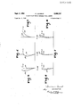
- Figures 3, 4 and 5 show the curves of spherical aberration and of aberration of the sines of known object-glasses.
- Figures 6, 7 and 8 show the corresponding curves of the object-glass in accordance with the invention. 1
- Figures 9, 10 and 11 show the curves of chromatic aberration of known object-glasses.
- Figures 12, 13 and 14 show the corresponding curves of the object-glass in accordance with the invention.
- the object-glass made in accordance with the invention comprises three lenses which form a front group A and a rear group B separated by an air space e: (of a variable thickness).
- the front group A comprises a convergent front lens I and a divergent lens formed of two glasses II. III.
- the total power of the front group is positive.
- e rear ro p B is formed of a single lens .which comprises two glasses 1V, V and has a total convergent power.
- Each of the groups A and B can be compared with a simple convergent lens and the resulting focal length of the whole unit can be calculated by applying the typical formula:
- n and I are the focal lengths of each of the groups and e: the interstice.
- the lens, the radii R, the thicknesses 1 of the lenses and-the spacings e are numbered in the direction of the incident light.
- the second column of the table indicates the refractive index for the line D and the third column indicates the in)dex of Abbe or dispersion coeflicient (V) or (nu).
- the radii have the sign for the interfaces the convexity of which is orientated towards the incident light and the sign for the interfaces the concavity of which is orientated towards the incident light.
- the focal length varies from 100 to 149 as indicated by the curve 20 of Figure 2 where the abscissae 2
- Figures 3, 4 and 5 indicate the variations of the spherical aberration (in full lines) 25 and of the sines (in broken lines) 28 for an ordinary objectglass the focal length of which is 100, 120 and 140 respectively.
- Figures 6, 7 and 8 indicate the same variations for the object-glass in accordance with the invention the divergence e: of which is regulated to convenient values in order to obtain focal lengths of 100, 120 and 140 respectively corresponding to the focal lengths of the object-glasses characterized by Figures 3, 4 and 5.
- Figures 9, 10 and 11 indicate the variations of the chromatism of position (in full lines) and of the chromatism of magnitude (in broken-lines) calculated for the lines C, D and F for ordinary projection object-glasses of f/1.5 with the focal lengths 100, 120 and 140 respectively.
- Figures 12, 13 and 14 indicate the variations of the same aberrations in an object-glass in accordance with the invention for the same focal lengths.
- the curves of variation of the chromatic aberration of magnitude and of the chromatic aberration of position are not much vdifferent from one another which is not the case in object-glasses the correspondent curves of which are indicated in Figures 9, 10 and 11.
- the object-glasses in accordance with the in vention give good images on the whole extent of the variation of the focal length.
- a positive front group of a focal length f1 comprising a p sitive front lens and two cemented lenses forming a divergent meniscus of positive convexity, said two cemented lenses being disposed behind the said positive front lens and separated therefrom by an air space of constant dimensions
- a rear group of focal length I comprising two cemented lenses, with an air space e2 separating the said positive front group from the said rear group, said air space e: being adjustable between 0 and h to permit adjustment of the focal length F of the assembly according to the equation:
Description
SEARCH ROON p 9, 1952 F. LAURENT OBJECT-GLASS WITH A VARIABLE FOCAL LENGTH 3 Sheets-Shoot 1 Z J a? Filed Jan. 5, 1949 IN v E/v-roR Ar 'aR rveY StAHL'H HUUI.
Sept. 9, 1952 F. LAURENT OBJECT-GLASS WITH A VARIABLE FOCAL LENGTH 3 Sheets-Shoot 2 Filed Jan. 5, 1949 A. h 3: n v a PL X w MM wwi mf a; w x n; m 3 m 9% km 3 1 and 1 2: .m a main n Fri \M W \N NW \N a; Q &N w; m n: W\ w V m mnm DLHKLH HULL Sept. 9, 1952 F. LAURENT OBJECT-GLASS mm A VARIABLE FOCAL LENGTH 25 Sheets-Sheet 3 Filed Jan. 5, ,1949
Quin .us HZ U .10 I! a AT-rmvsy Patented Sept. 9, 1952 OBJECT-GLASS WITH A VARIABLE FOCAL LENGTH Francois Laurent, Paris, France, assignmto Etablissements Emel, Paris, France, a French company Application January 5, 1949, Serial No. 69,285 In France January it, 1948 1 Claim. 1
Object-glasses have been known already for a long time in which a variation of the focal length may be obtained by shifting one of the elements with respect to the others. Though a small variation of the spacing of the elements can determine a comparatively high variation of the focal length, said object-glasses are not entirely satisfactory owing to the fact that the corrections are insured in a convenient manner only for a single value of the spacing or for a small variation of this spacing.
The invention relates to an object-glass with a variable focal length characterized in that it comprises a positive front group formed of a positive front lens and a negative rear lens separated by a variable air space from a positive rear group, which forms an object-glass with a variable focal length which is well corrected for a considerable extent of the values of the focal length.
According to a form of execution the rear group is formed of a single lens which reduces the number of the air-glass interfaces.
Other features will appear in the course of the following description.
In the appended drawing given by way of example:
Figure 1 is a diagrammatical view showing an object-glass made in accordance with the invention.
Figure 2 is the curve of variation of the foca length as a function of the spacing between the front group and the rear group of the objectglass.
Figures 3, 4 and 5 show the curves of spherical aberration and of aberration of the sines of known object-glasses.
Figures 6, 7 and 8 show the corresponding curves of the object-glass in accordance with the invention. 1
Figures 9, 10 and 11 show the curves of chromatic aberration of known object-glasses.
Figures 12, 13 and 14 show the corresponding curves of the object-glass in accordance with the invention.
As shown in Figure 1 the object-glass made in accordance with the invention comprises three lenses which form a front group A and a rear group B separated by an air space e: (of a variable thickness).
The front group A comprises a convergent front lens I and a divergent lens formed of two glasses II. III. The total power of the front group is positive.
e rear ro p B is formed of a single lens .which comprises two glasses 1V, V and has a total convergent power.
Each of the groups A and B can be compared with a simple convergent lens and the resulting focal length of the whole unit can be calculated by applying the typical formula:
where F is the resulting focal length, n and I: are the focal lengths of each of the groups and e: the interstice.
When e: varies from 0 to 11 the resultant formula F varies from By way of example if f1=50 and j2=30, F varies from 18.77 to 50.
The following table indicates the construction data of an object-glass having a, variable focal length according to the invention. Of course, said values are indicated only by way of example.
The lens, the radii R, the thicknesses 1 of the lenses and-the spacings e are numbered in the direction of the incident light. The second column of the table indicates the refractive index for the line D and the third column indicates the in)dex of Abbe or dispersion coeflicient (V) or (nu The radii have the sign for the interfaces the convexity of which is orientated towards the incident light and the sign for the interfaces the concavity of which is orientated towards the incident light.
For the above mentioned example the focal length varies from 100 to 149 as indicated by the curve 20 of Figure 2 where the abscissae 2| represent the values of the divergence ea in millimetres and the ordinates 22 the corresponding values of the focal length in millimetres.
Figures 3, 4 and 5 indicate the variations of the spherical aberration (in full lines) 25 and of the sines (in broken lines) 28 for an ordinary objectglass the focal length of which is 100, 120 and 140 respectively.
Figures 6, 7 and 8 indicate the same variations for the object-glass in accordance with the invention the divergence e: of which is regulated to convenient values in order to obtain focal lengths of 100, 120 and 140 respectively corresponding to the focal lengths of the object-glasses characterized by Figures 3, 4 and 5.
It is to be noted that the variations of the spherical aberration and the sines are substantially less for the object-glass in accordance with the invention.
Figures 9, 10 and 11 indicate the variations of the chromatism of position (in full lines) and of the chromatism of magnitude (in broken-lines) calculated for the lines C, D and F for ordinary projection object-glasses of f/1.5 with the focal lengths 100, 120 and 140 respectively.
Figures 12, 13 and 14 indicate the variations of the same aberrations in an object-glass in accordance with the invention for the same focal lengths.
It is to be noted that in the object-glass in accordance with the invention the aberrations show only a small variation while in the known objectglasses these variations are comparatively important.
Furthermore, in the object-glass according to the invention the curves of variation of the chromatic aberration of magnitude and of the chromatic aberration of position are not much vdifferent from one another which is not the case in object-glasses the correspondent curves of which are indicated in Figures 9, 10 and 11.
It results from the comparison of the curves ofFigures 6, 7 and 8 with the curves of Figures 3, 4 and 5 and from the comparison of the curves of Figures 12, 13 and 14 with the curves of Figure 9, 10 and 11 that the variations of the corrections of an object-glass according to the invention are 4 substantially smaller than those of the known object-glasses. I
The object-glasses in accordance with the in vention give good images on the whole extent of the variation of the focal length.
Of course, the invention is not limited to the form of execution which has been described.
I claim:
In a variable focal length objective, a positive front group of a focal length f1 comprising a p sitive front lens and two cemented lenses forming a divergent meniscus of positive convexity, said two cemented lenses being disposed behind the said positive front lens and separated therefrom by an air space of constant dimensions, a rear group of focal length I: comprising two cemented lenses, with an air space e2 separating the said positive front group from the said rear group, said air space e: being adjustable between 0 and h to permit adjustment of the focal length F of the assembly according to the equation:
fiXfz ani-a whereby the focal length F varies between the value FRANCOIS LAURENT.
REFERENCES crrnn The following references are of record'in the flle of this patent:
UNITED STATES PATENTS Number Name Date 1,860,575 Gehrke May 31, 1932 1,880,394 Altmann Oct. 4, 1932 1,927,925 Dieterich Sept. 26, 1933 1,988,390 Naumann Jan. 15, 1935 2,042,815 White June 2, 1936 2,245,241 Wood June 10, 1941 2,271,227 Lee Jan. 27, 1942 FOREIGN PATENTS Number Country Date 26,085 France Apr. 10, 1923 (1st addition to 517,014) 878,741 France Oct. 26, 1942
Applications Claiming Priority (1)
| Application Number | Priority Date | Filing Date | Title |
|---|---|---|---|
| FR2609727X | 1948-01-10 |
Publications (1)
| Publication Number | Publication Date |
|---|---|
| US2609727A true US2609727A (en) | 1952-09-09 |
Family
ID=9687133
Family Applications (1)
| Application Number | Title | Priority Date | Filing Date |
|---|---|---|---|
| US69285A Expired - Lifetime US2609727A (en) | 1948-01-10 | 1949-01-05 | Object-glass with a variable focal length |
Country Status (1)
| Country | Link |
|---|---|
| US (1) | US2609727A (en) |
Cited By (1)
| Publication number | Priority date | Publication date | Assignee | Title |
|---|---|---|---|---|
| DE1236817B (en) * | 1961-02-28 | 1967-03-16 | Nippon Kogaku Kk | Pancratic lens |
Citations (9)
| Publication number | Priority date | Publication date | Assignee | Title |
|---|---|---|---|---|
| FR517014A (en) * | 1920-06-11 | 1921-04-29 | Auguste Jean Baptiste Tauleign | Lens intended for projection and giving maximum illumination |
| US1860575A (en) * | 1928-04-04 | 1932-05-31 | Agfa Ansco Corp | Photographic objective |
| US1880394A (en) * | 1930-12-11 | 1932-10-04 | Eastman Kodak Co | Photographic objective |
| US1927925A (en) * | 1927-08-30 | 1933-09-26 | Ludwig M Dieterich | Photographic production |
| US1988390A (en) * | 1931-03-12 | 1935-01-15 | Emil Busch Ag | Change-focus objective |
| US2042815A (en) * | 1933-06-27 | 1936-06-02 | Lester Hofheimer | Display apparatus and optical system |
| US2245241A (en) * | 1939-01-12 | 1941-06-10 | Eastman Kodak Co | Lens mount and method of assembling the same |
| US2271227A (en) * | 1940-02-14 | 1942-01-27 | Eastman Kodak Co | Lens mount |
| FR878741A (en) * | 1941-09-19 | 1943-01-28 | Adjustable protection lens |
-
1949
- 1949-01-05 US US69285A patent/US2609727A/en not_active Expired - Lifetime
Patent Citations (10)
| Publication number | Priority date | Publication date | Assignee | Title |
|---|---|---|---|---|
| FR517014A (en) * | 1920-06-11 | 1921-04-29 | Auguste Jean Baptiste Tauleign | Lens intended for projection and giving maximum illumination |
| FR26085E (en) * | 1920-06-11 | 1923-07-30 | Lens intended for projection and giving maximum illumination | |
| US1927925A (en) * | 1927-08-30 | 1933-09-26 | Ludwig M Dieterich | Photographic production |
| US1860575A (en) * | 1928-04-04 | 1932-05-31 | Agfa Ansco Corp | Photographic objective |
| US1880394A (en) * | 1930-12-11 | 1932-10-04 | Eastman Kodak Co | Photographic objective |
| US1988390A (en) * | 1931-03-12 | 1935-01-15 | Emil Busch Ag | Change-focus objective |
| US2042815A (en) * | 1933-06-27 | 1936-06-02 | Lester Hofheimer | Display apparatus and optical system |
| US2245241A (en) * | 1939-01-12 | 1941-06-10 | Eastman Kodak Co | Lens mount and method of assembling the same |
| US2271227A (en) * | 1940-02-14 | 1942-01-27 | Eastman Kodak Co | Lens mount |
| FR878741A (en) * | 1941-09-19 | 1943-01-28 | Adjustable protection lens |
Cited By (1)
| Publication number | Priority date | Publication date | Assignee | Title |
|---|---|---|---|---|
| DE1236817B (en) * | 1961-02-28 | 1967-03-16 | Nippon Kogaku Kk | Pancratic lens |
Similar Documents
| Publication | Publication Date | Title |
|---|---|---|
| US3948584A (en) | High speed lens having short back focus and compact rear member | |
| US2324057A (en) | Lens attachment | |
| US2354503A (en) | Optical objective of the telephoto type | |
| US2440088A (en) | Optical lens system | |
| US2752821A (en) | Wide angle anamorphotic attachments for optical objectives | |
| US2735339A (en) | Yoshikazu doi | |
| US1792917A (en) | Photographic objective | |
| US2380210A (en) | Telecentric lens system | |
| US2609727A (en) | Object-glass with a variable focal length | |
| US2164028A (en) | Photographic objective | |
| US2324081A (en) | Microscope objective | |
| US3669527A (en) | Wide angle photographic objective having nonspherical surfaces | |
| US2855824A (en) | Large aperture lens for lenticular film photography | |
| US2405301A (en) | Optical system | |
| US1967836A (en) | Photographic lens | |
| US2417330A (en) | Lens for optical purposes | |
| US2186622A (en) | Lens system | |
| US2724994A (en) | Photographic objective comprising four meniscus shaped air spaced components | |
| US4362366A (en) | Focal length extender | |
| US2327759A (en) | Telephoto objective | |
| US2721501A (en) | Three-component objective | |
| US1945951A (en) | Afocal objectives | |
| US2789463A (en) | Focal lens system for attaching to photographic objectives | |
| US2725789A (en) | Wide angle photographic objective | |
| US2502544A (en) | Optical objective for profile projections |