US2586666A - Sound-on-film recording and reproducing machine - Google Patents
Sound-on-film recording and reproducing machine Download PDFInfo
- Publication number
- US2586666A US2586666A US534054A US53405444A US2586666A US 2586666 A US2586666 A US 2586666A US 534054 A US534054 A US 534054A US 53405444 A US53405444 A US 53405444A US 2586666 A US2586666 A US 2586666A
- Authority
- US
- United States
- Prior art keywords
- film
- sound
- shaft
- track
- stylus
- Prior art date
- Legal status (The legal status is an assumption and is not a legal conclusion. Google has not performed a legal analysis and makes no representation as to the accuracy of the status listed.)
- Expired - Lifetime
Links
Images


Classifications
-
- G—PHYSICS
- G11—INFORMATION STORAGE
- G11B—INFORMATION STORAGE BASED ON RELATIVE MOVEMENT BETWEEN RECORD CARRIER AND TRANSDUCER
- G11B25/00—Apparatus characterised by the shape of record carrier employed but not specific to the method of recording or reproducing, e.g. dictating apparatus; Combinations of such apparatus
- G11B25/06—Apparatus characterised by the shape of record carrier employed but not specific to the method of recording or reproducing, e.g. dictating apparatus; Combinations of such apparatus using web-form record carriers, e.g. tape
Definitions
- This invention relates to a machine for recording sound vibrations on a strip of endless film for reproduction purposes and also for reproducing sound from such a film and particularly to a machine of the multi-track type.
- Another object is to adjust the stylus of the sound unit upon the film.
- Another object is to so loop the endless film upon its support that both surfaces of the film are utilized automatically for cutting grooves thereon and for reproducing therefrom.
- Another object is to drive the film by pressure friction thereby eliminating the need of sprocket Wheels and perforated film tape, and eliminating noise, providing a steady constant smooth flow of film, preventing slipping of the film and preserving the film fresh and clean.
- Another object is to provide a carrier or support for a reel or loop of endless film provided with means for adjusting the tension of the film lengthwise and permits ready mounting and'demounting of the film thereon in looped formation.
- Another object is to provide such a reel holder with improved film guiding means thereby eliminating the necessity of reel sides customarily used to guide the film and thus eliminating all strain and friction during travel.
- Another object is to provide a carrier or support for the reel whereby the film is visible throughits entire path of travel and is readily accessible for any desired purpose.
- Another object is to provide means for bypassing the sound box to utilize the apparatus for public address purposes.
- Another object is to provide means for "reproducing the recorded matter for an indefinite period of time.
- Another object is to provide sucha film holder that is simple and rugged in construction and inexpensive -to manufacture.
- Another object is to releasably support "the layer of film in operative position adjacent the stylus.
- Another object is to provide means for stopping the film drive instantaneously, without stopping the motor.
- Another object is to regulate the speed of the film drive.
- Another object is to save film by utilizing both 1 Claim. (Cl. 274-11;
- a track iscut upon one surface of the endless film for its'entire length and then automatically the opposite surface of the film is presented 'to the cutting stylus and a track'iscut upon said opposite surface for the entire length of the film when the first named surface is again presented to the stylusfor cutting asecond track thereon forthe entire length of the film and so on until tracks are out upon both surfaces of the film across the width of each or any portion of such width desired.
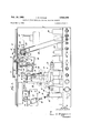
- Fig. 1 is a front view of my improved machine.
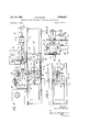
- Fig. 2 is an enlarged rear view thereof.
- Fig. 3 is an enlarged top plan view.
- Fig. 4 is an enlarged top plan view of a fragment of the machine showing the sound unit moved to a position different from that shown in Fig. 3.
- Fig. 5 is an enlarged sectional view taken on the plane of the line 55 of Fig. 3.
- Fig. 6 is anenlarged fragmentary View showing the pressure roller moving mechanism and the sound unit moving mechanism with some of the parts being missing.
- Fig. '7 is a view similar to Fig. 6 but showing the parts in moved position.
- Fig. 8 is an enlarged perspective view of an endless film used with my improved machine.
- Fig. 9 is an enlarged view showing a fragment of the film to show the opaque section for operating the photo-electric cell.
- Fig. 10 is a diagrammatic view showing the circuit for the photo-electric cell.
- My improved machine may be of the stationary or portable type and comprises'a base [0 with a front wall I l. Supported on said wall forwardly thereof by means of cross bars I2 is a panel or instrument board [-3 extending from the top a short distance therebelow.
- the machine is electrically operated and is adapted to be connected to a sourceof electromotive power, such as the .housesupply.
- a sourceof electromotive power such as the .housesupply.
- Current is brought to a motor I4 supported by brackets IE on the rear of the wall II.
- the motor shaft l6 drives a drive roller I l at the front of the wall.
- the film used with my machine is of the endless or continuous type and is formed of any suitable film stock, such as cellulose acetate which is transparent and is neither coated nor perforated.- It consists of a reel or loop [8 including a plurality of layers.
- the reel is sup- 3 ported in looped formation on a disk l9 rotatably mounted on a plate fastened to the front of the wall at one of the lower corners thereof.
- This plate is mounted at an angle to the vertical so that its lower portion projects outwardly of the wall and the disc is mounted truly parallel with said plate so that both the plate and disc are tilted relative to the wall leaving a clearance at the bottom to permit the looped reel to be mounted over the disc.
- a portion of the reel is looped over an idler roller 2
- the shaft 23 moves in an arcuate slot 25 formed in the plate against the action of a spring 21.
- the innermost layer or convolution 28 of the film reel or winding leaves the reel at the point of the idler roller 2! and passes upwardly over an idler roller 29 on the front of the wall fl and upwardly over a base member or anvil 30 on the front of the wall II. From the base, the layer 28 of film passes downwardly to and over the drive roller I!
- Plate 20 has stud members 32 and 33 at each of the lower corners for supporting a plate (not shown) in the front thereof for keeping the reel intact and in position.
- a finger piece 34 may be mounted on the plate 20 so as to extend across the side edge of the reel and layer 28 to prevent such parts from becoming displaced laterally.
- a vertically disposed bar 35 is mounted at the rear of the wall I! on a stub shaft 36 which is rockably mounted in the wall H and extends through an opening in said Wall to the front thereof.
- the front end of this shaft 36 supports fixedly an arm 31 and carried on the free end of arm 31 is a presser roller 38 which is adapted to be swung into and out of engagement with the drive roller [1.
- a bracket 39 fixed to the rear of wall II and to one side of the bar 35 supports a magnet 45.
- of the magnet is formed with a spring pressed pivoted nose 42 and the opposite end of the core has a lug 43 fixed thereto.
- the nose 42 is adapted to engage and to interlock with the edge wall 45 of a slot 46 formed in a shelf 41 on the bracket 39 for holding the core in extended position.
- Another magnet 48 is mounted on the bracket 33 below the slot in the shelf 4! and is so positioned that one end 49 of its core 56 is adapted to move into and out of engagement with the nose 42 of core 4
- has one end fastened to the opposite end of core 50 and has its other end secured to a fixed bracket 52.
- a bracket 53 fastened to the wall on the other side of bar 35 is another magnet 54.
- core 55 of this magnet has a plate 56 fastened to one end thereof adapted to be moved into and out of engagement with the teeth of a toothed wheel 51 for a purpose later to be described.
- the other end of the core mounts a lug 58 for connecting said end to a coiled spring 59, the other end of which spring is fastened to a lug 60 on the bar 35 adjacent its top end.
- the plate member 56 moves in and is guided by the walls of a slot 6
- the sound unit of my improved machine comprises a sound head or box 63 containing the ordinary electro-magnetic mechanism for recording and reproducing sound and having a detachable stylus 64.
- the sound box is mounted for step-by-step movement along a screw threaded shaft 65 extending across and journalled in the wall H and instrument board l3 adjacent the top thereof.
- the sound box 63 is secured to one side of a plate 65 having a central opening .61 near its top and with spaced bearing lugs 68 on its top edge.
- On plate 66 on the side opposite the sound box is an arm member 69 formed with an internally screw threaded sleeve bearing member '10, the threads of which engage the external threads on the shaft 65.
- a vertical bar or casting H is positioned alongside of plate 66 and is formed with an opening through which the threaded sleeve member 10 loosely extends.
- a notched rod 12 is supported in an opening in this casting near the top end.
- This rod has an elongated horizontal portion as seen in Fig. l, a vertical portion 13 extending downwardly along the casting ll which terminates in a slightly curved horizontal portion 14 extending in a direction opposite to the direction of the elongated horizontal portion.
- This rod l2 extends through an opening in the plate 66 and adjustably supports a weight I5 on its elongated horizontal portion. The combined weight of the rod 72, weight 15 and casting H is transmitted to the sound box or head 63 through the arm 69 of plate 66.
- the sound box 63 and plate 56 move hingedly as a unit relative to the casting H and the extent of the swinging movement of said unit may be regulated by a notched rod 1'! hingedly supported on the top of the plate 65 by the lugs 68, and a weight 18 adjustably supported on said rod 17 for holding the moved unit in adjusted position.
- a knob or handle 19 is fastened to the outer end of the shaft 65 for manually rotating the same.
- An important feature of my present invention is mechanism for automatically moving the sound box 63 step-by-step, along the shaft 65, and track-by-track across the film.
- This mechanism includes a photo-cell indicated generally at 83 and an agitating light indicated generally at 84, in Fig. l, and shown diagrammatically in Fig. 10. Any approved type of photo-electric cell sensitive to light may be used.
- the cell and light are positioned adjacent the path of movement of the film but oppositely disposed so that the beam from the light will agitate the cell and so that said film will pass between the light and cell.
- the film is provided at a point along its length with an opaque section 85 extending from edge to edge of the film. During the travel of the film, the opaque section will pass between be understood.
- the photo electric cell is in circuit withthe magnet 54 and when the beam from light 84 is interrupted the cell becomes active closing the circuit through magnet 54 and thus energizing the same.
- the core 55 moves outwardly forcin the plate 56 at its end against one of the teeth of wheel 51, which wheel is operatively connected to shaft 65 mounting the sound box 63. Movement of the wheel one notch will rotate the screw threaded shaft 65 one notch thereby moving the sound box one step along the shaft and move the stylus from one track to the next track upon the film as will be understood.
- the core 55 of magnet 54 is returned to normal inoperative position by the coiled spring 59.
- Means may be provided for regulating the speed of the drive for the film.
- An ordinary governor ball 86 is adapted to be engaged by a breaking arm 81; actuated by a pin 88 moved by an arm 89 connected by a link 90 to another arm 9
- I also provide mechanism for balancing the movement of the toothed wheel 51 and operating shaft 65 for the sound unit.
- This mechanism includes a weighted bar member 94 pivotally mounted at one end on a stub shaft 95 extending rearwardly from the wall II.
- the bar carries a pin 96 midway its length and extending laterally thereof, which pin is adapted to engage in the grooves on the periphery of a grooved wheel 91 fixed on the extension of shaft 65 mounting the toothed wheel 51.
- the other end of the bar is fastened to one end of a spring 98, the other end of which spring is fastened to the bracket 53 supporting the magnet 54.
- Means may also be provided for indicating the position of the stylus on the film.
- a spur gear 99 is fastened to the extension of shaft 65 mounting the toothed wheel 51, just inside of the instrument board I3, which gear is in continuous mesh with the toothed periphery of a disc dial member I 90 mounted rotatably on a stub shaft on the instrument board.
- the dial I90 carries indicia on its surface such as the track number or the section of a particular track, which indicia is seen through a window IIlI formed in the instrument board.
- the dial I99 and toothed wheel 51 are synchronized and corelated so that the track on which the stylus is working appears in the window.
- the amplifyin apparatus for amplifying the sound reproduced by the machine is carried by a chassis I92 but forms no part of the present invention.
- This apparatus includes the various tubes I03 for recording, reproducing or play-back and public address systems, and the switch controls for operating such mechanism.
- the master switch control for the amplifying apparatus is actuated by an endless chain I04 extending from and moved by a sprocket wheel I05 fixed on the inner end of rockable shaft 89 mounting the cam 8
- the inner end of the shaft 80 is supported by a bushing I06 on a bracket I91 and fixed on the bushing I96 is a disc member I98 having spaced protuberances I09 on its surface.
- a 111g member III] fixed on the shaft adjacent the disc member has an eyelet portion III adapted to --wipe .over
- the knob 82 on shaft 80 is turned to the position R for recording.
- the cam BI is free of the curved portion I4 of the rod 12 so that the combinedweight of the sound box 63, plate 66, casting II and rod I2 with its weighted member I5 is impressed upon the stylus 64 so that it will have sufiicient weight to cut a track on the film surface for its entire length for recording purposes.
- Turning the shaft 89 to recording position also moves the chain I94 to bring the amplifying apparatus into circuit with the broadcasting device for reproducing purposes.
- a master switch H2 is turned for closin the electrical circuits for the various mechanisms, at which time a pilot light I I2 lights up to indicate that recording is in progress.
- a switch H3 is turned to bring either-the microphone, indicated by the pilot light I I4, or the telephone, indicated by the pilot light II5, into circuit with the apparatus.
- Switch H6 is turned to start the motor I4 for driving the drive roller H.
- the speed of the motor may be regulated by turning the knob 93 to F for fast or S for slow.
- the film being endless will be cut for its entire lengthparallel to its edges and will travel around its circuitous path until the opaque section thereof comes between the light 84 and photo cell 83 cutting off the beam from said light and activating the cell.
- this cell When this cell becomes activated, it closes a circuit including the magnet 54 and when this magnet becomesenergized its core moves outwardly carrying the plate 56 into engagement with a toothof the toothed Wheel 51 forcing said wheel around one notch and thereby rotating the screw threaded shaft 65 and moving the sound unit including the sound box and stylus one step across the film to position the stylus for cutting another track thereon.
- the core of the magnet 54 is immediately returned to its normal inoperative position by the spring 59. There is no stopping of the movement of the film on other parts during thismovement of the stylus from track to track.
- a switch button I I8 is moved to close a circuit including the magnet 48 whereby said magnet becomes energized when its core 50 will move into engagement with the nose latching member 42 releasing said latch permittingthe spring 59- to pull the arm 35 on its pivot for swinging the presser roller 38 away from the drive roller H at which instant the movement of the film as well as the recording stops.
- the stoppage is thus accomplished instantaneously so that the sound can be stopped even after a syllable and started at the same point.
- the-knob ,82 is turned tothe position P called the Play-Back position. This moves the cam 8
- the weight 78 on the rod TI may be moved along said rod to the side of the pivotal point of the sound unit to thereby offset the weight of said sound unit and connected parts.
- the weight on the rod 12 may be moved toward the said pivotal point to lessen the weight. This relieves the pressure on the stylus but sufiicient pressure remains to keep the stylus in engagement with the walls of the out groove or track for reproducing the sound.
- Movement of the shaft 80 to P" position turns off the pilot light H2 and simultaneously, by means of the chain 104, closes the circuit through the amplifying apparatus for Play-Back purposes only.
- the sound is reproduced and sent through either a. loud speaker H9 built in the machine and operatively connected to the sound box and amplifying apparatus, or a loud speaker situated remote from the machine, either of which speakers may be placed in circuit by a switch member I20.
- a pilot light 12! may be used to indicate that the loud speaker H9 is in circuit or a pilot light I22 may be used to indicate that the remote loud speaker is in circuit.
- the pilot lights may be of the same or different colors.
- the knob 82 is turned clockwise, as seen in Fig. 1, to the position PA, called Public Address, so as to bring the cam 8
- PA Public Address
- the film can be reversed in direction or it can be moved ahead for necessary attention.
- any sound go-' ing into the microphone or telephone passes directly into and through the amplifier apparatus where it is amplified for public address and sent through the loud speaker.
- the film is wound in the form of a reel or loop with a number of layers or convolutions and with one layer extending loosely from the remaining layers.
- the looped layers are positioned around the periphery of thudisc l9 and around the peripheries of the rollers 2i and 22 which can readily be done by moving the roller 22 inwardly and after it is encircled by the looped layers permitting it to be pulled outwardly again by the spring 21.
- the loosely extending portion of the layer is looped around the rollers 21, 29, base and rollers 11 and 3
- Another important feature of my invention is the means for utilizing both surfaces of the film for recording and reproducing purposes.
- a number of sound tracks can be impressed on both sides or surfaces, for example, forty on each surface.
- I accomplish this by forming a twist, as indicated at 28 in the endless or continuous reel as shown in the reel of Fig. 8.
- the film reel shown on the machine of Fig. 1 is not formed with the twist.
- the reel mounts the reel on its support so that the twist occurs between the rollers 3
- first one surface for example, the surface indicated at A is presented to the stylus for the entire length of the film reel for cutting a track thereupon for the entire length, and then upon completion of a complete rotation of the entire length of film, the surface opposite to said surface A, or the surface indicated at B will be presented to the stylus for cutting a track upon said surface B for the entire length of the film reel, and when the end of said length is reached, the first-named surface A will again be presented to the stylus for cutting another track thereupon for its entire length, and soon until the stylus has traversed across the width of the film.
- the tracks on the opposite surfaces will be alternately arranged. For example, if the tracks are to be cut from right to left of the film as viewed in Fig. 9, the first track on the first surface presented to the stylus, say surface A, will be adjacent the right edge. Then a track is cut on the opposite surface B at a point one space toward the left from the track on surface A. Next a second track is cut on surface A at a point to the left of the track on surface B and so on until the stylus reaches the left hand edge of the film. This presentation of the opposite surfaces of the film to the stylus is done automatically without stoppage of the travel of the film.
- the film stock of commerce is of suflicient depth to permit this cutting of tracks upon both surfaces.
- the photo-electric cell may be cut out of the system or made ineffectual in which case the stylus will remain in the same track and will continue to reproduce the recorded matter insaid track for an indefinite period of time which is invaluable for advertising purposes.
- a device such as a Neon flasher may be connected to the system for indicating the level of the sound being recorded or broadcasted.
- mechanism may be operatively connected to the system for automatically controlling the volume or for boosting the incoming signals or for limiting the outgoing signals.
- the various switches provided may be controlled remotely if desired and any number of loud speakers or microphones and any type of microphone may be used.
- an endless transparent traveling film having an opaque section, means for moving said film, an externally screw-threaded shaft, a sound unit including a sound box with a stylus adapted to engage said film, a plate fixed to said box, a tubular sleeve member on said plate having internal screw threads adapted to coact with the threads on said shaft, magnetically operated means for rotating said shaft including a toothed wheel on the end of said shaft, a magnet adjacent said wheel with its core movable into and out of engagement with the teeth of said wheel and a photoelectric cell controlled by the passag'ebf;; the opaque section of the endless film for abfiiating said magnet and me'iis for balancing the; movement of said shaft comprising a grooveid wheel fixed on said shaift fqdjacent said toothed wheel and a spring pressed weighted armQieldingly engaging said g ob'i ed wheel for balan'ii lg the movement
Description
Feb. 19, 1952 J. M. KUHLIK 2,586,
SOUND-ON-FILM RECORDING AND REPRODUC'ING MACHINE Filed May 4, 1944 I 4 Sheets-Sheet l 2 i5 4 INVEN TOR.
1% facofiL/(dh/z'k fITTOHNEY J. M. KUHLIK Feb. 19, 1952 SOUND-0N-FILM RECORDING AND REPRODUCING MACHINE Filed May 4, 1944 4 Sheets-Sheet 2 EMS.
Feb. 19, 1952 J. M. KUHLIK 2,586,6
SOUND-ON-FILM RECORDING AND REPRODUCING MACHINE Filed May 4, 1944 4 Sheets-Sheet 3 Q INVENTOR. JavoZ/L/(a/Hz'k BY W S.
J. M. KUHLIK Feb. 19, 1952 SOUND-ON-FILM RECORDING AND REPRODUCING MACHINE Filed May 4, 1944 4 Sheets-Sheet 4 IN VEN TOR.
Jacob M. K4111 71k Patented Feb. 19, 1952 n OFFICE SOUND-ON-FILM RECORDING AND .REPRODUCINGiMA'CHINE Jacob M. tKuhlik, Brooklyn, N; Y., assignor. to Hattie 3B. Kuhlik, Sea:1Gate,;N. Y.
Application May 4, 1944,;ScrialjN0. 53.4;054
This invention relates to a machine for recording sound vibrations on a strip of endless film for reproduction purposes and also for reproducing sound from such a film and particularly to a machine of the multi-track type.
It is a primary object of my invention to provide in a multi-track, sound-on-film recorder and/or reproducer, automatic means for relatively shifting the recorder and reproducer from track to track of the film.
Another object is to adjust the stylus of the sound unit upon the film.
Another object is to so loop the endless film upon its support that both surfaces of the film are utilized automatically for cutting grooves thereon and for reproducing therefrom.
Another object is to drive the film by pressure friction thereby eliminating the need of sprocket Wheels and perforated film tape, and eliminating noise, providing a steady constant smooth flow of film, preventing slipping of the film and preserving the film fresh and clean.
Another object is to provide a carrier or support for a reel or loop of endless film provided with means for adjusting the tension of the film lengthwise and permits ready mounting and'demounting of the film thereon in looped formation.
Another object is to provide such a reel holder with improved film guiding means thereby eliminating the necessity of reel sides customarily used to guide the film and thus eliminating all strain and friction during travel.
Another object is to provide a carrier or support for the reel whereby the film is visible throughits entire path of travel and is readily accessible for any desired purpose.
Another object is to provide means for bypassing the sound box to utilize the apparatus for public address purposes.
Another object is to provide means for "reproducing the recorded matter for an indefinite period of time.
Another object is to provide sucha film holder that is simple and rugged in construction and inexpensive -to manufacture.
Another object is to releasably support "the layer of film in operative position adjacent the stylus.
Another object is to provide means for stopping the film drive instantaneously, without stopping the motor.
Another object is to regulate the speed of the film drive.
Another object is to save film by utilizing both 1 Claim. (Cl. 274-11;
surfaces of the film for cutting sound grooves thereon.
According to another object of my invention a track iscut upon one surface of the endless film for its'entire length and then automatically the opposite surface of the film is presented 'to the cutting stylus and a track'iscut upon said opposite surface for the entire length of the film when the first named surface is again presented to the stylusfor cutting asecond track thereon forthe entire length of the film and so on until tracks are out upon both surfaces of the film across the width of each or any portion of such width desired.
Fig. 1 is a front view of my improved machine.
Fig. 2 is an enlarged rear view thereof.
Fig. 3 is an enlarged top plan view.
Fig. 4 is an enlarged top plan view of a fragment of the machine showing the sound unit moved to a position different from that shown in Fig. 3.
Fig. 5 is an enlarged sectional view taken on the plane of the line 55 of Fig. 3.
Fig. 6 is anenlarged fragmentary View showing the pressure roller moving mechanism and the sound unit moving mechanism with some of the parts being missing.
Fig. '7 is a view similar to Fig. 6 but showing the parts in moved position.
Fig. 8is an enlarged perspective view of an endless film used with my improved machine.
Fig. 9is an enlarged view showing a fragment of the film to show the opaque section for operating the photo-electric cell.
Fig. 10 is a diagrammatic view showing the circuit for the photo-electric cell.
My improved machine may be of the stationary or portable type and comprises'a base [0 with a front wall I l. Supported on said wall forwardly thereof by means of cross bars I2 is a panel or instrument board [-3 extending from the top a short distance therebelow.
The machine is electrically operated and is adapted to be connected to a sourceof electromotive power, such as the .housesupply. Current is brought to a motor I4 supported by brackets IE on the rear of the wall II. The motor shaft l6 drives a drive roller I l at the front of the wall.
The film used with my machine is of the endless or continuous type and is formed of any suitable film stock, such as cellulose acetate which is transparent and is neither coated nor perforated.- It consists of a reel or loop [8 including a plurality of layers. The reelis sup- 3 ported in looped formation on a disk l9 rotatably mounted on a plate fastened to the front of the wall at one of the lower corners thereof. This plate is mounted at an angle to the vertical so that its lower portion projects outwardly of the wall and the disc is mounted truly parallel with said plate so that both the plate and disc are tilted relative to the wall leaving a clearance at the bottom to permit the looped reel to be mounted over the disc. A portion of the reel is looped over an idler roller 2| on the plate and over and adjustable tensioning roller 22 which is rotatably mounted on a stub shaft 23 carried at the free top end of an arm 24 pivoted at 25, at the rear of the plate. The shaft 23 moves in an arcuate slot 25 formed in the plate against the action of a spring 21. The innermost layer or convolution 28 of the film reel or winding leaves the reel at the point of the idler roller 2! and passes upwardly over an idler roller 29 on the front of the wall fl and upwardly over a base member or anvil 30 on the front of the wall II. From the base, the layer 28 of film passes downwardly to and over the drive roller I! only lightly engaging the surface of said drive roller and from there it returns to roller 2| and back to the reel to become the outermost layer or convolution of the reel as will be seen from Fig. 1. Plate 20 has stud members 32 and 33 at each of the lower corners for supporting a plate (not shown) in the front thereof for keeping the reel intact and in position.
A finger piece 34 may be mounted on the plate 20 so as to extend across the side edge of the reel and layer 28 to prevent such parts from becoming displaced laterally.
Referring to Figs. 6 and 7, a vertically disposed bar 35 is mounted at the rear of the wall I! on a stub shaft 36 which is rockably mounted in the wall H and extends through an opening in said Wall to the front thereof. The front end of this shaft 36 supports fixedly an arm 31 and carried on the free end of arm 31 is a presser roller 38 which is adapted to be swung into and out of engagement with the drive roller [1.
A bracket 39 fixed to the rear of wall II and to one side of the bar 35 supports a magnet 45. One end of the core 4| of the magnet is formed with a spring pressed pivoted nose 42 and the opposite end of the core has a lug 43 fixed thereto. The nose 42 is adapted to engage and to interlock with the edge wall 45 of a slot 46 formed in a shelf 41 on the bracket 39 for holding the core in extended position.
Another magnet 48 is mounted on the bracket 33 below the slot in the shelf 4! and is so positioned that one end 49 of its core 56 is adapted to move into and out of engagement with the nose 42 of core 4| for forcing said nose out of interlocking engagement with the edge wall 45' of the shelf. A coiled spring 5| has one end fastened to the opposite end of core 50 and has its other end secured to a fixed bracket 52.
On a bracket 53 fastened to the wall on the other side of bar 35 is another magnet 54. core 55 of this magnet has a plate 56 fastened to one end thereof adapted to be moved into and out of engagement with the teeth of a toothed wheel 51 for a purpose later to be described. The other end of the core mounts a lug 58 for connecting said end to a coiled spring 59, the other end of which spring is fastened to a lug 60 on the bar 35 adjacent its top end. The plate member 56 moves in and is guided by the walls of a slot 6| formed in the shelf 62 of the bracket 53.
The
Referring to Figs. 3, 4 and 5, the sound unit of my improved machine comprises a sound head or box 63 containing the ordinary electro-magnetic mechanism for recording and reproducing sound and having a detachable stylus 64. The sound box is mounted for step-by-step movement along a screw threaded shaft 65 extending across and journalled in the wall H and instrument board l3 adjacent the top thereof. The sound box 63 is secured to one side of a plate 65 having a central opening .61 near its top and with spaced bearing lugs 68 on its top edge. On plate 66 on the side opposite the sound box is an arm member 69 formed with an internally screw threaded sleeve bearing member '10, the threads of which engage the external threads on the shaft 65. A vertical bar or casting H is positioned alongside of plate 66 and is formed with an opening through which the threaded sleeve member 10 loosely extends. A notched rod 12 is supported in an opening in this casting near the top end. This rod has an elongated horizontal portion as seen in Fig. l, a vertical portion 13 extending downwardly along the casting ll which terminates in a slightly curved horizontal portion 14 extending in a direction opposite to the direction of the elongated horizontal portion. This rod l2 extends through an opening in the plate 66 and adjustably supports a weight I5 on its elongated horizontal portion. The combined weight of the rod 72, weight 15 and casting H is transmitted to the sound box or head 63 through the arm 69 of plate 66.
The sound box 63 and plate 56 move hingedly as a unit relative to the casting H and the extent of the swinging movement of said unit may be regulated by a notched rod 1'! hingedly supported on the top of the plate 65 by the lugs 68, and a weight 18 adjustably supported on said rod 17 for holding the moved unit in adjusted position.
A knob or handle 19 is fastened to the outer end of the shaft 65 for manually rotating the same.
Rockably supported by the Wall H and instrument board l3 and extending therebetween in parallel relationship to the shaft 65 is a shaft and fixed on shaft 80 is a cam member 31 with a flaring edge adapted to be moved into and out of engagement with the curved portion 74 of rod 12. Then moved downwardly into engagement with this rod 12, as viewed in Fig. 1, because ofthe rigid connection between said rod and the casting 1 I plate 66 and sound box 63, said casting, plate and sound box are tilted upwardly as a unit carrying the stylus 54 of the sound box off of the film.
An important feature of my present invention is mechanism for automatically moving the sound box 63 step-by-step, along the shaft 65, and track-by-track across the film. This mechanism includes a photo-cell indicated generally at 83 and an agitating light indicated generally at 84, in Fig. l, and shown diagrammatically in Fig. 10. Any approved type of photo-electric cell sensitive to light may be used. The cell and light are positioned adjacent the path of movement of the film but oppositely disposed so that the beam from the light will agitate the cell and so that said film will pass between the light and cell. The film is provided at a point along its length with an opaque section 85 extending from edge to edge of the film. During the travel of the film, the opaque section will pass between be understood.
. y The photo electric cell is in circuit withthe magnet 54 and when the beam from light 84 is interrupted the cell becomes active closing the circuit through magnet 54 and thus energizing the same. When energized, the core 55 moves outwardly forcin the plate 56 at its end against one of the teeth of wheel 51, which wheel is operatively connected to shaft 65 mounting the sound box 63. Movement of the wheel one notch will rotate the screw threaded shaft 65 one notch thereby moving the sound box one step along the shaft and move the stylus from one track to the next track upon the film as will be understood. The core 55 of magnet 54 is returned to normal inoperative position by the coiled spring 59.
Means may be provided for regulating the speed of the drive for the film. An ordinary governor ball 86 is adapted to be engaged by a breaking arm 81; actuated by a pin 88 moved by an arm 89 connected by a link 90 to another arm 9| fastened to a movable shaft 92 extending from the rear of wall II to the front of the instrument board I3 where it can be manually operated by a knob 93 for fast or slow movement as desired.
I also provide mechanism for balancing the movement of the toothed wheel 51 and operating shaft 65 for the sound unit. This mechanism includes a weighted bar member 94 pivotally mounted at one end on a stub shaft 95 extending rearwardly from the wall II. The bar carries a pin 96 midway its length and extending laterally thereof, which pin is adapted to engage in the grooves on the periphery of a grooved wheel 91 fixed on the extension of shaft 65 mounting the toothed wheel 51. The other end of the bar is fastened to one end of a spring 98, the other end of which spring is fastened to the bracket 53 supporting the magnet 54. As the toothed wheel 51 and shaft 65 rotate, they carry the grooved wheel 91 around against the action of the spring pressed pin 96 thereby keeping the movement of such parts balanced and under control to prevent slippage and to provide smooth movement.
Means may also be provided for indicating the position of the stylus on the film. For this purpose, a spur gear 99 is fastened to the extension of shaft 65 mounting the toothed wheel 51, just inside of the instrument board I3, which gear is in continuous mesh with the toothed periphery of a disc dial member I 90 mounted rotatably on a stub shaft on the instrument board. The dial I90 carries indicia on its surface such as the track number or the section of a particular track, which indicia is seen through a window IIlI formed in the instrument board. The dial I99 and toothed wheel 51 are synchronized and corelated so that the track on which the stylus is working appears in the window.
The amplifyin apparatus for amplifying the sound reproduced by the machine is carried by a chassis I92 but forms no part of the present invention. This apparatus includes the various tubes I03 for recording, reproducing or play-back and public address systems, and the switch controls for operating such mechanism. The master switch control for the amplifying apparatus is actuated by an endless chain I04 extending from and moved by a sprocket wheel I05 fixed on the inner end of rockable shaft 89 mounting the cam 8|. The inner end of the shaft 80 is supported by a bushing I06 on a bracket I91 and fixed on the bushing I96 is a disc member I98 having spaced protuberances I09 on its surface. A 111g member III] fixed on the shaft adjacent the disc member has an eyelet portion III adapted to --wipe .over
saidldisc, memberand engage. said protuberances for holding the shaft in moved position.
In operation, for recording sounds passing through either a microphone .or telephone, the knob 82 on shaft 80 is turned to the position R for recording. When in this position, the cam BI is free of the curved portion I4 of the rod 12 so that the combinedweight of the sound box 63, plate 66, casting II and rod I2 with its weighted member I5 is impressed upon the stylus 64 so that it will have sufiicient weight to cut a track on the film surface for its entire length for recording purposes. Turning the shaft 89 to recording position also moves the chain I94 to bring the amplifying apparatus into circuit with the broadcasting device for reproducing purposes.
A master switch H2 is turned for closin the electrical circuits for the various mechanisms, at which time a pilot light I I2 lights up to indicate that recording is in progress. A switch H3 is turned to bring either-the microphone, indicated by the pilot light I I4, or the telephone, indicated by the pilot light II5, into circuit with the apparatus.
Switch H6 is turned to start the motor I4 for driving the drive roller H. The speed of the motor may be regulated by turning the knob 93 to F for fast or S for slow.
To start the film travelling around its path, a
- switch button II! is moved to close the circuit including the magnet 40 thereby energizing said magnet at which time its core moves outwardly rocking the bar 35 on its pivot and thereby swinging the presser roller 38 into pressing engagement with the film and driver roller whereby said film is caused to move around and to be fed to the stylus 64. The nose portion 42 will have by this time moved over into the slotted portion 46 of the shelf. 41 and be latched over the edge wall 45' for holding the core in outward operative position.
The film being endless will be cut for its entire lengthparallel to its edges and will travel around its circuitous path until the opaque section thereof comes between the light 84 and photo cell 83 cutting off the beam from said light and activating the cell. When this cell becomes activated, it closes a circuit including the magnet 54 and when this magnet becomesenergized its core moves outwardly carrying the plate 56 into engagement with a toothof the toothed Wheel 51 forcing said wheel around one notch and thereby rotating the screw threaded shaft 65 and moving the sound unit including the sound box and stylus one step across the film to position the stylus for cutting another track thereon. The core of the magnet 54 is immediately returned to its normal inoperative position by the spring 59. There is no stopping of the movement of the film on other parts during thismovement of the stylus from track to track.
' For stopping the traveling movement of the film or to stop the recording, a switch button I I8 is moved to close a circuit including the magnet 48 whereby said magnet becomes energized when its core 50 will move into engagement with the nose latching member 42 releasing said latch permittingthe spring 59- to pull the arm 35 on its pivot for swinging the presser roller 38 away from the drive roller H at which instant the movement of the film as well as the recording stops. The stoppage is thus accomplished instantaneously so that the sound can be stopped even after a syllable and started at the same point.
.For reproducing the recorded matter on the film; the-knob ,82 is turned tothe position P called the Play-Back position. This moves the cam 8| on shaft 80 into engagement with the curved portion 14 of the rod 12 exerting but a slight pressure on said rod. At the same time, the weight 78 on the rod TI may be moved along said rod to the side of the pivotal point of the sound unit to thereby offset the weight of said sound unit and connected parts. The weight on the rod 12 may be moved toward the said pivotal point to lessen the weight. This relieves the pressure on the stylus but sufiicient pressure remains to keep the stylus in engagement with the walls of the out groove or track for reproducing the sound. Movement of the shaft 80 to P" position turns off the pilot light H2 and simultaneously, by means of the chain 104, closes the circuit through the amplifying apparatus for Play-Back purposes only. The sound is reproduced and sent through either a. loud speaker H9 built in the machine and operatively connected to the sound box and amplifying apparatus, or a loud speaker situated remote from the machine, either of which speakers may be placed in circuit by a switch member I20. A pilot light 12! may be used to indicate that the loud speaker H9 is in circuit or a pilot light I22 may be used to indicate that the remote loud speaker is in circuit. The pilot lights may be of the same or different colors.
For reversing the travel of the film or for manipulating the film for any desired purpose or for connecting the apparatus to public address systems, the knob 82 is turned clockwise, as seen in Fig. 1, to the position PA, called Public Address, so as to bring the cam 8| into engagement with the curved portion 14 to force said portion downwardly and to pivot the sound box and associated parts around the pivot point and lift the stylus off of the film. When the stylus is thus off of the film, the film can be reversed in direction or it can be moved ahead for necessary attention. When in this position any sound go-' ing into the microphone or telephone passes directly into and through the amplifier apparatus where it is amplified for public address and sent through the loud speaker.
From the foregoing, it will be seen that I have designed novel apparatus for mounting and demounting the film reel. The film is wound in the form of a reel or loop with a number of layers or convolutions and with one layer extending loosely from the remaining layers. The looped layers are positioned around the periphery of thudisc l9 and around the peripheries of the rollers 2i and 22 which can readily be done by moving the roller 22 inwardly and after it is encircled by the looped layers permitting it to be pulled outwardly again by the spring 21. The loosely extending portion of the layer is looped around the rollers 21, 29, base and rollers 11 and 3|. The tilting of the lower peripheries of the disc, and roller 2] from the horizontal plane facilitates this mounting.
Another important feature of my invention is the means for utilizing both surfaces of the film for recording and reproducing purposes. By reason of this novel means, a number of sound tracks can be impressed on both sides or surfaces, for example, forty on each surface. Heretofore only one surface has been utilized. I accomplish this by forming a twist, as indicated at 28 in the endless or continuous reel as shown in the reel of Fig. 8. The film reel shown on the machine of Fig. 1 is not formed with the twist. When a reel with a twist therein as shown in Fig. 8 is used with the apparatus of Fig. 1, it is preferred to mount the reel on its support so that the twist occurs between the rollers 3| and 2| although this is not necessary for carrying out the purpose of the twist as it may be formed at any point along the length of the film. By reason of this twist in the reel, first one surface, for example, the surface indicated at A is presented to the stylus for the entire length of the film reel for cutting a track thereupon for the entire length, and then upon completion of a complete rotation of the entire length of film, the surface opposite to said surface A, or the surface indicated at B will be presented to the stylus for cutting a track upon said surface B for the entire length of the film reel, and when the end of said length is reached, the first-named surface A will again be presented to the stylus for cutting another track thereupon for its entire length, and soon until the stylus has traversed across the width of the film. It will be understood that the tracks on the opposite surfaces will be alternately arranged. For example, if the tracks are to be cut from right to left of the film as viewed in Fig. 9, the first track on the first surface presented to the stylus, say surface A, will be adjacent the right edge. Then a track is cut on the opposite surface B at a point one space toward the left from the track on surface A. Next a second track is cut on surface A at a point to the left of the track on surface B and so on until the stylus reaches the left hand edge of the film. This presentation of the opposite surfaces of the film to the stylus is done automatically without stoppage of the travel of the film. The film stock of commerce is of suflicient depth to permit this cutting of tracks upon both surfaces.
The photo-electric cell may be cut out of the system or made ineffectual in which case the stylus will remain in the same track and will continue to reproduce the recorded matter insaid track for an indefinite period of time which is invaluable for advertising purposes.
It will be understood that a device such as a Neon flasher may be connected to the system for indicating the level of the sound being recorded or broadcasted.
It will also be understood that mechanism may be operatively connected to the system for automatically controlling the volume or for boosting the incoming signals or for limiting the outgoing signals.
The various switches provided may be controlled remotely if desired and any number of loud speakers or microphones and any type of microphone may be used.
Changes may be made in details of construction without departing from the principle of the invention.
I claim:
In a sound recording and reproducing machine, an endless transparent traveling film, having an opaque section, means for moving said film, an externally screw-threaded shaft, a sound unit including a sound box with a stylus adapted to engage said film, a plate fixed to said box, a tubular sleeve member on said plate having internal screw threads adapted to coact with the threads on said shaft, magnetically operated means for rotating said shaft including a toothed wheel on the end of said shaft, a magnet adjacent said wheel with its core movable into and out of engagement with the teeth of said wheel and a photoelectric cell controlled by the passag'ebf;; the opaque section of the endless film for abfiiating said magnet and me'iis for balancing the; movement of said shaft comprising a grooveid wheel fixed on said shaift fqdjacent said toothed wheel and a spring pressed weighted armQieldingly engaging said g ob'i ed wheel for balan'ii lg the movement of the'fs'hait.
JACOB M. KUHLIK.
REFERENCES CITED The followlngjeferences are of record in the file of this pateng:
UNITEb STATES PATENTS Number Number 10 Name Date Kiel Dec. 29, 1936 Newell June 29, 1937 Ricchiardi July 11, 1939 Daniel Aug. 8. 1939 Daniel Dec. 12, 1939 WQOlf Nov. 12, 1940 Bfgnning Apr. 22, 1941 i'lfh'pmpson Aug. 5, 1941 Jr. Oct. 21, 1941 =D 'ef Vry et a1. Feb. 17, 1942 mm et a1. Aug. 11, 1942 fS teed Sept. 1, 1942 *May June 29, 1943
Priority Applications (1)
| Application Number | Priority Date | Filing Date | Title |
|---|---|---|---|
| US534054A US2586666A (en) | 1944-05-04 | 1944-05-04 | Sound-on-film recording and reproducing machine |
Applications Claiming Priority (1)
| Application Number | Priority Date | Filing Date | Title |
|---|---|---|---|
| US534054A US2586666A (en) | 1944-05-04 | 1944-05-04 | Sound-on-film recording and reproducing machine |
Publications (1)
| Publication Number | Publication Date |
|---|---|
| US2586666A true US2586666A (en) | 1952-02-19 |
Family
ID=24128533
Family Applications (1)
| Application Number | Title | Priority Date | Filing Date |
|---|---|---|---|
| US534054A Expired - Lifetime US2586666A (en) | 1944-05-04 | 1944-05-04 | Sound-on-film recording and reproducing machine |
Country Status (1)
| Country | Link |
|---|---|
| US (1) | US2586666A (en) |
Cited By (7)
| Publication number | Priority date | Publication date | Assignee | Title |
|---|---|---|---|---|
| US2686057A (en) * | 1947-07-30 | 1954-08-10 | William L Woolf | Recorder for simultaneous multiple recording upon films, tapes, or wires |
| US2701718A (en) * | 1950-03-20 | 1955-02-08 | British Celanese | Apparatus for manipulating endless bands |
| US2857164A (en) * | 1951-08-01 | 1958-10-21 | Armour Res Found | Magnetic recorder |
| US3205316A (en) * | 1961-04-03 | 1965-09-07 | Webcor Inc | Hypnotic anesthesia process and apparatus for performing same |
| US3315083A (en) * | 1963-04-24 | 1967-04-18 | Eastman Kodak Co | Light-tight photoelectric film reader |
| US3444330A (en) * | 1964-01-13 | 1969-05-13 | Market Electronics Co | Echo producing endless loop magazine recorder |
| US3458667A (en) * | 1965-01-18 | 1969-07-29 | Edward D Burquez | Method of using an endless recording tape |
Citations (14)
| Publication number | Priority date | Publication date | Assignee | Title |
|---|---|---|---|---|
| US1721362A (en) * | 1928-06-05 | 1929-07-16 | Robert S Weir | Phonograph arm |
| US2066041A (en) * | 1933-08-14 | 1936-12-29 | Kiel John Ripley | Sound reproducing apparatus |
| US2085442A (en) * | 1935-02-07 | 1937-06-29 | Arthur B Newell | Remote control |
| US2166079A (en) * | 1936-11-06 | 1939-07-11 | Reterson Holding Soc | Method and apparatus for the mechanical recording of sound oscillations |
| US2168792A (en) * | 1937-01-02 | 1939-08-08 | Daniel Tefi Apparatebau | Sound recording and reproducing apparatus |
| US2183117A (en) * | 1936-02-29 | 1939-12-12 | Daniel Karl | Sound record carrier |
| US2221661A (en) * | 1940-03-22 | 1940-11-12 | Recordgraph Corp | Speed control for sound record medium |
| US2239359A (en) * | 1939-12-23 | 1941-04-22 | Memovox Inc | Stylus head mounting |
| US2251306A (en) * | 1938-11-15 | 1941-08-05 | Kellog Co | Light sensitive circuit means |
| US2259631A (en) * | 1940-02-21 | 1941-10-21 | Recordgraph Corp | Sound recording device |
| US2273024A (en) * | 1940-06-24 | 1942-02-17 | Devry Corp | Sound recording and reproducing apparatus |
| US2292856A (en) * | 1940-03-01 | 1942-08-11 | Amertype Recordgraph Corp | Precision positioning means for sound heads |
| US2294854A (en) * | 1941-05-02 | 1942-09-01 | Amertype Recordgraph Corp | Control means for sound recording and reproducing machines |
| US2323066A (en) * | 1939-10-24 | 1943-06-29 | May Alajos | Apparatus for the picking up and reproduction of sounds |
-
1944
- 1944-05-04 US US534054A patent/US2586666A/en not_active Expired - Lifetime
Patent Citations (14)
| Publication number | Priority date | Publication date | Assignee | Title |
|---|---|---|---|---|
| US1721362A (en) * | 1928-06-05 | 1929-07-16 | Robert S Weir | Phonograph arm |
| US2066041A (en) * | 1933-08-14 | 1936-12-29 | Kiel John Ripley | Sound reproducing apparatus |
| US2085442A (en) * | 1935-02-07 | 1937-06-29 | Arthur B Newell | Remote control |
| US2183117A (en) * | 1936-02-29 | 1939-12-12 | Daniel Karl | Sound record carrier |
| US2166079A (en) * | 1936-11-06 | 1939-07-11 | Reterson Holding Soc | Method and apparatus for the mechanical recording of sound oscillations |
| US2168792A (en) * | 1937-01-02 | 1939-08-08 | Daniel Tefi Apparatebau | Sound recording and reproducing apparatus |
| US2251306A (en) * | 1938-11-15 | 1941-08-05 | Kellog Co | Light sensitive circuit means |
| US2323066A (en) * | 1939-10-24 | 1943-06-29 | May Alajos | Apparatus for the picking up and reproduction of sounds |
| US2239359A (en) * | 1939-12-23 | 1941-04-22 | Memovox Inc | Stylus head mounting |
| US2259631A (en) * | 1940-02-21 | 1941-10-21 | Recordgraph Corp | Sound recording device |
| US2292856A (en) * | 1940-03-01 | 1942-08-11 | Amertype Recordgraph Corp | Precision positioning means for sound heads |
| US2221661A (en) * | 1940-03-22 | 1940-11-12 | Recordgraph Corp | Speed control for sound record medium |
| US2273024A (en) * | 1940-06-24 | 1942-02-17 | Devry Corp | Sound recording and reproducing apparatus |
| US2294854A (en) * | 1941-05-02 | 1942-09-01 | Amertype Recordgraph Corp | Control means for sound recording and reproducing machines |
Cited By (7)
| Publication number | Priority date | Publication date | Assignee | Title |
|---|---|---|---|---|
| US2686057A (en) * | 1947-07-30 | 1954-08-10 | William L Woolf | Recorder for simultaneous multiple recording upon films, tapes, or wires |
| US2701718A (en) * | 1950-03-20 | 1955-02-08 | British Celanese | Apparatus for manipulating endless bands |
| US2857164A (en) * | 1951-08-01 | 1958-10-21 | Armour Res Found | Magnetic recorder |
| US3205316A (en) * | 1961-04-03 | 1965-09-07 | Webcor Inc | Hypnotic anesthesia process and apparatus for performing same |
| US3315083A (en) * | 1963-04-24 | 1967-04-18 | Eastman Kodak Co | Light-tight photoelectric film reader |
| US3444330A (en) * | 1964-01-13 | 1969-05-13 | Market Electronics Co | Echo producing endless loop magazine recorder |
| US3458667A (en) * | 1965-01-18 | 1969-07-29 | Edward D Burquez | Method of using an endless recording tape |
Similar Documents
| Publication | Publication Date | Title |
|---|---|---|
| US2712448A (en) | Magnetic sound recorders | |
| US2304913A (en) | Winding and reeling means for sound recording and reproducing apparatus | |
| US3009024A (en) | Magnetic recorder | |
| US2542506A (en) | Magnetic recorder utilizing an endless record web | |
| US2793253A (en) | Telegraphone recording and reproducing system | |
| US2586666A (en) | Sound-on-film recording and reproducing machine | |
| US3620476A (en) | Cassette duplicator | |
| US2558432A (en) | Magnetic tape recorder-reproducer | |
| US2702710A (en) | Magnetic belt type of dictating and transcribing machine | |
| US2604549A (en) | Device for duplicating magnetic recordings by re-recording processes | |
| US2757242A (en) | Magnetic sound recording and reproducing apparatus | |
| US2983794A (en) | Recorder-reproducer apparatus | |
| US1930544A (en) | Sound reproducing device for moving pictures | |
| US3102699A (en) | Improved drive for sound recording and reproducing apparatus | |
| US2729454A (en) | Simultaneous sound and motion picture system | |
| US2632060A (en) | Sound recording and reproducing apparatus | |
| US2962927A (en) | Combination of movie projector and sound recorder reproducer and a case with sound recorder and reproducer | |
| US2066880A (en) | Recording device | |
| US3544038A (en) | Tape transport and cartridge | |
| US2900191A (en) | Dictation apparatus | |
| US2254478A (en) | Method of sound reproduction and apparatus therefor | |
| US2866855A (en) | Dictating machines | |
| US2167817A (en) | Sound recorder and reproducer | |
| US2986609A (en) | Apparatus of synchronous recording on a number of magnetic recording sheets | |
| US2654809A (en) | Magnetic sound apparatus |