US2581663A - Blank holder cushion - Google Patents
Blank holder cushion Download PDFInfo
- Publication number
- US2581663A US2581663A US157A US15748A US2581663A US 2581663 A US2581663 A US 2581663A US 157 A US157 A US 157A US 15748 A US15748 A US 15748A US 2581663 A US2581663 A US 2581663A
- Authority
- US
- United States
- Prior art keywords
- pressure
- blank holder
- chamber
- blank
- punch
- Prior art date
- Legal status (The legal status is an assumption and is not a legal conclusion. Google has not performed a legal analysis and makes no representation as to the accuracy of the status listed.)
- Expired - Lifetime
Links
Images
Classifications
-
- B—PERFORMING OPERATIONS; TRANSPORTING
- B21—MECHANICAL METAL-WORKING WITHOUT ESSENTIALLY REMOVING MATERIAL; PUNCHING METAL
- B21D—WORKING OR PROCESSING OF SHEET METAL OR METAL TUBES, RODS OR PROFILES WITHOUT ESSENTIALLY REMOVING MATERIAL; PUNCHING METAL
- B21D24/00—Special deep-drawing arrangements in, or in connection with, presses
- B21D24/04—Blank holders; Mounting means therefor
- B21D24/08—Pneumatically or hydraulically loaded blank holders
Description
J 1952 R. c. meansou. 8 6
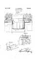
BLANK HOLDER CUSHION Filed Jan. 2, 1948 fnz /nz orr $9} C In 713011 I Patented Jan. 8, 1952 BLANK HOLDER GUSHIGN sl e A 0, 111;, a corpora am tajpes zidgmn eak re ult,
in phe euspion is malm Additional objects, features and advantages of the invention disclosed herein will be apparent to persons skilled in the art after the construction and operation are understood from the withembodying the features of the present invention;
Fig. 2 is a perspective view of an accumulator which may be advantageously adjunctively employed with the blank holder cushion depicted in Fig. 1; and
Fig. 3 is a fragmentary sectionalview of a blank holder cushion means employed as a modification of the blank holder cushion means depicted in Fig. l. e
The drawing is to be understood as being'more or less of a schematic character for the purpose ofillustrating and disclosin a typical or preferred form of the improvements'contemplated herein, and in the drawing like reference characters identify the same parts in the several views.
Referring to the drawing, particularly Fig. 1, wherein the blank holder cushion means with which the invention is particularly concerned and designated in its entirety by the numeral 20, is illustrated as being adjunctively employed, for example, to a conventional double action press designated in its entirety by the letter A and comprising, in general, a punch 21 of any particular shape, adraw'ring 22 complementary L to the punch and adaptable to cooperate with said punch to form, for example, the metal blank B which is advantageously held in position by a hold-down ring 23.
According to the construction of the invention, the metal blank B may be placed between the draw rin 22 and the hold down ring 23, and suitably clamped in this position by an outer ram 24 of the pressA which is adjustable to exert the necessary predetermined pressure to permit the punch 2| to draw the metal blank B without either breaking the bottom or wrinkling the sides thereof. It is notable that too great a pressure will prohibit the proper, fiow of metal and cause breakage or tearing during drawing operations, whereas too little pressure will permit too easy flow of the metal, thereby permitting objectionable wrinkles to form;
"Since the invention is not particularly concerned with the precise construction of theillustrated double action press or its associated parts, they will not be further described in detail, and it is deemed suflicient for all intents and purposes herein contained to show only. portions thereof adjacent to and cooperating with the possible adaptation of the blank holder cushion means as contemplated herein and having described the general environment surrounding said adaptation, the specific construction and cooperating functions of the parts of said blank holder cushion means with which the present invention is particularly concerned, will now be described in detail.
In the exemplary embodiment of the invention depicted in Fig. 1, the blank holder cushion means is shown as being adjunctively employed, for example, to the double action press A, said blank holder cushion means comprising, in general, a blank holder bottom member of any particular shape and being removably secured to the hold-down ring 23 as shown, a
blank holder top member 3| operatively associated with said blank holder bottom member 30 to define a suitable chamber 32 defined by surfaces of the blank holder top member 3| and the blank holder bottom member 30 and adaptable to receive and retain a suitable hydraulic fluid to provide a hydraulic cushion between 7 said blank holder top member and said holder blank holder cushion means contemplated herein.
bottom member, thereby to maintain a constant predetermined equalizing pressure on the blank A which is being held between the hold down ring 23 and the draw ring 22 as shown, whereby equal pressure upon the blank B will be maintained regardless of gauge variations and variations in the thickness and characteristics of the metal stock. An accumulator means designated in its entirety by the numeral (Fig. 2) is operatively connected to said chamber 32, said accumulator means comprising a cylinder and piston arrangement adaptable to maintain a constant hydraulic pressure within the chamber 32. Although I have illustrated one form of accumulator means, it is readily apparent that other forms having the same characteristics may be employed, such as, for example, a constant pressure pump with arelief valve (not shown),
such pumps being sometimes termed as a pressure unloading pump, or any other means may be employed which will allow the selection of a variable constant predetermined pressure.
In accordance with the construction of the present invention the blank holder bottom member 30 is fixedly secured to the hold down ring 23 by means of securing means such as, for example, the bolts having threaded ends adaptable to be received into suitably threaded apertures 46 in the hold down ring 23. Preferably, the blank holder bottom member 30 is a casting having a suitable surface 41 complementary to a related surface 48 of the hold down ring 23. It is notable that suitable recesses have been em- 'ployed between the complementary surfaces 4'! and 48 so that proper alignment between the blank holder bottom member 30 and the hold down ring 23 may be maintained.
Suitable pipe connections as at 50 are employed to operatively connect the chamber 32 with the accumulator means 40 or the pressure unloading pump hereinbefore mentioned, depending on which is employed. These pipe connections may be of any suitable construction pref erably of a flexible type. r f
In orderto prevent'the hydraulic fluid from leaking from the chamber 32, there is provided a suitable packing ring 39 operatively disposed between complementary surfaces of the blank holder top member and the blank holder bottom member and adapted to retain the hydraulic fluid in the chamber 32. ,It can be seen that the seer-see ceive threaded sad 130 pe connecapnea which is *co I M a ted as theaccumulator means; 7 I
draulic systeinherein efere'd provided a passageway -tt in .top member 3| i an in cpeaeemm an I the chamber =32; A suitable valve' means is pre- -titled as at "31- to provide a means-for permitting air in'thesystem to be bledtheretromfi 1 blank holder-top hieinber al may be'made of -la casting rcr edreneahesecretes csmpiame "tai y to top -surraces crane bl'a to! membei flfl. -saom"-F v that the blanklioldez pImlnbel Gt disposed "its operelti-velpositior n a manner sothatit may be moved upward oi'. .downwardly due to the tunctionalreaction oflthe hydraulic flu-id in the chamber 32 It is notable: that the movement or'the blank holder member -3iin-the upward direction 'is restricted as to amount by means of the bolts fit ivhich 'a're providedwi-tha suitable cap =56 adaptable to engage a seat 53, which engagement is adaptable tof-restrict any further upward movement i espect "to the blank holder bottom member 31). Moreovehthe degree or upward movement may be adtusted by reguiation bf the distance the' bol-ts 55 am re ceived. into the suitably threaded apertures- 58 in the blankholde'rbottm member such adjustmnt' be-ing maintained in locked position by means of a uitableiamhnutifl,
In accordance with the construction of the present invention, downward. pressure upon. the blank holder top member 3! isexe'rted by an out.- Side ram .m mbst- 2. in the-deadbea the arrow 60 in Fig. 1.""Since thep ssure exerted by the ac sm-bet- T11 may be seen d posedin the chamber a A iorinly distributedpressure "upon thef'bl [B regardless of gaugevariations variations 'in the thicknessjangla ..haragt,e ristigs of the metal stock. It can be seen th 1; the pressure uponthe blank B'would vary fror' Q ith'e "diiferences' in g g si'iccessive'blanksof metal ck." It is of paramount importance in drawing operations of the type contemplated herein that the pressure be equal with respect to each piece of metal stock employed. Too great a pressure will prohibit the proper flow of metal and cause breakage, whereas too little a pressure will permit too easy a flow of the material and permit wrinkles to form during the drawing operation. Without equalized pressure, excessive scrap and waste in drawing operations would occur because of the nonadjustability of present day double action presses to compensate for such hereinbe'fore described variations in metal stock thicknesses.
Adverting to Fig. 3 wherein a modified structure of the present invention is illustrated, it can be seen that a tube-like member El is operatively disposed in the chamber 32 of the embodiment shown in Fig. 1. In accordance with the construction of the embodiment illustrated in Fig. 3 the blank holder cushion comprises, in general, a blank holder bottom member 62, a blank holder top member 63, a tube-like member 6| made of a flexible material such as, for example, rubber 5 and being adaptable to receive and retain a suit able hydraulic fltiid," saidtu-b'e like member being operatively is osed-teamed s'a-id' blank holder bottom member 3:! and racing adaptable to maintain a constant pressure the blank B which is'be-ingheld between the hold down ring tit-and the draw-ring 22 as shown in Fig. '1, whereby equafpressure upon the blank B will be-maintained regardless of gauge variations in thethiokness and characteristics of the metal stock, and a means, such as a pipe 59 operatively connected to said tube-like member 6| and adaptable to maintain a constant variable hydraulic' pressure within the tube-like member 64.
Adverting to Fig. 2,'wherein there isil lustrated one form adaptable to-maintain a constant variable hydraulic pressure, the accumulator means all? comprises'i-n generala cylinder is having-operatively disposed ther' a piston it operated by a suitable hydraulic time 13-, said piston havinga predetermined number of weights it related thereto by means of a lever-"arrangement it, said cylinder being operatively connectedte the chamber 32 of the tube-like members-i, depending upon which one of the two designs'is employed, by means of suitable flexible tubing as at 58-. Iscan be seen that the lever arrangement will .cause a predetermined-pressure upon the piston which will cause the compression of the hy-- drau-lic flu-id 'il in thecylinder which pressure in turn will be transmitted to the chamber 32 or to the tube-like member at, as the case may-be, by means of the flexible hose 50:, whereby-an equal pressure will be maintained'upon the blank piece B regardless of variations thickness ofthe metal stock. The amount ofpressure desired maybe obtained by the removal or addition of weights 73. Moreover, the device contemplated herein will compensate for. such variations in the thicknessof-the metal stockbycausing variations in the. amount of hydraulic fluid contained in the chamber 32 or the tube-like member M, as the-case may be. It isdmportantto understand that the differential in the thickness of metal stock is transmitted through the chamber 32 or the-tube-likemember 64 which causesjthevariations of the amount of-hydraulic fluid contained within such chamber 3-2 or such tube-like mem ber 61 and such excessive fluid will be caused to flow between said chamber] or; said member and the cylinder 75- of the accumulator 4i]. Equal pressure atall times is maintained by the, provision of the Weighted piston arrangement hereinbefore described and illustrated in the drawing.
While the illustrated accumulator means All may be advantageously employed in the construction of the present invention, it can be seen that other forms may be readily substituted, such as,
,for example, a constant pressure pump with a relief valve, such pump sometimes being termed a pressure unloading pump, or any other means may be advantageously employed which will allow the selection of a constant variable predetermined pressure. It is apparent that such devices, when adjunctively employed to the blank holder cushion arrangement hereinbefore described and with which the present invention is particularly concerned, each will accomplish the same results and are replaceable one by the other.
It is notable that the mechanism disclosed herein may be advantageously employed in mass production manufacturing methods where quick and easy drawing operations result in economies in manufacture which determine the final cost of the units drawn.
From the foregoing disclosure, it may be observed that I have provided a blank holder cushion which efiiciently fulfills the objects thereof as hereinbefore set forth and provides numerous advantages which may be summarized as follows:
1. structurally simple, efficient and durable; 2. Economical to manufacture and readily adaptable to mass production manufacturing principles; and
3. The provision of a blank holder cushion readily adaptable for inporporation in double action presses and providing a constant equalizing predetermined'pressure on the blank positioned therein, regardless of gauge variation of the metal blank.
While I have illustrated a preferred embodiment of my invention, many modifications may be made without departing from the spirit of my invention and I do not wish to be limited to the precise details of construction set forth but wish to avail myself of all changes within the scope of the appended claims.
I claim:
1. A blank drawing press comprising a drawing punch, a drawing die arranged to receive said punch, a hold-down member associated with said die for holding a blank in position, pressure means for urging said hold-down member toward said die, pressure distributing means interposed between said hold-down member and said pressure means comprising a first block disposed about said punch and having a channel formed therein surrounding said punch, a second block disposed about said punch and associated with said first block, a complementary protruding portion of said second block extending into said channel to define therewith an enclosed pressure chamber, a surface of said second block bearing against an opposed surface of said holddown member, said opposed bearing surfaces having complementary recessed and shouldered portions for the purpose of aligning said holddown member and said pressure distributing means, means carried by one of said blocks and connected to the other of said blocks for limiting the movement of said blocks in opposite directions, sealing means interposed between saidprotruding portion and the walls of said channel to prevent leakage from said chamber, a hydraulic fluid in said chamber, and accumulator means connected .to said chamber for supplying and maintaining a predetermined hydraulic pressure in said chamber.
2. A blank drawing press comprising a drawing punch, a drawing die arranged to receive said punch, a hold-down member associated with said die for holding a blank in position, pressure means for urging said hold-down member toward said die, pressure distributing means interposed between said hold-down member and said pressure means comprising a first block disposed about said punch and having a channel formed therein surrounding said punch, a second block disposed about said punch and associated with said first block, a complementary protruding portionof said second block extending into said channel to define therewith an enclosed pressure chamber, a surface of said second block bearing against an opposed surface of said holddown member, said opposed bearing surfaces having complementary recessed and shouldered portions for the purpose of aligning said holddown member and said pressure distributing means, means carried by one of said blocks and connected to the other of said blocks for limiting the movement of said blocks in opposite directions, sealing means interposed between said protruding portion and the walls of said channel to prevent leakage from said chamber, a hydraulic fluid in said chamber, accumulator means connected to said chamber for supplying and maintaining a predetermined hydraulic pressure in said chamber, and a vent passage defining means including a control valve for controlling venting of air trapped in said pressure chamber connected to the side of said pressure chamber.
ROY C. INGERSOLL.
- REFERENCES CITED The following references are of record in the file of this patent:
UNITED STATES PATENTS Number 7 Name Date 349,718 Hollerith Sept. 28, 1886 1,503,131 Nelson July 29, 1924 1,562,953 Glasner Nov. 24, 1925 1,844,250 Hawkins Feb. 9, 1932 1,966,758 Haverbepk July 17, 1934 2,224,956 Ernst Dec, 1'7, 1940 FOREIGN PATENTS Number Country Date 136,634 Germany 1902 652,601 Germany 1937
Priority Applications (1)
| Application Number | Priority Date | Filing Date | Title |
|---|---|---|---|
| US157A US2581663A (en) | 1948-01-02 | 1948-01-02 | Blank holder cushion |
Applications Claiming Priority (1)
| Application Number | Priority Date | Filing Date | Title |
|---|---|---|---|
| US157A US2581663A (en) | 1948-01-02 | 1948-01-02 | Blank holder cushion |
Publications (1)
| Publication Number | Publication Date |
|---|---|
| US2581663A true US2581663A (en) | 1952-01-08 |
Family
ID=21690180
Family Applications (1)
| Application Number | Title | Priority Date | Filing Date |
|---|---|---|---|
| US157A Expired - Lifetime US2581663A (en) | 1948-01-02 | 1948-01-02 | Blank holder cushion |
Country Status (1)
| Country | Link |
|---|---|
| US (1) | US2581663A (en) |
Cited By (4)
| Publication number | Priority date | Publication date | Assignee | Title |
|---|---|---|---|---|
| US2989019A (en) * | 1957-05-20 | 1961-06-20 | Budd Co | Method of deep drawing sheet material |
| DE1247999B (en) * | 1961-04-28 | 1967-08-24 | Metallwaren Und Maschinenfabri | Pulling device with two pressure medium cylinders |
| US3420089A (en) * | 1966-02-16 | 1969-01-07 | Mc Donnell Douglas Corp | Variable pressure drawpress and method |
| US3656335A (en) * | 1970-06-24 | 1972-04-18 | Strolle Corp The | Wall ironing tool pack |
Citations (8)
| Publication number | Priority date | Publication date | Assignee | Title |
|---|---|---|---|---|
| DE136634C (en) * | ||||
| US349718A (en) * | 1886-09-28 | hollerith | ||
| US1503131A (en) * | 1922-01-16 | 1924-07-29 | Marquette Tool & Mfg Co | Power press |
| US1562953A (en) * | 1922-02-18 | 1925-11-24 | Marquette Tool & Mfg Co | Blank holder |
| US1844250A (en) * | 1930-02-01 | 1932-02-09 | Mccord Radiator & Mfg Company | Draw press |
| US1966758A (en) * | 1929-05-10 | 1934-07-17 | Haverbeck Edgar | Sheet-metal press |
| DE652601C (en) * | 1936-05-09 | 1937-11-03 | Heinrich Ewald Kranenberg | Press with pulling device |
| US2224956A (en) * | 1938-05-23 | 1940-12-17 | Hydraulic Dev Corp Inc | Press with rapid-closing upwardacting ram |
-
1948
- 1948-01-02 US US157A patent/US2581663A/en not_active Expired - Lifetime
Patent Citations (8)
| Publication number | Priority date | Publication date | Assignee | Title |
|---|---|---|---|---|
| DE136634C (en) * | ||||
| US349718A (en) * | 1886-09-28 | hollerith | ||
| US1503131A (en) * | 1922-01-16 | 1924-07-29 | Marquette Tool & Mfg Co | Power press |
| US1562953A (en) * | 1922-02-18 | 1925-11-24 | Marquette Tool & Mfg Co | Blank holder |
| US1966758A (en) * | 1929-05-10 | 1934-07-17 | Haverbeck Edgar | Sheet-metal press |
| US1844250A (en) * | 1930-02-01 | 1932-02-09 | Mccord Radiator & Mfg Company | Draw press |
| DE652601C (en) * | 1936-05-09 | 1937-11-03 | Heinrich Ewald Kranenberg | Press with pulling device |
| US2224956A (en) * | 1938-05-23 | 1940-12-17 | Hydraulic Dev Corp Inc | Press with rapid-closing upwardacting ram |
Cited By (4)
| Publication number | Priority date | Publication date | Assignee | Title |
|---|---|---|---|---|
| US2989019A (en) * | 1957-05-20 | 1961-06-20 | Budd Co | Method of deep drawing sheet material |
| DE1247999B (en) * | 1961-04-28 | 1967-08-24 | Metallwaren Und Maschinenfabri | Pulling device with two pressure medium cylinders |
| US3420089A (en) * | 1966-02-16 | 1969-01-07 | Mc Donnell Douglas Corp | Variable pressure drawpress and method |
| US3656335A (en) * | 1970-06-24 | 1972-04-18 | Strolle Corp The | Wall ironing tool pack |
Similar Documents
| Publication | Publication Date | Title |
|---|---|---|
| US2728317A (en) | Apparatus for hydraulic die forming | |
| US2075847A (en) | Art of drawing | |
| US3786667A (en) | Apparatus for and method of making a nestable container | |
| US3724247A (en) | Production of deep drawn pressings | |
| Ahmetoglu et al. | Improvement of part quality in stamping by controlling blank-holder force and pressure | |
| US2783727A (en) | Cushion die structure for apparatus for pressing sheet metal shapes | |
| US2581663A (en) | Blank holder cushion | |
| CN201618774U (en) | Pneumatic die cushion device | |
| US1980882A (en) | Hydraulic pressure device for rolling mills | |
| US2399775A (en) | Means for drawing, forming, shaping, or embossing sheet metal and the like | |
| US1861337A (en) | Hydraulic metal drawing press | |
| US2302953A (en) | Method of metal stretching, using blank-holder types of presses | |
| US1884700A (en) | Drawing press hydraulic cushion | |
| US2796253A (en) | Cushion control system for a press | |
| US5255550A (en) | Device for drawing sheet materials in particular sheet blanks | |
| US3130963A (en) | Internally stabilized deep draw cushion for punch presses | |
| US1844250A (en) | Draw press | |
| US2936055A (en) | Overload protected mechanical press | |
| US2007290A (en) | Power press | |
| US2507194A (en) | Shape-forming device | |
| US4825681A (en) | Pneumatic press counterbalance and cushion construction | |
| US3031993A (en) | Metal-forming press | |
| EP0961683B1 (en) | A device for holding a blank in a fluid cell press and a fluid cell press | |
| US1778358A (en) | Drawing press | |
| US1550626A (en) | Power press |